US4399200A - Device for controlling a pump in a storage battery - Google Patents
Device for controlling a pump in a storage battery Download PDFInfo
- Publication number
- US4399200A US4399200A US06/318,468 US31846881A US4399200A US 4399200 A US4399200 A US 4399200A US 31846881 A US31846881 A US 31846881A US 4399200 A US4399200 A US 4399200A
- Authority
- US
- United States
- Prior art keywords
- voltage
- signal
- level
- motor
- improvement
- Prior art date
- Legal status (The legal status is an assumption and is not a legal conclusion. Google has not performed a legal analysis and makes no representation as to the accuracy of the status listed.)
- Expired - Lifetime
Links
Images


Classifications
-
- H—ELECTRICITY
- H01—ELECTRIC ELEMENTS
- H01M—PROCESSES OR MEANS, e.g. BATTERIES, FOR THE DIRECT CONVERSION OF CHEMICAL ENERGY INTO ELECTRICAL ENERGY
- H01M10/00—Secondary cells; Manufacture thereof
- H01M10/42—Methods or arrangements for servicing or maintenance of secondary cells or secondary half-cells
- H01M10/4214—Arrangements for moving electrodes or electrolyte
-
- H—ELECTRICITY
- H01—ELECTRIC ELEMENTS
- H01M—PROCESSES OR MEANS, e.g. BATTERIES, FOR THE DIRECT CONVERSION OF CHEMICAL ENERGY INTO ELECTRICAL ENERGY
- H01M12/00—Hybrid cells; Manufacture thereof
- H01M12/08—Hybrid cells; Manufacture thereof composed of a half-cell of a fuel-cell type and a half-cell of the secondary-cell type
- H01M12/085—Zinc-halogen cells or batteries
-
- H—ELECTRICITY
- H01—ELECTRIC ELEMENTS
- H01M—PROCESSES OR MEANS, e.g. BATTERIES, FOR THE DIRECT CONVERSION OF CHEMICAL ENERGY INTO ELECTRICAL ENERGY
- H01M10/00—Secondary cells; Manufacture thereof
- H01M10/60—Heating or cooling; Temperature control
- H01M10/61—Types of temperature control
- H01M10/613—Cooling or keeping cold
-
- H—ELECTRICITY
- H01—ELECTRIC ELEMENTS
- H01M—PROCESSES OR MEANS, e.g. BATTERIES, FOR THE DIRECT CONVERSION OF CHEMICAL ENERGY INTO ELECTRICAL ENERGY
- H01M10/00—Secondary cells; Manufacture thereof
- H01M10/60—Heating or cooling; Temperature control
- H01M10/65—Means for temperature control structurally associated with the cells
- H01M10/655—Solid structures for heat exchange or heat conduction
- H01M10/6556—Solid parts with flow channel passages or pipes for heat exchange
-
- H—ELECTRICITY
- H01—ELECTRIC ELEMENTS
- H01M—PROCESSES OR MEANS, e.g. BATTERIES, FOR THE DIRECT CONVERSION OF CHEMICAL ENERGY INTO ELECTRICAL ENERGY
- H01M10/00—Secondary cells; Manufacture thereof
- H01M10/60—Heating or cooling; Temperature control
- H01M10/65—Means for temperature control structurally associated with the cells
- H01M10/656—Means for temperature control structurally associated with the cells characterised by the type of heat-exchange fluid
- H01M10/6567—Liquids
-
- H—ELECTRICITY
- H01—ELECTRIC ELEMENTS
- H01M—PROCESSES OR MEANS, e.g. BATTERIES, FOR THE DIRECT CONVERSION OF CHEMICAL ENERGY INTO ELECTRICAL ENERGY
- H01M50/00—Constructional details or processes of manufacture of the non-active parts of electrochemical cells other than fuel cells, e.g. hybrid cells
- H01M50/70—Arrangements for stirring or circulating the electrolyte
- H01M50/77—Arrangements for stirring or circulating the electrolyte with external circulating path
-
- Y—GENERAL TAGGING OF NEW TECHNOLOGICAL DEVELOPMENTS; GENERAL TAGGING OF CROSS-SECTIONAL TECHNOLOGIES SPANNING OVER SEVERAL SECTIONS OF THE IPC; TECHNICAL SUBJECTS COVERED BY FORMER USPC CROSS-REFERENCE ART COLLECTIONS [XRACs] AND DIGESTS
- Y02—TECHNOLOGIES OR APPLICATIONS FOR MITIGATION OR ADAPTATION AGAINST CLIMATE CHANGE
- Y02E—REDUCTION OF GREENHOUSE GAS [GHG] EMISSIONS, RELATED TO ENERGY GENERATION, TRANSMISSION OR DISTRIBUTION
- Y02E60/00—Enabling technologies; Technologies with a potential or indirect contribution to GHG emissions mitigation
- Y02E60/10—Energy storage using batteries
Definitions
- the present invention relates to the art of controlling electric storage batteries and, more particularly, to an improved pump control device for use in an electric storage battery control system.
- the invention is particularly applicable for controlling the pump or pumps employed in a halogen hydrate type of electric storage battery of the general type disclosed in U.S. Pat. No. 3,935,024.
- This patent is incorporated for reference herein as an example of the type of storage battery employing the pump or pumps and to which the present invention is directed.
- This voltage is applied to the storage battery during a charging operation and it is created by the battery during normal discharge or driving of the vehicle. Consequently, the basic on-board power supply of a motor vehicle of this type has an available main voltage level, which in practice is 120 volts D.C. This allows efficient operation of a drive motor.
- Zinc-chloride and other metal halogen storage batteries require at least one motor driven pump. This pump circulates electrolyte through the cells during both charging and discharging of the battery.
- this type of battery incorporates a second pump usually a gas pump which is used to exhaust halogen, in practice chlorine, from the main battery compartment to a storage compartment wherein the chlorine is formed into a chlorine-hydrate. This action occurs during charging.
- this second pump may be used during discharging to facilitate the flow of chlorine from the hydrate storage area to the main battery compartment. Since these two pumps are to be used both in a discharging mode and a charging mode, they are driven by D.C. motors which normally respond to a voltage level corresponding to the available voltage on the vehicle. Generally this level is the high voltage level of the main storage battery, in practice 120 volts D.C. By providing one or more D.C. motor driven pumps in a battery system for use on a vehicle, it is necessary to provide a control system for these pumps so that they are operated in accordance with the desired parameters existing at any given time in the battery system.
- the pumps must have variable speed which is accurately controlled to optimize the chemical and physical parameters employed in the complex circulatory and chemical systems embodied in a zinc-chloride type of battery. Controlling the pumps is somewhat complex procedure if the pumps are to be a factor in optimizing the operation of the battery. Such optimization is required to obtain uniform operation and long life of a battery for powering a motor vehicle. Control of these pumps is further complicated by the exigencies of the variable conditions under which the main battery must operate. When the pumps are stopped, the cells do not produce maximum voltage; however, the operation of a pump, particularly at this time, is crucial to battery start-up. During such start-up, it is essential that the battery be operated in accordance with the preselected plan to bring the battery into its starting mode.
- the pumps must be operable at a controlled speed at variable voltage levels of the main battery and during periods of time when the main battery has no output voltage, i.e. when the only available on-board electricity comes from an auxiliary storage battery of the 12 volts type.
- the pumps since one critical factor of commercial acceptance in a vehicle is the mileage between charges, the pumps must not be a major consumer of available stored energy. This requires accurate monitoring of adverse conditions when the pump or pumps draw substantial current. Thus, it is necessary that the pumps not be allowed to draw substantial currents for prolonged times without some type of external attention.
- the present invention relates to improved arrangements for controlling pumps of the type used in a storage battery on a motor vehicle and it will be described with particular reference thereto; however, it is appreciated that the invention has broader applications and may be used in other environments.
- a system for controlling the D.C. pumps associated with the main battery used in driving a motor vehicle which system provides accurate control of the pumps over variable voltage conditions and also prevents the pumps from drawing substantial current for prolonged periods without operator attention.
- This type of system includes a circuit for applying an average voltage to the motor and means for generating a reference signal for controlling the general magnitude of the average applied voltage to drive the pump at the desired speed.
- the improvement in this type of a system is the provision of means for supplying a main voltage level of a given magnitude, means for alternately switching the main voltage level across the motor wherein the switching means has a first condition with a voltage level applied across the motor and a second condition with the voltage level isolated from the motor and signal generating means normally responsive to a voltage control signal controlled at least in part by the reference signal for creating a signal to change the relative time the switching means is in the first condition compared to the time the switching means is in the second condition.
- the pump is driven in accordance with the reference signal at a desired speed.
- the reference signal is modified in accordance with the feedback signal from the voltage applied to the pump to further control the operation of the pump.
- the current used by the D.C. motor driving the pump is sensed and current controlled signal is created. This signal is used to control the pump when the current control signal exceeds a preselected value. In this manner, the motor driving the pump can be shifted from normal operation when the motor voltage is monitored to control speed to another operation wherein the current used by the motor is used to control motor speed. This last condition is sensed by the operator or an on-board microprocessing system to assure that the pump motors and the battery are given attention to prevent long term limiting operation.
- a system as defined above which system includes a power supply for creating the main supply of voltage used for driving the pump motors.
- the system includes means for providing an electrical system with a fixed D.C. voltage level by an auxiliary battery separate from the main storage battery, means for providing a second D.C. voltage level by the main storage battery itself and variable between a lower voltage level and a higher generally fixed operating voltage level and means for creating the main voltage level for the pump motors by the first voltage level until the second voltage level exceeds a given value.
- the pumps are driven by the auxiliary battery on the vehicle when the main zinc-chloride type of battery does not have sufficient voltage to drive the pump motors. Consequently, during start-up, the pump control system is operated by the auxiliary storage battery which can be standard lead-acid battery.
- the primary object of the present invention is the provision of an improved system for controlling the operating pumps of a storage battery, which improvement allows accurate control of the pump operation during variations in the conditions experienced by the pump motor in the operation of the main battery.
- Yet another object of the present invention is the provision of an improved system as defined above, which improved system normally controls the speed of the motors driving the pumps by alternately switching on and off a voltage level corresponding to the output level of the main battery at a controlled rate. This provides duty cycling of the D.C. motors driving the pumps so that it is not necessary to vary the magnitude of the voltage applied to the pump motors.
- Still a further object of the present invention is the provision of an improved system as defined above, which system allows operation of the motors driving the pumps by a wide variation in the control level supplied to the pump so that the control system can operate during varying conditions existing in the storage battery.
- Another object of the present invention is the provision of an improvement as defined above, which improvement allows the pumps to be driven selectively by the auxiliary storage battery on a vehicle, at least during cold start-up when the output voltage of the main battery is below a preselected level.
- Still a further object of the present invention is the provision of a pump control system which can be operated at a current control system to match the exigencies existing in the operation of a storage battery requiring control of such parameters as pressure and temperature to optimize its operation.
- Still a further object of the present invention is the provision of an improved system for controlling the pump motors of the type employed in a storage battery, which pump motors consume a minimum amount of electrical energy, thus do not substantially decrease the mileage between charging cycles of a main storage battery.
- FIG. 1 is a side view of a motor vehicle employing a zinc-chloride type of battery to which the present invention is particularly directed;
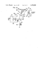
- FIG. 2 is a schematic, pictorial view showing the battery as employed in the vehicle of FIG. 1 together with the arrangement of the pumps controlled in accordance with the present invention
- FIG. 3 is a schematic, cross-sectional view and flow chart showing a battery employing pumps of the type to which the present invention is directed and operating in the charging mode;
- FIG. 4 is a cross-sectional view and flow chart, similar to FIG. 3, showing the battery being operated in the discharge or normal mode;
- FIG. 5 is a block diagram showing the overall system for controlling two pumps by the preferred embodiment of the present invention.
- FIG. 6 is a combined block and wiring diagram showing a power supply constructed in accordance with one aspect of the present invention.
- FIG. 7 is a block and wiring diagram showing a simplified view of a control system constructed in accordance with the present invention and shown generally in the system of FIG. 5;
- FIG. 7A is a chart showing an operating characteristic of a preferred embodiment of the present invention.
- FIG. 7B is a wiring and block diagram similar to FIG. 7 showing certain details of one aspect of the present invention.
- FIG. 8 is a graph illustrating the operating characteristic of the duty cycle oscillator employed in the preferred embodiment of the present invention.
- FIG. 9 is a chart showing output signals employed in the duty cycle oscillator of the preferred embodiment of the present invention.
- FIGS. 10A, 10B, 10C, 10D and 10E are to be taken together and are the wiring diagram now used to practice the present invention.
- FIG. 11 is a flow diagram showing certain operating characteristics of a system employing the present invention.
- FIGS. 1-4 show an electric powered motor vehicle A driven by storage battery B of the zinc-chloride type, generally shown in U.S. Pat. No. 3,935,024, incorporated by reference herein.
- This type of battery is manufactured by/or for Energy Development Associates and has a substantially greater driving range between charges than other batteries being suggested for use in electric powered motor vehicles.
- This zinc-chloride battery is now being considered as a power source for electric powered motor vehicles such as vehicle A.
- a zinc-chloride battery or similar battery includes a stack portion 10 containing the electric cells and a reservoir or sump 12 for storage of electrolyte.
- Piping 14, including return lines 14a, 14b and pressure line 14c, is employed for circulating electrolyte by circulation pump 20, driven by motor 22 and designated P1.
- Storage tank 30 for chlorine-hydrate is connected by an appropriate gas line, not shown, includes an internal pump 32 for moving gaseous material, i.e. chlorine, between stack 10 and tank 30 during charging and discharging of battery B.
- Pump 32 is driven by motor 34 designated P2.
- battery B of vehicle A is a standard zinc-chloride battery having, in the preferred embodiment, two groups of thirty cells, each of which produces approximately 2.0 volts D.C.
- the output across battery leads a,b, in practice is approximately 120 volts D.C.
- various voltages could be obtained by different numbers of battery cells in stack 10.
- This type of storage battery is charged in accordance with the arrangement schematically illustrated in FIG. 3, wherein a zinc-chloride battery is selectively connected to an external power source supply of 120 volts D.C. across terminals a,b.
- pumps 20, 32 are driven by D.C. motors 22, 34, respectively.
- This circulates electrolyte through stack 10 and pumps chlorine, by gas pump 32, into the storage tank 30.
- Chlorine-hydrate is formed in tank 30 due to the chilling action of bypassed electrolyte, which is cooled by an external coolant circulated through lines 80, 82.
- Electrolyte is drawn into pump 32 through line 84 which is illustrated as being undulating to facilitate cooling of the chlorine passing through adjacent line 86 and into pump 32.
- lines 84 and 86 could be combined prior to reaching the inlet of pump 32.
- Solenoid 90 is actuated to bleed or bypass a small amount of electrolyte through line 84 for chlorine-hydrate formation at pump 32.
- This chlorine hydrate is stored in tank 30 for use during the discharge or normal operating mode of battery B, as shown in FIG. 4.
- the amount of electrolyte circulating through line 84 is controlled by a valve shown schematically as solenoid 90.
- pump 20 is driven by motor 22 to circulate electrolyte through stack or battery compartment 10. This creates a voltage across leads or lines a,b.
- FIGS. 3 and 4 are representative of a system using a zinc-chloride battery of the type to which the present invention is directed. These types of batteries employ two or more pumps, in the illustration, pumps 20, 32. Of course, various modifications could be made in the basic parameter for operation of the battery B. For instance, pump 32 is operated during discharge to heat the chlorine-hydrate in tank 30 for the purpose of liberating chlorine. This is done by bleeding warm electrolyte from compartment 10 through line 84. The pumps shown in FIGS.
- FIG. 5 a system employing the preferred embodiment of the present invention to control pumps of a storage battery is illustrated as a system for controlling pumps 20, 32 through motors 22, 34, respectively, as discussed with respect to the illustrative embodiment of FIGS. 1-4.
- an appropriate on-board microprocessor 100 receives an executive program from PROM 102 to control the complete operation of battery B.
- PROM 102 receives an executive program from PROM 102 to control the complete operation of battery B.
- This type of system also employs a RAM 104 for temporary storage of binary information used in processing the executive program of PROM 102.
- an appropriate MAP or MAPs 106 are used so that characteristics either on the real time basis for otherwise can be compared with information permanently stored in the MAPs to determine the operating characteristics of battery B at any given time.
- Time may be related to charge condition and not real time.
- the MAPs or other storage arrangement can store the desired speed of pumps 20, 32 at any given time or under any given circumstances, such as pressure, temperature, charged state.
- the information is sought from a storage area, represented as MAPs 106, and is outputted by microprocessor 100 on appropriate data bus 110.
- the executive program continues monitoring parameters in battery B and updates, periodically, the desired speed of the pumps at any given time.
- This type of control arrangement is general in nature and is shown in the preferred embodiment as the desired system for outputting information regarding the desired operation of pumps 20, 32 or any other pumps involved in the operation of battery B.
- the particular arrangement or control system for obtaining information regarding the desired speed of pumps 20, 32 does not form a part of the invention and is illustrated only for completeness of disclosure.
- the pump control PC is constructed in accordance with the preferred embodiment of the present invention and is employed with each pump 20, 32 to be controlled.
- two pumps 20, 32 are to be controlled; therefore, two pump control circuits or devices PC are employed. These controls are identical; therefore, only the pump control PC used to control the voltage applied to motor 22 will be described in detail. This description applies equally to the pump control used to apply voltage across motor 34.
- a single power supply PS is used to control the voltage levels applied to each of the pump controls PC. This power supply forms one aspect of the present invention and is shown in detail in FIGS. 6 and 10D. For the purpose of a general explanation, as shown in FIG.
- power supply PS includes a command line 120 which receives binary logic from data bus 110, which logic may be latched in an appropriate latch L, such as a flip-flop. As long as a preselected logic is applied to line 120, power supply PS is operated to produce voltage to pump controls PC.
- the positive output voltage of battery B is applied to power supply PS at line 122.
- An external 12 volts D.C. is also applied to power supply PS through line 124 connected to the auxiliary lead-acid battery also mounted on vehicle A.
- the main voltage output of power supply PS is applied to line 130. This voltage output varies in accordance with the graph shown in FIG. 7A and is ultimately the voltage level of battery B. Power supply PS also creates an internal 12 volts voltage in line 132.
- the output of power supply PS is essentially an internal 12 volts supply (12 V INT), on line 132 and a main voltage on line 130. Both of these voltage levels are directed to the input of pump control PC.
- power supply PS monitors the voltage of battery B and produces a monitoring signal in lines 174. These lines are directed to data bus 110 for use by microprocessor 100.
- latch L is reset and the command logic in line 120 is removed to transfer control of the input voltage to pump controls PC from the auxiliary or external voltage supply of line 124 through the main power bus of battery B attached to line 122.
- voltage in lines 140, 142 is applied across motors 22 in accordance with the operation of pump control PC.
- the positive voltage level feedback in line 150 (V F1 + ) is directed from line 140 back to pump control PC.
- the applied voltage is monitored at line 152 which is a feedback (V F1 - ) connected between negative power line 142 and pump control PC.
- the general voltage level applied to motor 22 is read by line 150 and the average applied voltage is read by line 152.
- the reference signal in 160 provides a current which is at a level to set the desired speed of pump motor 22.
- This information is provided to pump control PC by microprocessor 100 in accordance with standard control practice.
- motors which are controlled by the average applied voltage could be used for motors 22, 34, in practice Model 1 No. MC19P motor by CEM of Dyon, Cedex, France is used. These motors have a rating of 1.0 KW at 3000 RPM with 83.0 average voltage and 14.4 amperes. At 1.6 KW a speed of 3000 RPM is obtained with 85.5 volts and 22.2 amperes. (See U.S. Pat. Nos. 3,090,880 and 3,144,574).
- pump control PC is provided with an arrangement for converting the control of motor 22 from a voltage control to a current limiting control.
- logic on the current limiting (CL) line 170 is directed from pump control PC to the data bus 110.
- information in line 172 indicates that pump control PC has energized motor 22 in accordance with a command received from data bus 110.
- FIG. 10D receives a binary command signal in line 120 as previously mentioned. This command signal is created when an operator closes a switch to start vehicle A. Also, the vehicle must be in a discharge mode and not connected to an external charging unit.
- Microprocessor 100 receives information from lines 174 that battery B has a certain voltage level. In practice if the voltage exceeds approximately 75 volts, there is no command given to switch 200. This voltage level will be realized when vehicle A has been recently driven.
- switch 200 Assuming that there is a start request with a cold battery, then a command signal is received by switch 200. This energizes converter 202 for converting 12 volts from the auxiliary battery in line 124 to 24 volts in line 204. Diode 206 connects line 204 with main voltage supply line 130. Thus, when switch 200 is actuated, 24 volts is directed to line 130. A Zener diode 210 is connected in parallel with a filter capacitor 212 and connected to line 204 by resistor 214. The internal 12 volts of D.C. power (12 volts INT) previously described is maintained at line 132.
- This power level is maintained by converter 202 until the voltage in line 122 reaches a level exceeding a level of 24 volts D.C. of output of diode 220. At this time, the voltage in line 122 is balanced by the voltage in line 204 at discriminating point 230 which is also in line 130. As the voltage in line 122 increases, the voltage at the anode of diode 220 exceeds the voltage at the anode of diode 206. When this occurs, the battery voltage in line 122 is applied to resistor 232 for holding the 12 volts condition of line 132 (12 volts INT). Thus, as shown in FIG. 7A, the voltage in line 130 is 24 volts until the B+ voltage exceeds this voltage level.
- the power supply PS includes a voltage divider having resistors 240, 242, 244 and 246 with a center tapped ground 250.
- the voltage across resistor 242 is a positive voltage
- the voltage across resistor 244 is a negative voltage.
- Any information detected by lines 174 is directed to data bus 110 for use in accordance with the executive program.
- the main voltage applied across motor 22 fluctuates in accordance with the graph in FIG. 7A, at least during cold starting of vehicle A.
- Pump control PC is constructed to produce feedback signals for detecting the voltage levels and controlled by the duty cycle of motor 22.
- the average voltage applied to the pump will be controlled by the duty cycle of the voltage across lines 140, 142 in accordance with the desired speed of the pump as directed to the reference line 160.
- the voltage across lines 140, 142 is rapidly applied and removed from motor 22.
- the time of application to the time of removal is the duty cycle.
- the main voltage in line 130 is alternately connected across and isolated from pump motor 22 by a signal generating means in the form of a duty cycle oscillator 300 having a voltage control signal input line 302 and an output line 304, which output line has a first state connecting the main voltage in lines 130 and 140 across motor 22 and a second state isolating this voltage from the motor.
- a signal generating means in the form of a duty cycle oscillator 300 having a voltage control signal input line 302 and an output line 304, which output line has a first state connecting the main voltage in lines 130 and 140 across motor 22 and a second state isolating this voltage from the motor.
- the relative time during which the signal in line 304 is in the first state compared to the time that the signal is in the second state controls the average voltage across motor 22.
- This ratio together with the magnitude of the main voltage in line 130 from power supply PS controls the average voltage across motor 22 and thus controls the speed of the motor in accordance with standard practice.
- FIG. 10B shows an oscillator wherein amplifier 306 is connected to provide oscillations as shown in FIGS. 8 and 9.
- the frequency in line 304 increases to approximately 5.0 KHz and then decreases as shown in FIG. 8 as the duty cycle increases to hundred percent (100%).
- the frequency is approximately 2.0 KHz in line 304.
- the main voltage is connected across motor 22 10% of the time.
- the pulses in line 304 are of a period indicated at x.
- the output of line 304 is oscillating at approximately 5 KHz and the first condition of line 304 is in existence for approximately the same time as the second condition. This produces a period indicated as y.
- the period again increases to a value similar to x. Consequently, voltage controlled oscillator 300 does not have a fixed period to control the duty cycle. In this manner, there is a reduced ripple effect during control of the motor 22 by alternately applying and removing the main voltage from the power supply PS at line 130. By using high frequency, the motor does not experience a pulsating input.
- This oscillator includes operational amplifier 306 biased by the normal 12.0 volt power supply at line 132.
- the output signal in line 304 of oscillator 300 is passed through a buffer 310 to shape the pulses in line 312, which pulses are produced in accordance with the chart shown in FIG. 9.
- These pulses are directed to a switch 320 which is alternately actuated by the signal in line 312.
- switch 320 When switch 320 is in one condition, a voltage, determined by the voltage on line 130, is applied across pump motor 22. The opposite condition of switch 320 disconnects this voltage from across the motor.
- the duty cycle output in line 304 controls the average voltage applied across the pump driving motor. This controls the speed of the motor and, thus, the speed of the pump.
- a diode 322 is connected across lines 140, 142 parallel with a filter capacitor 324.
- switch 320 removes voltage from the pump motor, current flows through diode 322. This current flow is controlled by the impedance of choke or inductor 326.
- Line 330 provides the ground for switch 320 through resistor 332.
- a voltage driven comparitor 340 in the form of an operational amplifier schematically illustrated in FIG. 7.
- This amplifier includes a non-inverted input 342 which is controlled by the reference voltage related to the desired speed of the pump as provided by the control system onto data bus 110, as shown in FIG. 5.
- the inverting input of comparitor 340 is connected to a biasing line 344, which is illustrated as being connected to a feedback (V F ) connected to line 130.
- V F feedback
- This voltage generally relates to the voltage pattern shown in FIG. 7A. Voltage levels in lines 342 and 344 control the voltage in output line 350 of comparitor 340. This voltage is, under normal conditions, the voltage control signal of duty cycle ocillator 300.
- the voltage in line 350 normally controls oscillator 300; however, a discriminating means 360 is interposed between line 350 and line 302 so that when a current limiting situation exists in motor 22, discriminating means 360 shifts the control of oscillator 300 from line 350 to a current limiting input line 416, which is controlled by a current sensing circuit 400, best shown in FIG. 10B.
- This sensing circuit includes an input 402 connected above resistor 332 to detect the general level of current flow in motor 22.
- a detector circuit 404 as best shown in FIG. 10B, is used to indicate when motor 22 is shifted to the ON condition, as indicated by the logic on line 72.
- To control the voltage on line 416 there is provided a comparitor 410, best shown in FIG.
- discriminating means or circuit 360 transfers operation of the oscillator to a current limiting operation wherein the duty cycle is controlled by the voltage in line 416.
- Higher current levels at motor 22 create lower voltages in line 416. This reduces the duty cycle and reduces the current in motor 22. Consequently, the duty cycle of the voltage applied across the motor is controlled by the magnitude of the sensed current.
- An appropriate detector 420 is employed for creating a signal in line 170 that is directed to the microprocessor when a current limiting condition exists. By using discriminating circuit 360, the lowest demand is always employed to control the voltage in line 302. If the demand by the current condition in motor 22 produces a higher voltage in line 416, line 350 controls the voltage in line 302.
- a lower demand signal in line 416 is caused by a high current in the motor.
- line 302 is controlled by the voltage in line 416.
- line 416 controls transistor 422 and line 350 controls transistor 424.
- These two transistors are connected to a common summing point 426 and form the discriminating means 360 of FIG. 7.
- the transistor 422 conducts and point 426 is pulled electrically negative.
- transistor 422 conducts. This pulls point 426 electrically negative.
- the higher conducting of the two transistors 422, 424 controls oscillator 300 by input line 302 in accordance with the scheme discussed in connection with FIGS. 8 and 9.
- comparitor 340 operation of comparitor 340 during normal conditions is illustrated. Under these conditions, oscillator 300 is controlled by comparitor 340 which has a feedback line 152. The level of voltage in this feedback line is indicative of the actual average voltage being applied to pump motor 22.
- This structure is shown in more detail in the upper portion of FIG. 10A and includes means for controlling current in line 440 in accordance with the desired duty cycle or speed of motor 22. As shown in FIG. 10A, this current is controlled by the conductivity of transistor 442 which, in turn, is controlled by the current flow in line 160 as detected by optical coupler 444.
- Rheostat 450 is used to set the maximum voltage when duty cycle is to be 100%.
- Summing point 452 is connected to the input 342 of comparitor 340 and is connected to the negative bus of battery B through capacitor 454 and resistor 456 for the purpose of filtering and adjusting the relationship of current flow at point 452.
- Summing point 452 is also connected with feedback line 152 which is generally responsive to the actual average voltage being applied by oscillator 300 to motor 22. Thus, the relationship at summing point 452 compares the desired and actual operation of motor 22 in normal situations.
- comparitor 340 The other input of comparitor 340 is line 344 connected either to the internal 12.0 volts line 132 or to the positive feedback line 150 which generally follows the profile illustrated in FIG. 7A. Thus, under normal circumstances, line 344 is controlled by the positive bus of battery B.
- circuit 460 is controlled by the positive battery bus as detected by line 150.
- Resistor 470 controls the gain of comparitor 340 and capacitor 472 is a filter capacitor.
- the voltage across the pump motor is the product of the duty cycle and the voltage of the positive bus which is applied at line 130. Since the positive bus is generally fixed at line 140, the voltage at line 142 varies according to the duty cycle. This is sensed by feedback line 152, which modifies the reference signal in line 342 as discussed with respect to FIG. 7. This normal operation can be discontinued when adverse conditions cause high current flow in motor 22.
- FIGS. 10A, 10B, 10C, 10D and 10E are circuits used in practicing the invention as so far described.
- the components employed are labeled and numbers used in the previous description are contained on the elements as found in these drawings.
- the wiring diagram is self-explanatory; however, certain aspects of the actual circuitry used will be discussed as it applies to the preferred embodiment of the present invention, shown in FIGS. 5-9.
- the upper portion relates to the comparitor 340 and its supporting components.
- Optical coupling 444 controls the conductivity of transistor 442 to control the voltage at point 452 as selected by microprocessor 100.
- the feedback signal in line 152 reads the actual average voltage being applied by oscillator 300 to motor 22.
- Point 452 controls noninverting input 342.
- Inverting input at line 344 is controlled either by the feedback in line 150 or the voltage in line 132. These voltages are summed at point 460 and weighted by the values of current flow through resistors 500, 502.
- Comparitor 340 controls detecting transistor 424, as previously described.
- oscillator 300 is controlled by operational amplifier 306 and has the parameters indicated to produce the desired oscillation in line 304, which have been discussed with respect to FIGS. 8 and 9.
- Buffer 310 is a somewhat standard pulse forming circuit to produce binary conditions in line 312 which are to control the average voltage applied across motor 22.
- the lower portion of FIG. 10B illustrates the circuit for the current sensing concept which will be described later.
- the switch 320 includes an enhancement mode MOSFET switch 550 to switch point 552 in accordance with the voltage in line 312. When switch 550 is off, the voltage flows through choke 326. This is sensed by transistor 554 and is available as a voltage across resistor 332.
- This voltage is sensed by line 402 and is directed back to the circuitry shown in FIG. 10B as one input to operational amplifier 560.
- the gain of this amplifier is controlled by resistor 562 so that the amplifier produces a signal in line 530 which is proportional to the actual motor current.
- transistor 570 is switched ON to cause current flow through optical coupler 572. This indicates that motor 22 is operating.
- This logic is sensed by data bus 110 so that such information can be stored in RAM 104.
- the voltage in line 530 is directed to comparitor 410, as shown in FIG. 10A.
- FIG. 10D power supply PS is shown in more detail.
- a command is received in line 120. This causes conduction of transistor 580.
- Current flow in relay coil 582 closes switches 582a, 582b.
- This supplies the external voltage in line 124 from an auxiliary battery to a voltage divider including resistors 590, 592.
- This D.C. voltage is applied to a standard DC-to-DC converter 202 for the purpose of producing a 24.0 volts D.C. voltage in line 204.
- FIG. 10D there is also illustrated, somewhat schematically, a terminal strip 600 which is used in the preferred embodiment to produce output communication with the data bus 110.
- FIG. 10E the pump control for the second motor is schematically illustrated. As can be seen, it duplicates the pump control for motor 22. Each pump used in the storage battery is controlled by a separate control circuit PC. The standard power supply PS can be used for driving each of the several pump controls.
- microprocessor 100 determines whether or not battery B is in the discharge mode. If so, microprocessor 100 determines whether or not the positive bus of battery B is less than about 75.0 volts. If so, power supply PS receives a command in line 120. Microprocessor 100 then monitors the data on lines 174 to read the voltage across the battery. When this voltage exceeds a certain value, illustrated as K volts, a signal is created to remove the binary logic in line 120. This turns off power supply PS. During the initial operation, when power supply PS is energized, the duty cycle is set to 100% by controlling the flow of current through line 160.
- a duty cycle sub-routine is processed by the microprocessor to monitor pump speed and other parameters, such as battery temperature and battery pressure, to produce a new duty cycle which relates to the desired speed of the pump.
- This speed changes from time to time according to sensed parameters, indicated in FIG. 11 as speed.
- These parameters are controlled by fixed patterns stored in MAPs 106 in accordance with standard control practice. This information is used to create a reference voltage for comparitor 340 through current supplied to line 160. During monitoring, the reference is updated as indicated by the flow chart in FIG. 11. This is controlled by the sub-routine for the duty cycle.
- This type of control logic can be modified to produce different desired conditions for the pump in accordance with changing parameters or time during the use of battery B for driving the vehicle A. The lower portion of FIG.
- 11 relates to the concept that when the pump control is in the current limit mode this fact is directed to the microprocessor and stored in the RAM. When this happens, a sub-routine is processed to indicate difficulty, if the battery is not being charged. Indeed, after producing an alarm or light indication, the sub-routine could take other corrective actions.
- the fact that each of the pumps is energized and operated is also stored in RAM.
- pump control PC receives a desired operating information and performs its function to control motors 22, 34 based upon this information.
- the pump control is by voltage sensing and modulation.
- current limiting is available so that the current used by each of the pumps can be limited to prevent substantive reduction in the driving time due to adverse pump loading conditions or other parameters.
Abstract
Description
Claims (28)
Priority Applications (1)
| Application Number | Priority Date | Filing Date | Title |
|---|---|---|---|
| US06/318,468 US4399200A (en) | 1981-11-05 | 1981-11-05 | Device for controlling a pump in a storage battery |
Applications Claiming Priority (1)
| Application Number | Priority Date | Filing Date | Title |
|---|---|---|---|
| US06/318,468 US4399200A (en) | 1981-11-05 | 1981-11-05 | Device for controlling a pump in a storage battery |
Publications (1)
| Publication Number | Publication Date |
|---|---|
| US4399200A true US4399200A (en) | 1983-08-16 |
Family
ID=23238309
Family Applications (1)
| Application Number | Title | Priority Date | Filing Date |
|---|---|---|---|
| US06/318,468 Expired - Lifetime US4399200A (en) | 1981-11-05 | 1981-11-05 | Device for controlling a pump in a storage battery |
Country Status (1)
| Country | Link |
|---|---|
| US (1) | US4399200A (en) |
Cited By (13)
| Publication number | Priority date | Publication date | Assignee | Title |
|---|---|---|---|---|
| US5453334A (en) * | 1995-01-06 | 1995-09-26 | Ford Motor Company | Automatic battery watering system |
| US5606239A (en) * | 1993-09-09 | 1997-02-25 | Bayerische Motoren Werke Ag | Cooling device for electric vehicle battery charger and wiring converter |
| US5672051A (en) * | 1995-07-12 | 1997-09-30 | Walbro Corporation | Power-managed fuel delivery system |
| US5702842A (en) * | 1992-12-23 | 1997-12-30 | Elin Energieanwendung Gesellschaft M.B.H. | Process for charging and discharging zinc/bromine batteries |
| US5704766A (en) * | 1992-09-25 | 1998-01-06 | Itt Automotive Europe Gmbh | Method and circuit arrangement for controlling the flow rate of a hydraulic pump |
| US6322913B2 (en) | 1997-09-24 | 2001-11-27 | Aer Energy Resources, Inc. | Air manager control using cell load characteristics as auto-reference |
| US6824915B1 (en) | 2000-06-12 | 2004-11-30 | The Gillette Company | Air managing systems and methods for gas depolarized power supplies utilizing a diaphragm |
| US20050084745A1 (en) * | 2003-07-09 | 2005-04-21 | Colello Gary M. | Systems and methods for selective cell and/or stack control in a flowing electrolyte battery |
| US20120268048A1 (en) * | 2009-07-22 | 2012-10-25 | Claudio Eduardo Soares | Control system for electric motor applied to cyclic loads and control method for electric motor applied to cyclic loads |
| US8785023B2 (en) | 2008-07-07 | 2014-07-22 | Enervault Corparation | Cascade redox flow battery systems |
| US8906529B2 (en) | 2008-07-07 | 2014-12-09 | Enervault Corporation | Redox flow battery system for distributed energy storage |
| US8916281B2 (en) | 2011-03-29 | 2014-12-23 | Enervault Corporation | Rebalancing electrolytes in redox flow battery systems |
| US8980484B2 (en) | 2011-03-29 | 2015-03-17 | Enervault Corporation | Monitoring electrolyte concentrations in redox flow battery systems |
Citations (6)
| Publication number | Priority date | Publication date | Assignee | Title |
|---|---|---|---|---|
| US3850695A (en) * | 1972-02-05 | 1974-11-26 | Bosch Gmbh Robert | Voltage regulator system for use with fuel cell battery |
| US3935024A (en) * | 1970-06-26 | 1976-01-27 | Energy Development Associates | Halogen hydrates |
| US3996064A (en) * | 1975-08-22 | 1976-12-07 | The United States Of America As Represented By The Administrator Of The National Aeronautics And Space Administration | Electrically rechargeable REDOX flow cell |
| US4098959A (en) * | 1976-12-27 | 1978-07-04 | United Technologies Corporation | Fuel cell fuel control system |
| US4287267A (en) * | 1980-05-27 | 1981-09-01 | Energy Development Associates, Inc. | Zinc-chlorine battery plant system and method |
| US4304823A (en) * | 1980-03-05 | 1981-12-08 | Lemelson Jerome H | Electrical energy storage system |
-
1981
- 1981-11-05 US US06/318,468 patent/US4399200A/en not_active Expired - Lifetime
Patent Citations (6)
| Publication number | Priority date | Publication date | Assignee | Title |
|---|---|---|---|---|
| US3935024A (en) * | 1970-06-26 | 1976-01-27 | Energy Development Associates | Halogen hydrates |
| US3850695A (en) * | 1972-02-05 | 1974-11-26 | Bosch Gmbh Robert | Voltage regulator system for use with fuel cell battery |
| US3996064A (en) * | 1975-08-22 | 1976-12-07 | The United States Of America As Represented By The Administrator Of The National Aeronautics And Space Administration | Electrically rechargeable REDOX flow cell |
| US4098959A (en) * | 1976-12-27 | 1978-07-04 | United Technologies Corporation | Fuel cell fuel control system |
| US4304823A (en) * | 1980-03-05 | 1981-12-08 | Lemelson Jerome H | Electrical energy storage system |
| US4287267A (en) * | 1980-05-27 | 1981-09-01 | Energy Development Associates, Inc. | Zinc-chlorine battery plant system and method |
Cited By (18)
| Publication number | Priority date | Publication date | Assignee | Title |
|---|---|---|---|---|
| US5704766A (en) * | 1992-09-25 | 1998-01-06 | Itt Automotive Europe Gmbh | Method and circuit arrangement for controlling the flow rate of a hydraulic pump |
| US5702842A (en) * | 1992-12-23 | 1997-12-30 | Elin Energieanwendung Gesellschaft M.B.H. | Process for charging and discharging zinc/bromine batteries |
| US5606239A (en) * | 1993-09-09 | 1997-02-25 | Bayerische Motoren Werke Ag | Cooling device for electric vehicle battery charger and wiring converter |
| US5453334A (en) * | 1995-01-06 | 1995-09-26 | Ford Motor Company | Automatic battery watering system |
| US5672051A (en) * | 1995-07-12 | 1997-09-30 | Walbro Corporation | Power-managed fuel delivery system |
| US6322913B2 (en) | 1997-09-24 | 2001-11-27 | Aer Energy Resources, Inc. | Air manager control using cell load characteristics as auto-reference |
| US6824915B1 (en) | 2000-06-12 | 2004-11-30 | The Gillette Company | Air managing systems and methods for gas depolarized power supplies utilizing a diaphragm |
| US20100188045A1 (en) * | 2003-07-09 | 2010-07-29 | Colello Gary M | Systems And Methods For Selective Cell And/Or Stack Control In A Flowing Electrolyte Battery |
| US20050084745A1 (en) * | 2003-07-09 | 2005-04-21 | Colello Gary M. | Systems and methods for selective cell and/or stack control in a flowing electrolyte battery |
| US7939190B2 (en) | 2003-07-09 | 2011-05-10 | Premium Power Corporation | Systems and methods for selective cell and/or stack control in a flowing electrolyte battery |
| US8697267B2 (en) | 2003-07-09 | 2014-04-15 | Premium Power Corporation | Systems and methods for selective cell and/or stack control in a flowing electrolyte battery |
| US9325021B2 (en) | 2003-07-09 | 2016-04-26 | Vionx Energy Corporation | Systems and methods for selective cell and/or stack control in a flowing electrolyte battery |
| US8785023B2 (en) | 2008-07-07 | 2014-07-22 | Enervault Corparation | Cascade redox flow battery systems |
| US8906529B2 (en) | 2008-07-07 | 2014-12-09 | Enervault Corporation | Redox flow battery system for distributed energy storage |
| US20120268048A1 (en) * | 2009-07-22 | 2012-10-25 | Claudio Eduardo Soares | Control system for electric motor applied to cyclic loads and control method for electric motor applied to cyclic loads |
| US8643320B2 (en) * | 2009-07-22 | 2014-02-04 | Whirlpool S.A. | Control system for electric motor applied to cyclic loads and control method for electric motor applied to cyclic loads |
| US8916281B2 (en) | 2011-03-29 | 2014-12-23 | Enervault Corporation | Rebalancing electrolytes in redox flow battery systems |
| US8980484B2 (en) | 2011-03-29 | 2015-03-17 | Enervault Corporation | Monitoring electrolyte concentrations in redox flow battery systems |
Similar Documents
| Publication | Publication Date | Title |
|---|---|---|
| US4399200A (en) | Device for controlling a pump in a storage battery | |
| US5635771A (en) | Secondary accumulator charging/discharging for a motor vehicle using a controllable resistor | |
| US6784635B2 (en) | Vehicle electrical system | |
| US7477038B2 (en) | Vehicle-mounted power supply system | |
| US4308492A (en) | Method of charging a vehicle battery | |
| US8863540B2 (en) | HVAC system controlled by a battery management system | |
| US7196492B2 (en) | Power supply apparatus including fuel cell and capacitor, and operation method thereof | |
| US4309644A (en) | Electric vehicle controller adapted for charge station connection | |
| US5952813A (en) | Battery charging system and electric vehicle with battery charging system | |
| US6745117B1 (en) | Power-limiting control method and system for a work vehicle | |
| US5659240A (en) | Intelligent battery charger for electric drive system batteries | |
| US4405891A (en) | Control system for electric powered vehicle | |
| JP2651030B2 (en) | Generator control device and control method, and vehicular generator control device and control method using the same | |
| US5336932A (en) | Method for controlling a generator | |
| US4443752A (en) | Solid state battery charger | |
| US6833683B2 (en) | Universal battery charger apparatus | |
| US4310793A (en) | Charge/float motor vehicle electrical system | |
| US20040041404A1 (en) | Systems and methods for managing a battery source associated with a microturbine power generating system | |
| US20080221755A1 (en) | Vehicle-use power supply apparatus | |
| CN101279602A (en) | Vehicular system capable of suitably controlling engine speed and gear ratio according to battery charge state | |
| US5703466A (en) | Charging control apparatus | |
| SE9403416D0 (en) | Car battery circuit with monitoring of discharge and charging current | |
| US3900784A (en) | Converter for battery charger | |
| US5444352A (en) | Multi-level automotive battery charging system | |
| JP2005073328A (en) | Power supply for electric vehicle |
Legal Events
| Date | Code | Title | Description |
|---|---|---|---|
| AS | Assignment |
Owner name: ENERGY DEVELOPMENT ASSOCIATES, INC. 1100 WEST WHIT Free format text: ASSIGNMENT OF ASSIGNORS INTEREST.;ASSIGNOR:GALLOWAY, JAMES H.;REEL/FRAME:003937/0989 Effective date: 19811027 |
|
| STCF | Information on status: patent grant |
Free format text: PATENTED CASE |
|
| MAFP | Maintenance fee payment |
Free format text: PAYMENT OF MAINTENANCE FEE, 4TH YEAR, PL 96-517 (ORIGINAL EVENT CODE: M170); ENTITY STATUS OF PATENT OWNER: LARGE ENTITY Year of fee payment: 4 |
|
| FEPP | Fee payment procedure |
Free format text: PAYOR NUMBER ASSIGNED (ORIGINAL EVENT CODE: ASPN); ENTITY STATUS OF PATENT OWNER: LARGE ENTITY |
|
| MAFP | Maintenance fee payment |
Free format text: PAYMENT OF MAINTENANCE FEE, 8TH YEAR, PL 96-517 (ORIGINAL EVENT CODE: M171); ENTITY STATUS OF PATENT OWNER: LARGE ENTITY Year of fee payment: 8 |
|
| MAFP | Maintenance fee payment |
Free format text: PAYMENT OF MAINTENANCE FEE, 12TH YEAR, LARGE ENTITY (ORIGINAL EVENT CODE: M185); ENTITY STATUS OF PATENT OWNER: LARGE ENTITY Year of fee payment: 12 |