US4416674A - Filter for treating a particle-carrying gaseous stream - Google Patents
Filter for treating a particle-carrying gaseous stream Download PDFInfo
- Publication number
- US4416674A US4416674A US06/360,707 US36070782A US4416674A US 4416674 A US4416674 A US 4416674A US 36070782 A US36070782 A US 36070782A US 4416674 A US4416674 A US 4416674A
- Authority
- US
- United States
- Prior art keywords
- filter
- beds
- chamber
- spacer ring
- turbulation
- Prior art date
- Legal status (The legal status is an assumption and is not a legal conclusion. Google has not performed a legal analysis and makes no representation as to the accuracy of the status listed.)
- Expired - Fee Related
Links
Images
Classifications
-
- B—PERFORMING OPERATIONS; TRANSPORTING
- B01—PHYSICAL OR CHEMICAL PROCESSES OR APPARATUS IN GENERAL
- B01D—SEPARATION
- B01D53/00—Separation of gases or vapours; Recovering vapours of volatile solvents from gases; Chemical or biological purification of waste gases, e.g. engine exhaust gases, smoke, fumes, flue gases, aerosols
- B01D53/34—Chemical or biological purification of waste gases
- B01D53/92—Chemical or biological purification of waste gases of engine exhaust gases
- B01D53/94—Chemical or biological purification of waste gases of engine exhaust gases by catalytic processes
- B01D53/9445—Simultaneously removing carbon monoxide, hydrocarbons or nitrogen oxides making use of three-way catalysts [TWC] or four-way-catalysts [FWC]
- B01D53/9454—Simultaneously removing carbon monoxide, hydrocarbons or nitrogen oxides making use of three-way catalysts [TWC] or four-way-catalysts [FWC] characterised by a specific device
-
- B—PERFORMING OPERATIONS; TRANSPORTING
- B01—PHYSICAL OR CHEMICAL PROCESSES OR APPARATUS IN GENERAL
- B01D—SEPARATION
- B01D46/00—Filters or filtering processes specially modified for separating dispersed particles from gases or vapours
- B01D46/10—Particle separators, e.g. dust precipitators, using filter plates, sheets or pads having plane surfaces
- B01D46/12—Particle separators, e.g. dust precipitators, using filter plates, sheets or pads having plane surfaces in multiple arrangements
-
- F—MECHANICAL ENGINEERING; LIGHTING; HEATING; WEAPONS; BLASTING
- F01—MACHINES OR ENGINES IN GENERAL; ENGINE PLANTS IN GENERAL; STEAM ENGINES
- F01N—GAS-FLOW SILENCERS OR EXHAUST APPARATUS FOR MACHINES OR ENGINES IN GENERAL; GAS-FLOW SILENCERS OR EXHAUST APPARATUS FOR INTERNAL COMBUSTION ENGINES
- F01N13/00—Exhaust or silencing apparatus characterised by constructional features ; Exhaust or silencing apparatus, or parts thereof, having pertinent characteristics not provided for in, or of interest apart from, groups F01N1/00 - F01N5/00, F01N9/00, F01N11/00
- F01N13/009—Exhaust or silencing apparatus characterised by constructional features ; Exhaust or silencing apparatus, or parts thereof, having pertinent characteristics not provided for in, or of interest apart from, groups F01N1/00 - F01N5/00, F01N9/00, F01N11/00 having two or more separate purifying devices arranged in series
- F01N13/0097—Exhaust or silencing apparatus characterised by constructional features ; Exhaust or silencing apparatus, or parts thereof, having pertinent characteristics not provided for in, or of interest apart from, groups F01N1/00 - F01N5/00, F01N9/00, F01N11/00 having two or more separate purifying devices arranged in series the purifying devices are arranged in a single housing
-
- F—MECHANICAL ENGINEERING; LIGHTING; HEATING; WEAPONS; BLASTING
- F01—MACHINES OR ENGINES IN GENERAL; ENGINE PLANTS IN GENERAL; STEAM ENGINES
- F01N—GAS-FLOW SILENCERS OR EXHAUST APPARATUS FOR MACHINES OR ENGINES IN GENERAL; GAS-FLOW SILENCERS OR EXHAUST APPARATUS FOR INTERNAL COMBUSTION ENGINES
- F01N3/00—Exhaust or silencing apparatus having means for purifying, rendering innocuous, or otherwise treating exhaust
- F01N3/02—Exhaust or silencing apparatus having means for purifying, rendering innocuous, or otherwise treating exhaust for cooling, or for removing solid constituents of, exhaust
- F01N3/021—Exhaust or silencing apparatus having means for purifying, rendering innocuous, or otherwise treating exhaust for cooling, or for removing solid constituents of, exhaust by means of filters
- F01N3/0211—Arrangements for mounting filtering elements in housing, e.g. with means for compensating thermal expansion or vibration
-
- F—MECHANICAL ENGINEERING; LIGHTING; HEATING; WEAPONS; BLASTING
- F01—MACHINES OR ENGINES IN GENERAL; ENGINE PLANTS IN GENERAL; STEAM ENGINES
- F01N—GAS-FLOW SILENCERS OR EXHAUST APPARATUS FOR MACHINES OR ENGINES IN GENERAL; GAS-FLOW SILENCERS OR EXHAUST APPARATUS FOR INTERNAL COMBUSTION ENGINES
- F01N3/00—Exhaust or silencing apparatus having means for purifying, rendering innocuous, or otherwise treating exhaust
- F01N3/02—Exhaust or silencing apparatus having means for purifying, rendering innocuous, or otherwise treating exhaust for cooling, or for removing solid constituents of, exhaust
- F01N3/021—Exhaust or silencing apparatus having means for purifying, rendering innocuous, or otherwise treating exhaust for cooling, or for removing solid constituents of, exhaust by means of filters
- F01N3/023—Exhaust or silencing apparatus having means for purifying, rendering innocuous, or otherwise treating exhaust for cooling, or for removing solid constituents of, exhaust by means of filters using means for regenerating the filters, e.g. by burning trapped particles
-
- F—MECHANICAL ENGINEERING; LIGHTING; HEATING; WEAPONS; BLASTING
- F01—MACHINES OR ENGINES IN GENERAL; ENGINE PLANTS IN GENERAL; STEAM ENGINES
- F01N—GAS-FLOW SILENCERS OR EXHAUST APPARATUS FOR MACHINES OR ENGINES IN GENERAL; GAS-FLOW SILENCERS OR EXHAUST APPARATUS FOR INTERNAL COMBUSTION ENGINES
- F01N3/00—Exhaust or silencing apparatus having means for purifying, rendering innocuous, or otherwise treating exhaust
- F01N3/02—Exhaust or silencing apparatus having means for purifying, rendering innocuous, or otherwise treating exhaust for cooling, or for removing solid constituents of, exhaust
- F01N3/021—Exhaust or silencing apparatus having means for purifying, rendering innocuous, or otherwise treating exhaust for cooling, or for removing solid constituents of, exhaust by means of filters
- F01N3/033—Exhaust or silencing apparatus having means for purifying, rendering innocuous, or otherwise treating exhaust for cooling, or for removing solid constituents of, exhaust by means of filters in combination with other devices
- F01N3/035—Exhaust or silencing apparatus having means for purifying, rendering innocuous, or otherwise treating exhaust for cooling, or for removing solid constituents of, exhaust by means of filters in combination with other devices with catalytic reactors, e.g. catalysed diesel particulate filters
-
- F—MECHANICAL ENGINEERING; LIGHTING; HEATING; WEAPONS; BLASTING
- F01—MACHINES OR ENGINES IN GENERAL; ENGINE PLANTS IN GENERAL; STEAM ENGINES
- F01N—GAS-FLOW SILENCERS OR EXHAUST APPARATUS FOR MACHINES OR ENGINES IN GENERAL; GAS-FLOW SILENCERS OR EXHAUST APPARATUS FOR INTERNAL COMBUSTION ENGINES
- F01N3/00—Exhaust or silencing apparatus having means for purifying, rendering innocuous, or otherwise treating exhaust
- F01N3/08—Exhaust or silencing apparatus having means for purifying, rendering innocuous, or otherwise treating exhaust for rendering innocuous
- F01N3/10—Exhaust or silencing apparatus having means for purifying, rendering innocuous, or otherwise treating exhaust for rendering innocuous by thermal or catalytic conversion of noxious components of exhaust
- F01N3/24—Exhaust or silencing apparatus having means for purifying, rendering innocuous, or otherwise treating exhaust for rendering innocuous by thermal or catalytic conversion of noxious components of exhaust characterised by constructional aspects of converting apparatus
- F01N3/28—Construction of catalytic reactors
- F01N3/2839—Arrangements for mounting catalyst support in housing, e.g. with means for compensating thermal expansion or vibration
- F01N3/2842—Arrangements for mounting catalyst support in housing, e.g. with means for compensating thermal expansion or vibration specially adapted for monolithic supports, e.g. of honeycomb type
-
- F—MECHANICAL ENGINEERING; LIGHTING; HEATING; WEAPONS; BLASTING
- F01—MACHINES OR ENGINES IN GENERAL; ENGINE PLANTS IN GENERAL; STEAM ENGINES
- F01N—GAS-FLOW SILENCERS OR EXHAUST APPARATUS FOR MACHINES OR ENGINES IN GENERAL; GAS-FLOW SILENCERS OR EXHAUST APPARATUS FOR INTERNAL COMBUSTION ENGINES
- F01N3/00—Exhaust or silencing apparatus having means for purifying, rendering innocuous, or otherwise treating exhaust
- F01N3/08—Exhaust or silencing apparatus having means for purifying, rendering innocuous, or otherwise treating exhaust for rendering innocuous
- F01N3/10—Exhaust or silencing apparatus having means for purifying, rendering innocuous, or otherwise treating exhaust for rendering innocuous by thermal or catalytic conversion of noxious components of exhaust
- F01N3/24—Exhaust or silencing apparatus having means for purifying, rendering innocuous, or otherwise treating exhaust for rendering innocuous by thermal or catalytic conversion of noxious components of exhaust characterised by constructional aspects of converting apparatus
- F01N3/28—Construction of catalytic reactors
- F01N3/2882—Catalytic reactors combined or associated with other devices, e.g. exhaust silencers or other exhaust purification devices
-
- F—MECHANICAL ENGINEERING; LIGHTING; HEATING; WEAPONS; BLASTING
- F01—MACHINES OR ENGINES IN GENERAL; ENGINE PLANTS IN GENERAL; STEAM ENGINES
- F01N—GAS-FLOW SILENCERS OR EXHAUST APPARATUS FOR MACHINES OR ENGINES IN GENERAL; GAS-FLOW SILENCERS OR EXHAUST APPARATUS FOR INTERNAL COMBUSTION ENGINES
- F01N2330/00—Structure of catalyst support or particle filter
- F01N2330/02—Metallic plates or honeycombs, e.g. superposed or rolled-up corrugated or otherwise deformed sheet metal
-
- F—MECHANICAL ENGINEERING; LIGHTING; HEATING; WEAPONS; BLASTING
- F01—MACHINES OR ENGINES IN GENERAL; ENGINE PLANTS IN GENERAL; STEAM ENGINES
- F01N—GAS-FLOW SILENCERS OR EXHAUST APPARATUS FOR MACHINES OR ENGINES IN GENERAL; GAS-FLOW SILENCERS OR EXHAUST APPARATUS FOR INTERNAL COMBUSTION ENGINES
- F01N2330/00—Structure of catalyst support or particle filter
- F01N2330/10—Fibrous material, e.g. mineral or metallic wool
-
- F—MECHANICAL ENGINEERING; LIGHTING; HEATING; WEAPONS; BLASTING
- F01—MACHINES OR ENGINES IN GENERAL; ENGINE PLANTS IN GENERAL; STEAM ENGINES
- F01N—GAS-FLOW SILENCERS OR EXHAUST APPARATUS FOR MACHINES OR ENGINES IN GENERAL; GAS-FLOW SILENCERS OR EXHAUST APPARATUS FOR INTERNAL COMBUSTION ENGINES
- F01N2330/00—Structure of catalyst support or particle filter
- F01N2330/12—Metallic wire mesh fabric or knitting
-
- F—MECHANICAL ENGINEERING; LIGHTING; HEATING; WEAPONS; BLASTING
- F01—MACHINES OR ENGINES IN GENERAL; ENGINE PLANTS IN GENERAL; STEAM ENGINES
- F01N—GAS-FLOW SILENCERS OR EXHAUST APPARATUS FOR MACHINES OR ENGINES IN GENERAL; GAS-FLOW SILENCERS OR EXHAUST APPARATUS FOR INTERNAL COMBUSTION ENGINES
- F01N2350/00—Arrangements for fitting catalyst support or particle filter element in the housing
- F01N2350/02—Fitting ceramic monoliths in a metallic housing
-
- F—MECHANICAL ENGINEERING; LIGHTING; HEATING; WEAPONS; BLASTING
- F02—COMBUSTION ENGINES; HOT-GAS OR COMBUSTION-PRODUCT ENGINE PLANTS
- F02B—INTERNAL-COMBUSTION PISTON ENGINES; COMBUSTION ENGINES IN GENERAL
- F02B3/00—Engines characterised by air compression and subsequent fuel addition
- F02B3/06—Engines characterised by air compression and subsequent fuel addition with compression ignition
-
- Y—GENERAL TAGGING OF NEW TECHNOLOGICAL DEVELOPMENTS; GENERAL TAGGING OF CROSS-SECTIONAL TECHNOLOGIES SPANNING OVER SEVERAL SECTIONS OF THE IPC; TECHNICAL SUBJECTS COVERED BY FORMER USPC CROSS-REFERENCE ART COLLECTIONS [XRACs] AND DIGESTS
- Y02—TECHNOLOGIES OR APPLICATIONS FOR MITIGATION OR ADAPTATION AGAINST CLIMATE CHANGE
- Y02T—CLIMATE CHANGE MITIGATION TECHNOLOGIES RELATED TO TRANSPORTATION
- Y02T10/00—Road transport of goods or passengers
- Y02T10/10—Internal combustion engine [ICE] based vehicles
- Y02T10/12—Improving ICE efficiencies
-
- Y—GENERAL TAGGING OF NEW TECHNOLOGICAL DEVELOPMENTS; GENERAL TAGGING OF CROSS-SECTIONAL TECHNOLOGIES SPANNING OVER SEVERAL SECTIONS OF THE IPC; TECHNICAL SUBJECTS COVERED BY FORMER USPC CROSS-REFERENCE ART COLLECTIONS [XRACs] AND DIGESTS
- Y10—TECHNICAL SUBJECTS COVERED BY FORMER USPC
- Y10S—TECHNICAL SUBJECTS COVERED BY FORMER USPC CROSS-REFERENCE ART COLLECTIONS [XRACs] AND DIGESTS
- Y10S55/00—Gas separation
- Y10S55/30—Exhaust treatment
Definitions
- such particles represent a product of combustion which is passed from the engine combustion chamber, through the engine filter or muffler, and into the atmosphere.
- These particulate products of combustion normally comprise bits of carbon and are clearly identifiable in the operation of any diesel engine by the dark smoke which is sometimes emitted as exhaust gas.
- a diesel engine exhaust gas temperature will vary in response to the load and speed at which the engine operates. Consequently, the degree to which combustible particulate matter will be burned, varies. It is expected therefore that under some engine conditions there will be a greater amount of the particulate products of combustion than at other conditions.
- the exhaust gas be treated such that particulate matter is removed from the exhaust stream. This is achieved in one respect by the imposition of a filter medium in the exhaust system.
- the normal exhaust gas filter comprises a means for intercepting the gaseous flow and for retaining the combustible particles within the passages of the filter media.
- filters are well known in the art and are used in many instances where it is desired to retain particulate matter from being carried by a gaseous stream.
- the filter media comprises a mass of randomly disposed fibrils or metallic wires. The latter are disposed to form discrete gaseous passages therethrough.
- This type of filter media is found to be highly effective for removing particulate matter since the media has the effect of providing the greatest contact area between the passing gas stream and the filter surfaces.
- the filter media can be provided with a catalytic material.
- incineration of the particles will occur at a lower temperature than if a catalyst is not utilized.
- the present filter into which a hot exhaust gas stream carrying solid combustible particles can be introduced.
- the filter comprises a series of rigid filter beds which are carried within a surrounding housing or casing and which are spaced one from the other by intermediate spacer members disposed therebetween.
- Turbulation chambers which are defined between adjacent filter beds can be provided with a frangible filter medium such as steel wool or the like.
- the beds themselves are fabricated of a monolithic structured, disc-like member which is retained within the steel filter casing or housing. The latter is provided with access means whereby a flow of hot exhaust gas can be caused to flow through the serially aligned filter beds.
- a further object is to provide a filter of the type which is capable of removing combustible particulate matter from a hot exhaust gas stream.
- a still further object is to provide a filter which is adapted to be rejuvenated periodically by incineration of retained combustible particles such that the filtering components are not adversely affected by excessive temperatures.
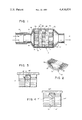
- FIG. 1 is an elevation view in cross section of a filter of the type contemplated.
- FIG. 2 is an enlarged segmentary view of a monolithic filter bed as shown in FIG. 1.
- FIG. 3 is an enlarged segmentary view in cross section of an alternate embodiment of the filter structure.
- FIG. 4 is similar to FIG. 3.
- a filter 10 of the type contemplated is illustrated and which comprises in essence a metallic housing or casing 11.
- the latter is preferably formed in circular cross section although it can as well assume a substantially oblong or other appropriate cross sectional area to conform with the shape of casing 11.
- a stream of hot exhaust diesel gas is introduced from an exhaust gas conduit 12 to one end of the filter 10, which defines a gas inlet 13.
- the opposed end of said casing 11 is comprised of an outlet 14 through which the substantially particle-free exhaust gas is permitted to flow.
- the gaseous stream, after being filtered can be introduced to the atmosphere. Alternatively it can be further treated by a muffler or the like connected downstream of filter 10.
- casing 11 which defines a central filter chamber 18, is provided at one end with a frusto conical member 15 which defines inlet 13 as well as diffusion chamber 16 at the upstream end of the filter bed series.
- filter casing 11 is provided with a frusto conical wall 17 into which the exhaust gas outlet 14 is formed.
- a series of thin filter beds 21, 22 and 23 are maintained longitudinally through the filter compartment by terminally disposed support panels 24 and 26.
- the latter can comprise a metallic mesh or screen member such as stainless steel or the like. Said members are positioned within the filter compartment to bear against end filter sections 21 and 23, and yet be pervious to the flow of exhaust gas.
- Casing 11 is normally formed of a metal such as steel having sufficient wall thickness to withstand the elevated temperature as well as the conditions under which it will normally function.
- the casing because of the excessive temperatures and variations thereof, will also be subjected to a certain amount of expansion and contraction. The latter action will occur in accordance with the phase of operation of the engine, and the temperature of the exhaust gas passing through the filter.
- Filter chamber 18 is provided as noted with a plurality of sequentially arranged filter beds 21, 22 and 23. The latter are disposed longitudinally through chamber 18, being spaced one from the other by a plurality of spacer rings 28 and 29.
- a turbulation chamber 31 defined by the spacer 28, as well as by the adjacent beds 21 and 22, is formed.
- the respective filter beds 21, 22 and 23 are longitudinally disposed and spaced, and comprise a disc-shaped monolith structured ceramic member which extends transversely across chamber 18.
- Such monolith structures are well known in the industry and are often used for the purpose of contacting a passing gas stream to achieve a filtering or other action on the gaseous stream.
- bed 21 for example, is comprised of a porous ceramic or refractory material having a skeletal structure.
- the structure in effect is comprised of a series of micro pores or passages which define a large number of horizontal gas passages 33.
- micro passages 33 can be provided with a catalytic material as well as with a layer of a base material.
- the porous skeletal structure of the filter bed 21 is provided with a coating of alumina.
- This layer can be applied in a number of ways although among the simplest is by immersing the uncoated bed into a solution of a suitable coating material. It is thus maintained immersed for a sufficient time to permit deposition of a desired alumina coating onto the various passage walls. This process is disclosed in U.S. Pat. No. 3,362,783, Leak et al.
- the thickness of the alumina is maintained sufficient to provide an adequate coating to the walls of each passage 33.
- the coating cannot seriously impede flow of gas passing therethrough by overly constricting the passage opening.
- the ceramic beds, 21 for example, were formed of a circular block of monolithic structured material having a diameter of about 6 inches.
- the respective beds 21, 22 and 23 were approximately 3/8 of an inch in length.
- Each of the serially aligned filter beds was separated from contiguous beds by an annular spacer ring 28.
- the latter member can be formed of a metal having a compatible expansion rate with the casing 11, as well as with the ceramic filter beds.
- ring 28 is provided with an internal opening sufficient to allow maximum gas flow through the respective beds.
- Spacer ring 28 can also be formed of a ceramic material compatible with that from which the beds 21, 22 and 23 were formed. Similarly, the ring can be provided particularly on its inner surface defined by the central opening 34, with a coating of a suitable material such as alumina whereby to improve the particle retention capabilities of the entire unit.
- the intermediate spaces such as turbulation chambers 31 defined between adjacent filter beds 21 and 22, permits exhaust gas which emerges from the respective passages 33 of the upstream bed, to expand slightly. This expansion will encourage a degree of turbulance to the gas. Thereafter, the gas upon traversing said turbulation chamber 31 will enter the next series of passages 33 in the subsequently positioned filter bed 22.
- the turbulation chamber 31 is provided with a frangible non-rigid filter media 32 such as steel wool or the like. Said media is compressed into turbulation chamber 31 in a manner that it will define randomly disposed passages through which the exhaust gas will pass.
- This non-rigid media 32 can be comprised as noted of metallic wires or fibrils wich can further be provided with a coating such as alumina or the like.
- the media 32 is therefore capable of retaining combustible particles from the exhaust gas stream.
- the width of turbulation chamber 31 is controlled by the width of spacer 28, the density of the filter media 32 within said chamber can be adjusted in accordance with the filtering capabilities desired. Further, the degree of turbulation which is to be provided to the gas passing through chamber 31 is of relevance. Thus, the amount of the steel wool which is initially inserted into turbulation chamber 31 during assembly of the filter, will determine the density of the said unit after the filter is completely assembled.
- the respective members are substantially as shown in FIG. 1.
- the periphery of ceramic filter bed 21', and the spacer ring 28', are maintained in a static condition by provision of a locking joint therebetween.
- Said peripheral locking joint can assume a number of embodiments.
- the present joint is comprised of an annular groove 36 which is formed into the peripheral face of ceramic block 28'. Said groove registers with a similarly shaped, or corresponding rim 37, which protrudes from the face of spacer ring 28'.
- the basic filter corresponds to that shown in FIg. 1.
- the outer edge of the media mass 32" can be compressed between the adjacent contacting surfaces of the respective filter block 21" and 22", and the spacer 28".
- spacer 28" is urged firmly into the contiguous surface of the filter bed 21", thereby squeezing the peripheral edge of the steel wool filter media 32" in such manner as to firmly retain the latter in place.
- This gripping at the peripheral edge will preclude the forming of undesired openings through which the gas could pass unfiltered.
- the filter unit can be provided with a sufficient number of beds 21.
- the latter is determined in accordance with the volume of gas which is to be treated, and with the amount of carbon or combustible particulate matter to be removed therefrom.
- the respective filter beds are inserted into casing 11 alternately with spacer rings 28 therebetween. After the spacers and the beds are firmly urged into place within casing 11, the end support screen, and the end wall are fastened in place to close the filter.
- the gas will be dispersed substantially across the face of initial filter bed 21 and traverse the filter bed passages 33. Upon entering the turbulation chamber, the gas will further pass through the tortuous passages defined by the steel wool media 32.
Abstract
Description
Claims (2)
Priority Applications (1)
| Application Number | Priority Date | Filing Date | Title |
|---|---|---|---|
| US06/360,707 US4416674A (en) | 1980-10-27 | 1982-03-22 | Filter for treating a particle-carrying gaseous stream |
Applications Claiming Priority (2)
| Application Number | Priority Date | Filing Date | Title |
|---|---|---|---|
| US20075480A | 1980-10-27 | 1980-10-27 | |
| US06/360,707 US4416674A (en) | 1980-10-27 | 1982-03-22 | Filter for treating a particle-carrying gaseous stream |
Related Parent Applications (1)
| Application Number | Title | Priority Date | Filing Date |
|---|---|---|---|
| US20075480A Continuation | 1980-10-27 | 1980-10-27 |
Publications (1)
| Publication Number | Publication Date |
|---|---|
| US4416674A true US4416674A (en) | 1983-11-22 |
Family
ID=26896066
Family Applications (1)
| Application Number | Title | Priority Date | Filing Date |
|---|---|---|---|
| US06/360,707 Expired - Fee Related US4416674A (en) | 1980-10-27 | 1982-03-22 | Filter for treating a particle-carrying gaseous stream |
Country Status (1)
| Country | Link |
|---|---|
| US (1) | US4416674A (en) |
Cited By (34)
| Publication number | Priority date | Publication date | Assignee | Title |
|---|---|---|---|---|
| WO1985002784A1 (en) * | 1983-12-27 | 1985-07-04 | Ford Motor Company | Apparatus for periodically oxidizing particulates collected from exhaust gases |
| US4544388A (en) * | 1983-12-27 | 1985-10-01 | Ford Motor Company | Apparatus for periodically oxidizing particulates collected from exhaust gases |
| US4556543A (en) * | 1980-07-24 | 1985-12-03 | Ngk Insulators, Ltd. | Ceramic honeycomb catalytic converters having high thermal shock resistance |
| WO1989002977A1 (en) * | 1987-10-02 | 1989-04-06 | Roberto Longobardi | Filter for the abatement of solid particles and unburned hydrocarbons entrained in the exhaust gases from internal combustion engines |
| EP0393257A1 (en) * | 1989-04-17 | 1990-10-24 | Emitec Gesellschaft für Emissionstechnologie mbH | Diesel soot filter with an additional arrangement for the reduction of nitrogen oxides and/or the oxidation of carbon monoxide |
| WO1990012950A1 (en) * | 1989-04-17 | 1990-11-01 | Emitec Gesellschaft Für Emissionstechnologie Mbh | Diesel-soot filter with additional device for reducing oxides of nitrogen and/or oxidizing carbon monoxide |
| US4985211A (en) * | 1987-10-26 | 1991-01-15 | Toyota Jidosha Kabushiki Kaisha | Exhaust gas processing apparatus for paint drying oven |
| US5014509A (en) * | 1989-12-27 | 1991-05-14 | Cummins Engine Company, Inc. | Diesel engine white smoke control system |
| US5294411A (en) * | 1989-04-17 | 1994-03-15 | Emitec Gesellschaft Fuer Emissionstechnologie Mbh | Honeycomb body with heatable catalytic active coating |
| US5387399A (en) * | 1991-12-26 | 1995-02-07 | Osaka Gas Co., Ltd. | Catalytic combustion apparatus |
| US5482685A (en) * | 1993-04-12 | 1996-01-09 | Matsushita Electric Industrial Co., Ltd. | Deodorizing apparatus |
| US5578277A (en) * | 1994-06-24 | 1996-11-26 | Caterpillar Inc. | Modular catalytic converter and muffler for internal combustion engine |
| US5849250A (en) * | 1997-02-03 | 1998-12-15 | Timko; Mark | Auxiliary catalytic converter having a back pressure relief device |
| WO2002057001A1 (en) * | 2001-01-19 | 2002-07-25 | Dullien, Inc. | Separator made of fibrous porous material, such as a felt |
| FR2821281A1 (en) * | 2001-02-28 | 2002-08-30 | Inst Francais Du Petrole | SEPARATOR OF POROUS MATERIAL COMPRISING A FELT STRUCTURE AND APPARATUS COMPRISING SUCH A SEPARATOR |
| WO2003068363A1 (en) * | 2002-02-12 | 2003-08-21 | Clean Diesel Technologies, Inc. | Multi-stage exhaust gas purifier |
| WO2004027289A1 (en) | 2002-09-20 | 2004-04-01 | The Gates Corporation | Belt tensioner |
| US20050223703A1 (en) * | 1992-06-02 | 2005-10-13 | Donaldson Company, Inc. | Muffler with catalytic converter arrangement; and method |
| US20060070375A1 (en) * | 2004-10-01 | 2006-04-06 | Blaisdell Jared D | Exhaust flow distribution device |
| US20060185352A1 (en) * | 2002-08-09 | 2006-08-24 | Johnson Matthey Pubic Limited Company | Exhaust system for a lean-burn ic engine |
| WO2006091135A1 (en) * | 2005-02-24 | 2006-08-31 | Volvo Technology Corporation | Particulate filter comprising first and second bodies arranged to create turbulance in a gas flow |
| US20060236680A1 (en) * | 2005-04-26 | 2006-10-26 | Wenzhong Zhang | Method for regenerating a diesel particulate filter |
| US20060236684A1 (en) * | 2005-04-26 | 2006-10-26 | Wenzhong Zhang | Diesel particulate matter reduction system |
| US20070234713A1 (en) * | 2006-04-03 | 2007-10-11 | Blaisdell Jared D | Exhaust flow distribution device |
| US20090242489A1 (en) * | 2008-03-28 | 2009-10-01 | Global Materials Technologies, Inc. | Element removal process and apparatus |
| WO2010059804A2 (en) * | 2008-11-19 | 2010-05-27 | Murray Kenneth D | Captured co2 from atmospheric, industrial and vehicle combustion waste |
| US7862640B2 (en) | 2006-03-21 | 2011-01-04 | Donaldson Company, Inc. | Low temperature diesel particulate matter reduction system |
| US20110114563A1 (en) * | 2008-03-28 | 2011-05-19 | Global Materials Technologies, Inc. | Element removal process and apparatus |
| WO2013041747A1 (en) * | 2011-09-23 | 2013-03-28 | Universidad Politécnica De Valencia | Device for treating exhaust gases from diesel turbo-supercharged reciprocating internal combustion engines (rice) |
| EP2753469A1 (en) * | 2011-09-06 | 2014-07-16 | Lantec Products, Inc. | Multi-segmented structured ceramic packing |
| CN106310823A (en) * | 2016-08-26 | 2017-01-11 | 中车株洲电机有限公司 | Dust suction box |
| CN106677865A (en) * | 2015-11-11 | 2017-05-17 | 赖宜铭 | Metal carrier and catalytic converter device for diesel engine |
| CN110159396A (en) * | 2019-07-04 | 2019-08-23 | 天津大学 | Segmented filter core and its engine particulate trap |
| CN111238283A (en) * | 2020-01-19 | 2020-06-05 | 无锡苏胜尔机械设备有限公司 | Combined preheater with air filtering function |
Citations (12)
| Publication number | Priority date | Publication date | Assignee | Title |
|---|---|---|---|---|
| US2132940A (en) * | 1934-12-22 | 1938-10-11 | Westinghouse Air Brake Co | Air strainer |
| US3105570A (en) * | 1962-04-17 | 1963-10-01 | Bezemes Nicholas | Internal combustion engine exhaust muffler |
| US3163256A (en) * | 1962-06-06 | 1964-12-29 | Corning Glass Works | Muffler with ceramic honeycomb baffle |
| US3623295A (en) * | 1969-05-02 | 1971-11-30 | Walter Shriner | Air pollution reduction system |
| US3754870A (en) * | 1971-08-26 | 1973-08-28 | Universal Oil Prod Co | Method and means of catalytically converting fluids |
| US3771967A (en) * | 1971-12-14 | 1973-11-13 | Tenneco Inc | Catalytic reactor with monolithic element |
| US3802163A (en) * | 1972-08-23 | 1974-04-09 | G Riojas | Internal combustion engine mufflers |
| US3852042A (en) * | 1973-01-29 | 1974-12-03 | Universal Oil Prod Co | Catalytic converter with exhaust gas modulating chamber for preventing damage to catalyst substrate |
| US3860403A (en) * | 1971-12-14 | 1975-01-14 | Katashi Aoi | Exhaust gas purifying apparatus for internal combustion engines |
| US4224285A (en) * | 1978-04-05 | 1980-09-23 | Texaco Inc. | Smoke filter for internal combustion engines |
| US4264346A (en) * | 1979-12-12 | 1981-04-28 | General Motors Corporation | Diesel exhaust particulate traps |
| US4346557A (en) * | 1980-05-07 | 1982-08-31 | General Motors Corporation | Incineration-cleanable composite diesel exhaust filter and vehicle equipped therewith |
-
1982
- 1982-03-22 US US06/360,707 patent/US4416674A/en not_active Expired - Fee Related
Patent Citations (12)
| Publication number | Priority date | Publication date | Assignee | Title |
|---|---|---|---|---|
| US2132940A (en) * | 1934-12-22 | 1938-10-11 | Westinghouse Air Brake Co | Air strainer |
| US3105570A (en) * | 1962-04-17 | 1963-10-01 | Bezemes Nicholas | Internal combustion engine exhaust muffler |
| US3163256A (en) * | 1962-06-06 | 1964-12-29 | Corning Glass Works | Muffler with ceramic honeycomb baffle |
| US3623295A (en) * | 1969-05-02 | 1971-11-30 | Walter Shriner | Air pollution reduction system |
| US3754870A (en) * | 1971-08-26 | 1973-08-28 | Universal Oil Prod Co | Method and means of catalytically converting fluids |
| US3771967A (en) * | 1971-12-14 | 1973-11-13 | Tenneco Inc | Catalytic reactor with monolithic element |
| US3860403A (en) * | 1971-12-14 | 1975-01-14 | Katashi Aoi | Exhaust gas purifying apparatus for internal combustion engines |
| US3802163A (en) * | 1972-08-23 | 1974-04-09 | G Riojas | Internal combustion engine mufflers |
| US3852042A (en) * | 1973-01-29 | 1974-12-03 | Universal Oil Prod Co | Catalytic converter with exhaust gas modulating chamber for preventing damage to catalyst substrate |
| US4224285A (en) * | 1978-04-05 | 1980-09-23 | Texaco Inc. | Smoke filter for internal combustion engines |
| US4264346A (en) * | 1979-12-12 | 1981-04-28 | General Motors Corporation | Diesel exhaust particulate traps |
| US4346557A (en) * | 1980-05-07 | 1982-08-31 | General Motors Corporation | Incineration-cleanable composite diesel exhaust filter and vehicle equipped therewith |
Cited By (54)
| Publication number | Priority date | Publication date | Assignee | Title |
|---|---|---|---|---|
| US4556543A (en) * | 1980-07-24 | 1985-12-03 | Ngk Insulators, Ltd. | Ceramic honeycomb catalytic converters having high thermal shock resistance |
| WO1985002784A1 (en) * | 1983-12-27 | 1985-07-04 | Ford Motor Company | Apparatus for periodically oxidizing particulates collected from exhaust gases |
| US4544388A (en) * | 1983-12-27 | 1985-10-01 | Ford Motor Company | Apparatus for periodically oxidizing particulates collected from exhaust gases |
| WO1989002977A1 (en) * | 1987-10-02 | 1989-04-06 | Roberto Longobardi | Filter for the abatement of solid particles and unburned hydrocarbons entrained in the exhaust gases from internal combustion engines |
| US4985211A (en) * | 1987-10-26 | 1991-01-15 | Toyota Jidosha Kabushiki Kaisha | Exhaust gas processing apparatus for paint drying oven |
| WO1990012950A1 (en) * | 1989-04-17 | 1990-11-01 | Emitec Gesellschaft Für Emissionstechnologie Mbh | Diesel-soot filter with additional device for reducing oxides of nitrogen and/or oxidizing carbon monoxide |
| US5294411A (en) * | 1989-04-17 | 1994-03-15 | Emitec Gesellschaft Fuer Emissionstechnologie Mbh | Honeycomb body with heatable catalytic active coating |
| EP0393257A1 (en) * | 1989-04-17 | 1990-10-24 | Emitec Gesellschaft für Emissionstechnologie mbH | Diesel soot filter with an additional arrangement for the reduction of nitrogen oxides and/or the oxidation of carbon monoxide |
| US5014509A (en) * | 1989-12-27 | 1991-05-14 | Cummins Engine Company, Inc. | Diesel engine white smoke control system |
| US5387399A (en) * | 1991-12-26 | 1995-02-07 | Osaka Gas Co., Ltd. | Catalytic combustion apparatus |
| US5505910A (en) * | 1991-12-26 | 1996-04-09 | Osaka Gas Co., Ltd. | Catalytic combustion apparatus |
| US20050223703A1 (en) * | 1992-06-02 | 2005-10-13 | Donaldson Company, Inc. | Muffler with catalytic converter arrangement; and method |
| US5482685A (en) * | 1993-04-12 | 1996-01-09 | Matsushita Electric Industrial Co., Ltd. | Deodorizing apparatus |
| US5578277A (en) * | 1994-06-24 | 1996-11-26 | Caterpillar Inc. | Modular catalytic converter and muffler for internal combustion engine |
| US5849250A (en) * | 1997-02-03 | 1998-12-15 | Timko; Mark | Auxiliary catalytic converter having a back pressure relief device |
| WO2002057001A1 (en) * | 2001-01-19 | 2002-07-25 | Dullien, Inc. | Separator made of fibrous porous material, such as a felt |
| US7708794B2 (en) | 2001-02-28 | 2010-05-04 | Institut Francais Du Petrole | Separator made of a fibrous porous material such as a felt |
| FR2821281A1 (en) * | 2001-02-28 | 2002-08-30 | Inst Francais Du Petrole | SEPARATOR OF POROUS MATERIAL COMPRISING A FELT STRUCTURE AND APPARATUS COMPRISING SUCH A SEPARATOR |
| US20040103627A1 (en) * | 2001-02-28 | 2004-06-03 | Dullien Francis A. L. | Separator made of a fibrous porous material such as a felt |
| WO2003068363A1 (en) * | 2002-02-12 | 2003-08-21 | Clean Diesel Technologies, Inc. | Multi-stage exhaust gas purifier |
| US20060185352A1 (en) * | 2002-08-09 | 2006-08-24 | Johnson Matthey Pubic Limited Company | Exhaust system for a lean-burn ic engine |
| WO2004027289A1 (en) | 2002-09-20 | 2004-04-01 | The Gates Corporation | Belt tensioner |
| US20060070375A1 (en) * | 2004-10-01 | 2006-04-06 | Blaisdell Jared D | Exhaust flow distribution device |
| US7997071B2 (en) | 2004-10-01 | 2011-08-16 | Donaldson Company, Inc. | Exhaust flow distribution device |
| US20090031717A1 (en) * | 2004-10-01 | 2009-02-05 | Donaldson Company, Inc. | Exhaust flow distribution device |
| US7451594B2 (en) | 2004-10-01 | 2008-11-18 | Donaldson Company, Inc. | Exhaust flow distribution device |
| WO2006091135A1 (en) * | 2005-02-24 | 2006-08-31 | Volvo Technology Corporation | Particulate filter comprising first and second bodies arranged to create turbulance in a gas flow |
| US7340888B2 (en) | 2005-04-26 | 2008-03-11 | Donaldson Company, Inc. | Diesel particulate matter reduction system |
| US20060236680A1 (en) * | 2005-04-26 | 2006-10-26 | Wenzhong Zhang | Method for regenerating a diesel particulate filter |
| US20090235649A1 (en) * | 2005-04-26 | 2009-09-24 | Donaldson Company, Inc. | Method for Regenerating a Diesel Particulate Filter |
| US20060236684A1 (en) * | 2005-04-26 | 2006-10-26 | Wenzhong Zhang | Diesel particulate matter reduction system |
| US7861521B2 (en) | 2005-04-26 | 2011-01-04 | Donaldson Company, Inc. | Method for regenerating a diesel particulate filter |
| US8808418B2 (en) | 2006-03-21 | 2014-08-19 | Donaldson Company | Low temperature diesel particulate matter reduction system |
| US7862640B2 (en) | 2006-03-21 | 2011-01-04 | Donaldson Company, Inc. | Low temperature diesel particulate matter reduction system |
| US8470253B2 (en) | 2006-04-03 | 2013-06-25 | Donaldson Company, Inc. | Exhaust flow distribution device |
| US8110151B2 (en) | 2006-04-03 | 2012-02-07 | Donaldson Company, Inc. | Exhaust flow distribution device |
| US20070234713A1 (en) * | 2006-04-03 | 2007-10-11 | Blaisdell Jared D | Exhaust flow distribution device |
| US8025800B2 (en) * | 2008-03-28 | 2011-09-27 | Global Material Technologies, Inc. | Element removal apparatus |
| US20110114563A1 (en) * | 2008-03-28 | 2011-05-19 | Global Materials Technologies, Inc. | Element removal process and apparatus |
| US20090242489A1 (en) * | 2008-03-28 | 2009-10-01 | Global Materials Technologies, Inc. | Element removal process and apparatus |
| WO2010059804A3 (en) * | 2008-11-19 | 2010-08-19 | Murray Kenneth D | Captured co2 from atmospheric, industrial and vehicle combustion waste |
| CN102282343B (en) * | 2008-11-19 | 2014-12-17 | K·D·默里 | Captured Co2 from atmospheric, industrial and vehicle combustion waste |
| US20100251937A1 (en) * | 2008-11-19 | 2010-10-07 | Murray Kenneth D | Captured co2 from atmospheric, industrial and vehicle combustion waste |
| CN102282343A (en) * | 2008-11-19 | 2011-12-14 | K·D·默里 | Captured Co2 from atmospheric, industrial and vehicle combustion waste |
| WO2010059804A2 (en) * | 2008-11-19 | 2010-05-27 | Murray Kenneth D | Captured co2 from atmospheric, industrial and vehicle combustion waste |
| US7914758B2 (en) | 2008-11-19 | 2011-03-29 | Murray Kenneth D | Captured CO2 from atmospheric, industrial and vehicle combustion waste |
| EP2753469A1 (en) * | 2011-09-06 | 2014-07-16 | Lantec Products, Inc. | Multi-segmented structured ceramic packing |
| EP2753469A4 (en) * | 2011-09-06 | 2015-02-25 | Lantec Products Inc | Multi-segmented structured ceramic packing |
| WO2013041747A1 (en) * | 2011-09-23 | 2013-03-28 | Universidad Politécnica De Valencia | Device for treating exhaust gases from diesel turbo-supercharged reciprocating internal combustion engines (rice) |
| CN106677865A (en) * | 2015-11-11 | 2017-05-17 | 赖宜铭 | Metal carrier and catalytic converter device for diesel engine |
| CN106310823A (en) * | 2016-08-26 | 2017-01-11 | 中车株洲电机有限公司 | Dust suction box |
| CN110159396A (en) * | 2019-07-04 | 2019-08-23 | 天津大学 | Segmented filter core and its engine particulate trap |
| CN111238283A (en) * | 2020-01-19 | 2020-06-05 | 无锡苏胜尔机械设备有限公司 | Combined preheater with air filtering function |
| CN111238283B (en) * | 2020-01-19 | 2021-08-24 | 无锡苏胜尔机械设备有限公司 | Combined preheater with air filtering function |
Similar Documents
| Publication | Publication Date | Title |
|---|---|---|
| US4416674A (en) | Filter for treating a particle-carrying gaseous stream | |
| US5065576A (en) | Exhaust gas purifying device for a diesel engine | |
| KR100595407B1 (en) | Particulate matter reducing apparatus | |
| US5248481A (en) | Diesel particulate trap of perforated tubes having laterally offset cross-wound wraps of inorganic yarn | |
| US7273514B2 (en) | Apparatus and method for filtering particulate and NOx emissions | |
| CN101801499A (en) | Stop up by selectivity and to adjust the particulate filter performance and use a plurality of particulate filters to reduce discharging and improve hear resistance | |
| US5560757A (en) | Exhaust particulate filter for diesel engine | |
| US4869738A (en) | Particulate trap | |
| JPH0729013B2 (en) | Granular material trap assembly and method of manufacturing the same | |
| JPH0380962B2 (en) | ||
| JPH0617643B2 (en) | Waste gas purifier for diesel engine | |
| JP2011214577A (en) | Process and device for removing soot particle from diesel engine exhaust gas | |
| JPH04279714A (en) | Exhaust filter for internal combustion engine | |
| US4423090A (en) | Method of making wall-flow monolith filter | |
| JPH10176519A (en) | Particulate trap for diesel engine | |
| US4039294A (en) | Filter for internal combustion exhaust gases | |
| US20040065079A1 (en) | Method and device for aftertreatment exhaust gases from combustion engines | |
| US4600562A (en) | Method and apparatus for filtering engine exhaust gas | |
| CA1176822A (en) | Bifunctional filter for the treatment of exhaust gases | |
| US4712643A (en) | Particulate trap exhaust muffler | |
| JPH0647620U (en) | Exhaust gas purification device | |
| JPH0261313A (en) | Structure for purifying exhaust gas | |
| EP1251249B2 (en) | A process and device for removing soot particles from the exhaust gas from a diesel engine | |
| JP4048926B2 (en) | Exhaust particulate filter for internal combustion engine | |
| JP2671616B2 (en) | Exhaust filter for internal combustion engine |
Legal Events
| Date | Code | Title | Description |
|---|---|---|---|
| MAFP | Maintenance fee payment |
Free format text: PAYMENT OF MAINTENANCE FEE, 4TH YEAR, PL 96-517 (ORIGINAL EVENT CODE: M170); ENTITY STATUS OF PATENT OWNER: LARGE ENTITY Year of fee payment: 4 |
|
| FEPP | Fee payment procedure |
Free format text: PAYOR NUMBER ASSIGNED (ORIGINAL EVENT CODE: ASPN); ENTITY STATUS OF PATENT OWNER: LARGE ENTITY |
|
| FEPP | Fee payment procedure |
Free format text: MAINTENANCE FEE REMINDER MAILED (ORIGINAL EVENT CODE: REM.); ENTITY STATUS OF PATENT OWNER: LARGE ENTITY |
|
| LAPS | Lapse for failure to pay maintenance fees | ||
| FP | Lapsed due to failure to pay maintenance fee |
Effective date: 19911124 |
|
| STCH | Information on status: patent discontinuation |
Free format text: PATENT EXPIRED DUE TO NONPAYMENT OF MAINTENANCE FEES UNDER 37 CFR 1.362 |