US4416957A - Electrochemical cell - Google Patents
Electrochemical cell Download PDFInfo
- Publication number
- US4416957A US4416957A US06/354,276 US35427682A US4416957A US 4416957 A US4416957 A US 4416957A US 35427682 A US35427682 A US 35427682A US 4416957 A US4416957 A US 4416957A
- Authority
- US
- United States
- Prior art keywords
- cell
- active element
- electrolytic solution
- during discharge
- active
- Prior art date
- Legal status (The legal status is an assumption and is not a legal conclusion. Google has not performed a legal analysis and makes no representation as to the accuracy of the status listed.)
- Expired - Lifetime
Links
Images
Classifications
-
- H—ELECTRICITY
- H01—ELECTRIC ELEMENTS
- H01M—PROCESSES OR MEANS, e.g. BATTERIES, FOR THE DIRECT CONVERSION OF CHEMICAL ENERGY INTO ELECTRICAL ENERGY
- H01M6/00—Primary cells; Manufacture thereof
- H01M6/14—Cells with non-aqueous electrolyte
-
- H—ELECTRICITY
- H01—ELECTRIC ELEMENTS
- H01M—PROCESSES OR MEANS, e.g. BATTERIES, FOR THE DIRECT CONVERSION OF CHEMICAL ENERGY INTO ELECTRICAL ENERGY
- H01M4/00—Electrodes
- H01M4/02—Electrodes composed of, or comprising, active material
- H01M4/06—Electrodes for primary cells
- H01M4/08—Processes of manufacture
- H01M4/12—Processes of manufacture of consumable metal or alloy electrodes
-
- H—ELECTRICITY
- H01—ELECTRIC ELEMENTS
- H01M—PROCESSES OR MEANS, e.g. BATTERIES, FOR THE DIRECT CONVERSION OF CHEMICAL ENERGY INTO ELECTRICAL ENERGY
- H01M6/00—Primary cells; Manufacture thereof
- H01M6/50—Methods or arrangements for servicing or maintenance, e.g. for maintaining operating temperature
- H01M6/5044—Cells or batteries structurally combined with cell condition indicating means
- H01M6/5055—End of discharge indicated by a voltage step
Definitions
- the present invention relates to an electrochemical cell and, more particularly, to a primary electrochemical cell operative to provide a warning indication toward the end of discharge of the cell signalling an approaching end-of-life of the cell.
- Primary electrochemical cells are generally well known and available in a variety of sizes and shapes.
- One well known form of a primary electrochemical cell is a cylindrical cell including a battery stack disposed within a generally cylindrical metal housing and exposed to and permeated by an electrolytic solution.
- U.S. Pat. No. 4,060,668 in the name of Franz Goebel and assigned to GTE Laboratories Incorporated, discloses a cylindrical primary electrochemical cell having a battery stack including a lithium anode, a carbon current collector cathode structure, and a separator of insulative material interposed between the lithium anode and the carbon current collector cathode structure.
- a lithium/thionyl chloride cell in which the electrochemically active components of the cell, including the electrolytic solution, are selected so that the electrolytic solution is exhausted during discharge before the other active components.
- a detectable step or transition occurs in the output voltage of the cell which serves as an indication of impending cell discharge.
- a disadvantage of the cell design of this latter patent is that the limiting of the amount of electrolytic solution makes less of the electrolytic solution available for absorbing soluble gaseous discharge products, such as sulfur dioxide, with the result that an undesirable increase in internal cell pressure may occur.
- the anode structure in accordance with the invention includes first and second active elements.
- the first active element is of a first material having a first oxidation potential within the cell and is consumed by electrochemical action within the cell during discharge of the cell as a result of which a first value of operating voltage for the cell is established during the discharge of the cell and the consumption of the first active element.
- the second active element is of a second material having a second oxidation potential within the cell and is consumed by electrochemical action within the cell during discharge of the cell as a result of which a second, different value of operating voltage for the cell is established during the discharge of the cell and the consumption of the second active element.
- the first and second active elements are arranged with respect to each other in accordance with the invention so that one of the active elements is consumed before the other whereby the value of operating voltage of the cell changes from one of its two values to the other of its two values. This change in the value of the operating voltage may be utilized as an end-of-life indication.
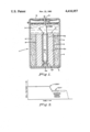
- FIG. 1 is an elevational view, partly in cross section and with portions exaggerated for the sake of clarity, of a cylindrical primary electrochemical cell in accordance with the invention capable of providing a warning condition toward the end of discharge of the cell signalling an approaching end-of-life of the cell;
- FIG. 2 is a discharge curve of operating voltage versus time for the cell of FIG. 1 illustrating the occurrence of the warning condition representing the approaching end-of-life of the cell.
- the cell 1 is of a general type as described in the aforementioned co-pending application Ser. No. 333,094 and, as shown in FIG. 1, includes a battery stack 2 employed together with an electrolytic solution 3 within an elongated cylindrical metal casing or housing 4 of the cell 1.
- the battery stack 2 and the electrolytic solution 3 collectively represent the electrochemical system of the cell.
- the battery stack 2 employed within the cell 1 is insulated from the housing of the cell by a suitable porous insulator 5 (e.g., of glass paper), and generally includes a concentric arrangement of a porous carbon cathode structure 6, a thin porous separator 8, and an anode structure 10.
- the anode structure 10 is constructed in accordance with the invention so as to alter the operating voltage of the cell 1 as the end of the life of the cell approaches, thereby to provide a warning condition signalling the approaching end-of-life of the cell.
- the porous carbon cathode structure 6 is a generally cylindrical, elongated tubular member comprising an aggregation of discrete, semi-rigid, porous carbon conglomerates. These conglomerates generally contain a combination of carbon black and a binder such as "Teflon".
- the carbon cathode structure 6 may be formed from the conglomerates into a single-piece component as shown in FIG. 1 or, alternatively, the carbon cathode structure 6 may be constructed of a pre-selected number of individual annular or "donut" shaped discs superimposed upon each other in a vertical stacked array to effectively form a single carbon cathode structure of essentially any desired overall length.
- Suitable approximate dimensions for the carbon cathode structure 6 for an AA-size cell are a length of 1.5 inch, an outside diameter of 0.5 inch, and an inside diameter of 0.3 inch. Because of the porous nature of the constituent components of the conglomerates used to form the carbon cathode structure 6, the carbon cathode structure 6 has a resultant network of electrolyte-conducting channels formed therein whereby the carbon cathode structure 6 can be readily permeated by the electrolytic solution 3. Techniques for producing the conglomerates employed by the carbon cathode structure 6 are generally described in U.S. Pat. No. 4,161,063 to which reference may be made for specific details.
- the aforementioned porous separator 8 is disposed intermediate to the carbon cathode structure 6 and the anode structure 10 and is used to electrically isolate the carbon cathode structure 6 from the anode structure 10.
- the separator 8 typically takes the form of a cylindrical sheet of a standard, electrically nonconductive material such as glass paper.
- the anode structure 10 as utilized within the cell 1 is located centrally within the cell 1 and, as shown in FIG. 1, generally includes a solid, elongated, cylindrical electrode 10a of a first consumable active metal; an elongated electrically-nonconductive member 10c disposed within the electrode 10a and having a necked-down portion 10e of a diameter and cross section less than the rest of the member 10c; an element 10f of a second consumable active metal and disposed on the member 10c adjacent to the necked-down portion 10e of the member 10c and completely surrounded by the material of the metal electrode 10a; an electrically-conductive terminal element 10g disposed on the member 10c within the electrode 10a and in physical and electrical contact with the consumable metal electrode 10a and the consumable element 10f; and a thin, flexible, electrically-conductive metal jumper element 10h physically and electrically connected between the electrically-conductive terminal element 10g and an elongated, hollow, metal feedthrough member 12.
- the electrode 10a of the anode structure 10 is typically of an oxidizable active consumable alkali metal such as lithium, which has a high oxidation potential, for example, 3.68 volts (in thionyl chloride). Suitable approximate dimensions for the electrode 10a are a length of 1.5 inch and an outside diameter of approximately 0.3 inch.
- the aforementioned electrically-nonconductive member 10c may take the form of a hollow glass or ceramic tube as shown in FIG. 1 or a glass or ceramic rod.
- the tube form of the member 10c may be preferred for many applications in which it is desired to provide an additional amount of electrolytic solution in the cell, for example, to increase the efficiency of utilization (depletion) of the consumable metals in the cell.
- the hollow tube serves as a simple and convenient reservoir or cavity for the retention therein of the additional or excess amount of electrolytic solution.
- Suitable approximate dimensions for the member 10c are a length of 1.5 inch, an outside diameter of 0.080 inch for the necked-down portion 10e, a diameter of 0.125 inch for the rest of its length, and a wall thickness (for a hollow tube) of 0.04 inch.
- the aforementioned active element 10f disposed on the member 10c adjacent to the necked-down portion 10e typically takes the form of a ring and is typically of an oxidizable active consumable alkaline earth metal such as calcium, which has a lower oxidation potential than the lithium electrode 10a, for example, 3.0 volts (in thionyl chloride).
- a suitable diameter for the element 10f is 0.125 inch and a suitable thickness therefor is 0.020 inch.
- calcium is the present preferred material for the active element 10f, other possible materials may also be used for the active element 10f, for example, alloys of alkali metals such as lithium aluminum alloys and lithium boron alloys having suitable oxidation potentials compatible with the lithium metal of the electrode 10a.
- the aforementioned electrically-conductive terminal element 10g disposed on the member 10c may take the form of an electrically-conductive non-consumable metal coating or, alternatively, an elongated, thin, non-consumable metal wire or strip wound or wrapped about the upper portion of the member 10c.
- a suitable material for the metal coating or wire or strip is nickel, and a suitable thickness therefor is 0.005 inch.
- the aforementioned jumper element 10h may be of nickel and in the form of a wire or flat ribbon, and may be secured to the electrically-conductive terminal element 10g in any suitable manner.
- a first end of the jumper element 10h may simply be welded directly to the terminal element 10g or, alternatively, embedded together with the terminal element 10g within the lithium electrode 10a as generally indicated in FIG. 1.
- the other end of the jumper element 10h is secured, as by welding, to the aforementioned cylindrical, hollow, metal (e.g., nickel) feedthrough member 12.
- the feedthrough member itself passes through a standard insulative glass or ceramic-to-metal seal 14 provided within an hermetically sealed metal cap or cover 15 of the cell 1.
- the jumper element 10h by virtue of its non-rigid, flexible nature and small thickness, for example, 0.005-0.015 inch, serves to absorb any shock or vibration to which the cell 1 might be exposed, thereby to prevent a break in the physical and electrical connection between the electrically-conductive terminal element 10g and the feedthrough member 12, and also to minimize the possibility of physical damage (e.g., breakage) to the glass or ceramic-to-metal seal 14 due to such factors as shock and vibration.
- a suitable and preferred electrolytic solution 3 which may be used with the above-described cell 1 is a cathodelectrolyte solution including a reducible soluble cathode, such as thionyl chloride, and an electrolyte solute, such as lithium tetrachloroaluminate, dissolved in the thionyl chloride.
- a reducible soluble cathode such as thionyl chloride
- an electrolyte solute such as lithium tetrachloroaluminate
- the reducible soluble cathode namely, the thionyl chloride
- the thionyl chloride is catalytically reduced at the surface of the carbon cathode structure 6.
- the catalytic reduction results, inter alia, in the formation of a variety of reaction products within the cell and, as determined by the rate of this catalytic reduction, a gradual depletion of both of the active metals, i.e., the lithium and calcium, and also a depletion of the thionyl chloride.
- the lithium and calcium metals are selected quantitatively relative to the electrolytic solution 3 so as to be depleted prior to the depletion of the thionyl chloride in the electrolytic solution.
- the transition from the depletion of the lithium to the calcium occurs toward the end of the life of the cell and results in a drop in operating voltage of the cell due to the lower oxidation potential for the calcium than the lithium.
- This drop in voltage is depicted in FIG. 2 and is utilized, until such time as all of the calcium has been depleted, to represent a warning signal period indicating the approaching or impending end-of-life of the cell.
- This period may also be used to initiate some other action, for example, switching a load (not shown) powered by the cell to a standby cell or activating external circuitry.
- the period effectively ends when all of the calcium has been depleted (which depends on the amount of the calcium), thereby effectively marking the end of the useful or rated life span of the cell.
- the drop in operating voltage of the cell 1 as described hereinabove is clear and unambiguous and capable of being detected and monitored to allow sufficient time for replacing the cell or initiating other appropriate action. Further, during the warning period, the operating voltage of the cell 1 is still large enough, for example, about 3.0 volts, to ensure that a load connected across and powered by the cell continues to be supplied with ample voltage for ensuring its continued operation.
Abstract
Description
Claims (12)
Priority Applications (5)
| Application Number | Priority Date | Filing Date | Title |
|---|---|---|---|
| US06/354,276 US4416957A (en) | 1982-03-03 | 1982-03-03 | Electrochemical cell |
| PCT/US1983/000200 WO1983003169A1 (en) | 1982-03-03 | 1983-02-14 | Electrochemical cell having end-of-life warning means |
| EP83901032A EP0102382B1 (en) | 1982-03-03 | 1983-02-14 | Electrochemical cell having end-of-life warning means |
| DE8383901032T DE3377317D1 (en) | 1982-03-03 | 1983-02-14 | Electrochemical cell having end-of-life warning means |
| DK500183A DK164146C (en) | 1982-03-03 | 1983-11-01 | ELECTROCHEMICAL ELEMENT WITH ANNOUNCEMENT OF END OF LIFE |
Applications Claiming Priority (1)
| Application Number | Priority Date | Filing Date | Title |
|---|---|---|---|
| US06/354,276 US4416957A (en) | 1982-03-03 | 1982-03-03 | Electrochemical cell |
Publications (1)
| Publication Number | Publication Date |
|---|---|
| US4416957A true US4416957A (en) | 1983-11-22 |
Family
ID=23392584
Family Applications (1)
| Application Number | Title | Priority Date | Filing Date |
|---|---|---|---|
| US06/354,276 Expired - Lifetime US4416957A (en) | 1982-03-03 | 1982-03-03 | Electrochemical cell |
Country Status (5)
| Country | Link |
|---|---|
| US (1) | US4416957A (en) |
| EP (1) | EP0102382B1 (en) |
| DE (1) | DE3377317D1 (en) |
| DK (1) | DK164146C (en) |
| WO (1) | WO1983003169A1 (en) |
Cited By (13)
| Publication number | Priority date | Publication date | Assignee | Title |
|---|---|---|---|---|
| US4515873A (en) * | 1983-07-28 | 1985-05-07 | Cordis Corporation | Lithium cell having continuous depletion gauge |
| US4560628A (en) * | 1984-09-21 | 1985-12-24 | The United States Of America As Represented By The Secretary Of The Army | High capacity inorganic oxyhalide electrochemical cell |
| US4563401A (en) * | 1983-08-08 | 1986-01-07 | Battery Engineering, Inc. | Electrochemical cell with adjustable step-like output voltage |
| US5416403A (en) * | 1993-02-11 | 1995-05-16 | Hewlett-Packard Corporation | Current stabilizing circuit |
| US5418086A (en) * | 1993-08-09 | 1995-05-23 | Eveready Battery Company, Inc. | Battery with coulometric state of charge indicator |
| US5485090A (en) * | 1993-02-11 | 1996-01-16 | Hewlett-Packard Corporation | Method and apparatus for differentiating battery types |
| US5489835A (en) * | 1993-02-11 | 1996-02-06 | Hewlett-Packard Company | Cell type determination of battery under charge conditions |
| US5569553A (en) * | 1995-03-08 | 1996-10-29 | Wilson Greatbatch Ltd. | Battery design for achieving end-of-life indication during electrical discharge |
| EP0891000A2 (en) * | 1997-07-08 | 1999-01-13 | Geco A.S. | A novel method to determine the state of charge and remaining life of lithium batteries used in oilfield services applications |
| US6761744B1 (en) | 1999-07-16 | 2004-07-13 | Quallion Llc | Lithium thin film lamination technology on electrode to increase battery capacity |
| US8067108B1 (en) | 2007-02-14 | 2011-11-29 | Electrochem Solutions, Inc. | Hybrid battery for use over extended temperature range |
| US8445137B1 (en) | 2002-11-27 | 2013-05-21 | Quallion Llc | Primary battery having sloped voltage decay |
| US10727486B2 (en) | 2014-12-12 | 2020-07-28 | Electrochem Solutions, Inc. | Lithium oxyhalide electrochemical cell with carbon monofluoride |
Families Citing this family (1)
| Publication number | Priority date | Publication date | Assignee | Title |
|---|---|---|---|---|
| IT231088Y1 (en) * | 1993-02-17 | 1999-07-12 | Finvetro Srl | CONTROL DEVICE FOR A VENETIAN BLIND OR SIMILAR INSIDE A GLAZING |
Citations (7)
| Publication number | Priority date | Publication date | Assignee | Title |
|---|---|---|---|---|
| US4025700A (en) * | 1974-04-05 | 1977-05-24 | P. R. Mallory & Co., Inc. | Variable precision multivoltage step battery |
| US4132836A (en) * | 1977-11-21 | 1979-01-02 | Eleanor & Wilson Greatbatch Foundation | Alkali metal-halogen cell having mixed halogen cathode |
| US4247606A (en) * | 1977-06-20 | 1981-01-27 | Hitachi Maxell, Ltd. | Silver oxide cell and its manufacture |
| US4247607A (en) * | 1980-04-28 | 1981-01-27 | Catalyst Research Corporation | Lithium halide primary cell having end of life indicator means |
| US4293622A (en) * | 1979-12-17 | 1981-10-06 | Battery Engineering, Inc. | Step cell |
| US4371592A (en) * | 1980-03-28 | 1983-02-01 | Gipelec | Primary cell of high energy density in which the anode active material is an alkali metal |
| US4375502A (en) * | 1980-05-07 | 1983-03-01 | Societe Anonyme Dite: Gipelec | Electrolyte for a lithium/thionyl chloride electric cell, a method of preparing said electrolyte and an electric cell which includes said electrolyte |
Family Cites Families (10)
| Publication number | Priority date | Publication date | Assignee | Title |
|---|---|---|---|---|
| US3757793A (en) * | 1971-11-15 | 1973-09-11 | Medtronic Inc | Electrochemical cell with stepped voltage output |
| NL174508C (en) * | 1972-08-04 | 1984-01-16 | Du Pont | METHOD OF MANUFACTURING A COMPOSITE ELECTRICAL CONDUCTIVE COATING, CONTAINING A METALLIC BASIS AND AN ELECTRICALLY CONDUCTIVE COATING ON THIS, AND A GALVANIC CELL IN WHICH ONE OR MORE OF THESE ELECTRODES ARE PLACED. |
| US4060668A (en) * | 1975-01-09 | 1977-11-29 | Gte Laboratories Incorporated | Primary electrochemical cell |
| JPS53103127A (en) * | 1977-02-21 | 1978-09-08 | Seiko Instr & Electronics | Alkaline battery |
| DE2734721A1 (en) * | 1977-08-02 | 1979-02-15 | Varta Batterie | Electronic wrist watch - using battery providing lower voltage triggering liq. crystal indicator when battery is exhausted |
| US4093784A (en) * | 1977-08-26 | 1978-06-06 | The United States Of America As Represented By The Secretary Of The Army | Lithium primary cell |
| DK155559C (en) * | 1979-06-27 | 1989-10-16 | Eveready Battery Inc | NON-ELECTRICAL ELECTROCHEMICAL ELEMENT |
| DE3027309A1 (en) * | 1980-07-18 | 1982-02-18 | Tadiran Israel Electronics Industries Ltd., Tel Aviv | High power lithium cell with wound electrode - has reduced electrolyte concn. or activity or alloyed lithium electrode to prevent explosion after short circuit |
| US4318969A (en) * | 1980-11-21 | 1982-03-09 | Gte Laboratories Incorporated | Electrochemical cell |
| US4450213A (en) * | 1982-01-18 | 1984-05-22 | Duracell Inc. | Cell having improved abuse resistance |
-
1982
- 1982-03-03 US US06/354,276 patent/US4416957A/en not_active Expired - Lifetime
-
1983
- 1983-02-14 WO PCT/US1983/000200 patent/WO1983003169A1/en active IP Right Grant
- 1983-02-14 DE DE8383901032T patent/DE3377317D1/en not_active Expired
- 1983-02-14 EP EP83901032A patent/EP0102382B1/en not_active Expired
- 1983-11-01 DK DK500183A patent/DK164146C/en not_active IP Right Cessation
Patent Citations (7)
| Publication number | Priority date | Publication date | Assignee | Title |
|---|---|---|---|---|
| US4025700A (en) * | 1974-04-05 | 1977-05-24 | P. R. Mallory & Co., Inc. | Variable precision multivoltage step battery |
| US4247606A (en) * | 1977-06-20 | 1981-01-27 | Hitachi Maxell, Ltd. | Silver oxide cell and its manufacture |
| US4132836A (en) * | 1977-11-21 | 1979-01-02 | Eleanor & Wilson Greatbatch Foundation | Alkali metal-halogen cell having mixed halogen cathode |
| US4293622A (en) * | 1979-12-17 | 1981-10-06 | Battery Engineering, Inc. | Step cell |
| US4371592A (en) * | 1980-03-28 | 1983-02-01 | Gipelec | Primary cell of high energy density in which the anode active material is an alkali metal |
| US4247607A (en) * | 1980-04-28 | 1981-01-27 | Catalyst Research Corporation | Lithium halide primary cell having end of life indicator means |
| US4375502A (en) * | 1980-05-07 | 1983-03-01 | Societe Anonyme Dite: Gipelec | Electrolyte for a lithium/thionyl chloride electric cell, a method of preparing said electrolyte and an electric cell which includes said electrolyte |
Cited By (16)
| Publication number | Priority date | Publication date | Assignee | Title |
|---|---|---|---|---|
| US4515873A (en) * | 1983-07-28 | 1985-05-07 | Cordis Corporation | Lithium cell having continuous depletion gauge |
| US4563401A (en) * | 1983-08-08 | 1986-01-07 | Battery Engineering, Inc. | Electrochemical cell with adjustable step-like output voltage |
| US4560628A (en) * | 1984-09-21 | 1985-12-24 | The United States Of America As Represented By The Secretary Of The Army | High capacity inorganic oxyhalide electrochemical cell |
| US5416403A (en) * | 1993-02-11 | 1995-05-16 | Hewlett-Packard Corporation | Current stabilizing circuit |
| US5485090A (en) * | 1993-02-11 | 1996-01-16 | Hewlett-Packard Corporation | Method and apparatus for differentiating battery types |
| US5489835A (en) * | 1993-02-11 | 1996-02-06 | Hewlett-Packard Company | Cell type determination of battery under charge conditions |
| US5418086A (en) * | 1993-08-09 | 1995-05-23 | Eveready Battery Company, Inc. | Battery with coulometric state of charge indicator |
| US5569553A (en) * | 1995-03-08 | 1996-10-29 | Wilson Greatbatch Ltd. | Battery design for achieving end-of-life indication during electrical discharge |
| EP0891000A2 (en) * | 1997-07-08 | 1999-01-13 | Geco A.S. | A novel method to determine the state of charge and remaining life of lithium batteries used in oilfield services applications |
| US6045941A (en) * | 1997-07-08 | 2000-04-04 | Schlumberger Technology Corporation | Method to determine the state of charge and remaining life of lithium batteries used in oilfield services applications |
| EP0891000A3 (en) * | 1997-07-08 | 2004-06-30 | Geco A.S. | A novel method to determine the state of charge and remaining life of lithium batteries used in oilfield services applications |
| US6761744B1 (en) | 1999-07-16 | 2004-07-13 | Quallion Llc | Lithium thin film lamination technology on electrode to increase battery capacity |
| US8445137B1 (en) | 2002-11-27 | 2013-05-21 | Quallion Llc | Primary battery having sloped voltage decay |
| US8067108B1 (en) | 2007-02-14 | 2011-11-29 | Electrochem Solutions, Inc. | Hybrid battery for use over extended temperature range |
| US10727486B2 (en) | 2014-12-12 | 2020-07-28 | Electrochem Solutions, Inc. | Lithium oxyhalide electrochemical cell with carbon monofluoride |
| US11283076B1 (en) | 2014-12-12 | 2022-03-22 | Electrochem Solutions Inc. | Lithium oxyhalide electrochemical cell with carbon monofluoride |
Also Published As
| Publication number | Publication date |
|---|---|
| DE3377317D1 (en) | 1988-08-11 |
| WO1983003169A1 (en) | 1983-09-15 |
| EP0102382A1 (en) | 1984-03-14 |
| EP0102382A4 (en) | 1984-08-20 |
| DK500183A (en) | 1983-11-01 |
| EP0102382B1 (en) | 1988-07-06 |
| DK500183D0 (en) | 1983-11-01 |
| DK164146B (en) | 1992-05-11 |
| DK164146C (en) | 1992-12-14 |
Similar Documents
| Publication | Publication Date | Title |
|---|---|---|
| US4376811A (en) | Electrochemical cell | |
| US4416957A (en) | Electrochemical cell | |
| US4731305A (en) | Cylindrical bipolar electrode battery | |
| US3922176A (en) | Electrochemical cells having a liquid alkali metal electrode | |
| US4418129A (en) | Electrochemical cell | |
| US4517736A (en) | Method of fabrication of an electrochemical cell | |
| US3377201A (en) | Spiral battery cell | |
| EP0125037A1 (en) | Electrochemical cell | |
| US4403020A (en) | Electrochemical cell | |
| EP0269866B1 (en) | Electrochemical cell with interlocking anode | |
| US3048645A (en) | Primary dry cell | |
| CA1187549A (en) | Electrochemical cell | |
| EP0269867B1 (en) | Electrochemical cell with container support | |
| US4684587A (en) | Electrochemical cell with disc activator | |
| US3773562A (en) | Alkaline primary battery cells | |
| US4563401A (en) | Electrochemical cell with adjustable step-like output voltage | |
| US4405694A (en) | Electrochemical cell | |
| US4943500A (en) | Sealed electrochemical cell | |
| US4731308A (en) | Battery component |
Legal Events
| Date | Code | Title | Description |
|---|---|---|---|
| AS | Assignment |
Owner name: GTE PRODUCTS CORPORATION, A DE CORP Free format text: ASSIGNMENT OF ASSIGNORS INTEREST.;ASSIGNORS:GOEBEL, FRANZ;MC DONALD, ROBERT C.;REEL/FRAME:004032/0754 Effective date: 19820301 |
|
| STCF | Information on status: patent grant |
Free format text: PATENTED CASE |
|
| MAFP | Maintenance fee payment |
Free format text: PAYMENT OF MAINTENANCE FEE, 4TH YEAR, PL 96-517 (ORIGINAL EVENT CODE: M170); ENTITY STATUS OF PATENT OWNER: SMALL ENTITY Year of fee payment: 4 |
|
| AS | Assignment |
Owner name: WHITTAKER TECHNICAL PRODUCTS, INC., 10880 WILSHIRE Free format text: ASSIGNMENT OF ASSIGNORS INTEREST. SUBJECT TO CONDITIONS RECITED;ASSIGNORS:GTE GOVERNMENT SYSTEMS CORPORATION;GTE LABORATORIES INCORPORATED;REEL/FRAME:004930/0387 Effective date: 19880722 Owner name: WHITTAKER TECHNICAL PRODUCTS, INC., A NY CORP., CA Free format text: ASSIGNMENT OF ASSIGNORS INTEREST;ASSIGNORS:GTE GOVERNMENT SYSTEMS CORPORATION;GTE LABORATORIES INCORPORATED;REEL/FRAME:004930/0387 Effective date: 19880722 |
|
| FEPP | Fee payment procedure |
Free format text: PAYOR NUMBER ASSIGNED (ORIGINAL EVENT CODE: ASPN); ENTITY STATUS OF PATENT OWNER: SMALL ENTITY |
|
| AS | Assignment |
Owner name: SECURITY PACIFIC NATIONAL BANK Free format text: SECURITY INTEREST;ASSIGNOR:WHITTAKER TECHNICAL PRODUCTS, INC.;REEL/FRAME:005152/0027 Effective date: 19890628 |
|
| AS | Assignment |
Owner name: YARDNEY TECHNICAL PRODUCTS, INC., A CORP. OF DE., Free format text: ASSIGNMENT OF ASSIGNORS INTEREST.;ASSIGNOR:WHITTAKER TECHNICAL PRODUCTS, INC., A CORP. OF NY.;REEL/FRAME:005323/0383 Effective date: 19900511 |
|
| AS | Assignment |
Owner name: WHITTAKER TECHNICAL PRODUCTS, INC., A NY CORP. Free format text: RELEASED BY SECURED PARTY;ASSIGNOR:SECURITY PACIFIC NATIONAL BANK;REEL/FRAME:005390/0084 Effective date: 19900511 |
|
| AS | Assignment |
Owner name: WHITTAKER TECHNICAL PRODUCTS, INC., CALIFORNIA Free format text: RELEASED BY SECURED PARTY;ASSIGNOR:SECURITY PACIFIC NATIONAL BANK;REEL/FRAME:005456/0751 Effective date: 19900605 |
|
| MAFP | Maintenance fee payment |
Free format text: PAYMENT OF MAINTENANCE FEE, 8TH YEAR, PL 96-517 (ORIGINAL EVENT CODE: M171); ENTITY STATUS OF PATENT OWNER: SMALL ENTITY Year of fee payment: 8 |
|
| MAFP | Maintenance fee payment |
Free format text: PAYMENT OF MAINTENANCE FEE, 12TH YR, SMALL ENTITY (ORIGINAL EVENT CODE: M285); ENTITY STATUS OF PATENT OWNER: SMALL ENTITY Year of fee payment: 12 |
|
| FEPP | Fee payment procedure |
Free format text: PAT HOLDER CLAIMS SMALL ENTITY STATUS - SMALL BUSINESS (ORIGINAL EVENT CODE: SM02); ENTITY STATUS OF PATENT OWNER: SMALL ENTITY |
|
| AS | Assignment |
Owner name: BANK OF NEW YORK, THE, NEW YORK Free format text: ASSIGNMENT FOR SECURITY (PATENTS);ASSIGNOR:YARDNEY TECHNICAL PRODUCTS, INC.;REEL/FRAME:008669/0961 Effective date: 19970409 |