US4427128A - Can and closure therefor - Google Patents
Can and closure therefor Download PDFInfo
- Publication number
- US4427128A US4427128A US06/434,156 US43415682A US4427128A US 4427128 A US4427128 A US 4427128A US 43415682 A US43415682 A US 43415682A US 4427128 A US4427128 A US 4427128A
- Authority
- US
- United States
- Prior art keywords
- cap
- flange
- channel formation
- invention according
- closure
- Prior art date
- Legal status (The legal status is an assumption and is not a legal conclusion. Google has not performed a legal analysis and makes no representation as to the accuracy of the status listed.)
- Expired - Fee Related
Links
Images
Classifications
-
- B—PERFORMING OPERATIONS; TRANSPORTING
- B65—CONVEYING; PACKING; STORING; HANDLING THIN OR FILAMENTARY MATERIAL
- B65D—CONTAINERS FOR STORAGE OR TRANSPORT OF ARTICLES OR MATERIALS, e.g. BAGS, BARRELS, BOTTLES, BOXES, CANS, CARTONS, CRATES, DRUMS, JARS, TANKS, HOPPERS, FORWARDING CONTAINERS; ACCESSORIES, CLOSURES, OR FITTINGS THEREFOR; PACKAGING ELEMENTS; PACKAGES
- B65D55/00—Accessories for container closures not otherwise provided for
- B65D55/02—Locking devices; Means for discouraging or indicating unauthorised opening or removal of closure
- B65D55/06—Deformable or tearable wires, strings, or strips; Use of seals, e.g. destructible locking pins
- B65D55/08—Annular elements encircling container necks
- B65D55/0881—Closure not directly connected to container, but connected by means of a destructible intermediate ring
-
- B—PERFORMING OPERATIONS; TRANSPORTING
- B65—CONVEYING; PACKING; STORING; HANDLING THIN OR FILAMENTARY MATERIAL
- B65D—CONTAINERS FOR STORAGE OR TRANSPORT OF ARTICLES OR MATERIALS, e.g. BAGS, BARRELS, BOTTLES, BOXES, CANS, CARTONS, CRATES, DRUMS, JARS, TANKS, HOPPERS, FORWARDING CONTAINERS; ACCESSORIES, CLOSURES, OR FITTINGS THEREFOR; PACKAGING ELEMENTS; PACKAGES
- B65D17/00—Rigid or semi-rigid containers specially constructed to be opened by cutting or piercing, or by tearing of frangible members or portions
- B65D17/28—Rigid or semi-rigid containers specially constructed to be opened by cutting or piercing, or by tearing of frangible members or portions at lines or points of weakness
- B65D17/34—Arrangement or construction of pull or lift tabs
- B65D17/347—Arrangement or construction of pull or lift tabs characterised by the connection between the tab and a detachable member or portion of the container
-
- B—PERFORMING OPERATIONS; TRANSPORTING
- B65—CONVEYING; PACKING; STORING; HANDLING THIN OR FILAMENTARY MATERIAL
- B65D—CONTAINERS FOR STORAGE OR TRANSPORT OF ARTICLES OR MATERIALS, e.g. BAGS, BARRELS, BOTTLES, BOXES, CANS, CARTONS, CRATES, DRUMS, JARS, TANKS, HOPPERS, FORWARDING CONTAINERS; ACCESSORIES, CLOSURES, OR FITTINGS THEREFOR; PACKAGING ELEMENTS; PACKAGES
- B65D2401/00—Tamper-indicating means
- B65D2401/15—Tearable part of the closure
-
- B—PERFORMING OPERATIONS; TRANSPORTING
- B65—CONVEYING; PACKING; STORING; HANDLING THIN OR FILAMENTARY MATERIAL
- B65D—CONTAINERS FOR STORAGE OR TRANSPORT OF ARTICLES OR MATERIALS, e.g. BAGS, BARRELS, BOTTLES, BOXES, CANS, CARTONS, CRATES, DRUMS, JARS, TANKS, HOPPERS, FORWARDING CONTAINERS; ACCESSORIES, CLOSURES, OR FITTINGS THEREFOR; PACKAGING ELEMENTS; PACKAGES
- B65D2543/00—Lids or covers essentially for box-like containers
- B65D2543/00009—Details of lids or covers for rigid or semi-rigid containers
- B65D2543/00018—Overall construction of the lid
- B65D2543/00231—Overall construction of the lid made of several pieces
- B65D2543/0024—Overall construction of the lid made of several pieces two pieces, one forming at least the whole skirt, the other forming at least the whole upper part
Definitions
- This invention is directed to closures for cans and more specifically to closures which are resealable and which when initially assembled provide a good pressure seal for items such as tennis balls.
- cans have a metal top of the type known as a fully open end. Such ends are not reclosable and require an edge protector to prevent the user from being cut.
- This invention is concerned with a novel closure assembly wherein the closure is in the form of a cap having a top wall and a peripheral skirt, the top wall being seated against a preformed open curl provided at the top edge portion of the side wall of a can and the skirt overlapping the top edge portion and having a bead which is entered into the curl which then is squeezed closed about the bead to provide a seal-tight connection.
- the invention comprehends providing on the skirt an internal radial flange with the bead being formed on the inner edge of the flange which has a score formed therein intermediate its inner and outer edges such that the flange will easily tear when the cap is being pulled off from the top of the can. A part of the flange remains within the skirt of the cap and serves to lock under the curl when the cap is reapplied after opening.
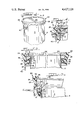
- FIG. 1 is a perspective view of my novel container and cap assembly
- FIG. 2 is an enlarged cross-sectional view taken substantially on line 2--2 of FIG. 1;
- FIG. 3 is a fragmentary sectional view such as FIG. 3 showing the parts in open position
- FIG. 4 is a cross-sectional view illustrating another modification of the invention.
- the can 2 comprises a can body wall 3 having the usual integral bottom (not shown).
- the top of the can is formed with a peripheral outturned flange 5 which is formed integral with a short downturned axial skirt wall 6, the lower edge of which is formed with an inturned ledge 8 which is connected to a rectangular shaped channel 10 closely embracing the can body wall 3.
- the channel has a pair of vertically space outer clamp strip webs 12, 13, top and bottom walls 14, 15, and an inner wall 16. The channel is tucked into the space between the skirt wall 6 and the body wall 3 and upper and lower clamping strip webs 12 and 13 define an outwardly open annular seal receiving gap or entryway 18 immediately below the ledge 8.
- a cap or closure 20 is fitted on the upper edge portion generally designated 22 of the can.
- the closure 20 comprises an annulus or collar portion 24 which is made from flexible plastic such as polyethylene.
- the annulus 24 comprises a skirt section 25 which is provided intermediate its top and bottom ends with an integral annular inwardly extending securing flange 26 normal to the axis of the can.
- the inner edge of the flange 26 is formed with a rectangular bead which fits complimentally within the channel 10 which initially has the lower clamping flange 13 extending horizontally as seen in dotted lines in FIG. 2 and is then swagged or crimped upwardly to close the gap and to firmly clamp flange 26 against the ledge 8 to obtain an air-tight seal.
- the skirt annulus 24 is made of thicker section at its upper portion 28 and has an internal groove 30.
- a flat metal disk 32 such as aluminum is fitted within the annulus and extends at its peripheral edge 34 into the groove 30 with a sealtight fit. If desired, the disk edge may be adhesively bonded to the groove surfaces.
- the securing flange has upper and lower axially aligned weakening notches or scores 35, 36 therein between its inner and outer edges such that the securing flange can be torn apart as seen in FIG. 3 by lifting on the tab 40 which extends downwardly from the annulus.
- the cap may be again fitted onto the upper end portion of the can whereupon the portion 26a of the securing flange is stretched over the skirt wall of the can until it snaps under the ledge.
- FIG. 4 is similar to FIGS. 1-3 and therefore like parts will be identified with the same reference numerals.
- the upper end portion of the can is formed with a curl or channel 50 of cylindrical cross-section and provides a downwardly facing gap 52.
- a complimentary bead 53 extends into the hollow 54 of the curl or channel and the securing and sealing flange 55 is clamped between the free edge 56 of the channel and the opposing terminus 57 of the channel formed from the can body wall to provide a sealtight connection.
- the securing flange has an annular weakening notch or score 58 on its underside 59 and that when the cover is lifted upwardly, the score will break and the cover may be removed. To reclose, the cover is fitted onto the upper end of the can body as in FIGS. 1-3 until the securing flange portion 55a snaps under the curl.
- the disk 32 is last inserted with groove 30 leaving an unobstructed opening 60 in the top wall 62 of the closure.
- a suitable tool may be applied against the top 64 and inside surface 65 of the curl to close the gap 52 to obtain a tight seal. Thereafter, the disk 32 is forced into the groove 30 by stretching the wall portion 62 and the disk sealed therein.
Abstract
Description
Claims (6)
Priority Applications (1)
| Application Number | Priority Date | Filing Date | Title |
|---|---|---|---|
| US06/434,156 US4427128A (en) | 1982-10-13 | 1982-10-13 | Can and closure therefor |
Applications Claiming Priority (1)
| Application Number | Priority Date | Filing Date | Title |
|---|---|---|---|
| US06/434,156 US4427128A (en) | 1982-10-13 | 1982-10-13 | Can and closure therefor |
Publications (1)
| Publication Number | Publication Date |
|---|---|
| US4427128A true US4427128A (en) | 1984-01-24 |
Family
ID=23723047
Family Applications (1)
| Application Number | Title | Priority Date | Filing Date |
|---|---|---|---|
| US06/434,156 Expired - Fee Related US4427128A (en) | 1982-10-13 | 1982-10-13 | Can and closure therefor |
Country Status (1)
| Country | Link |
|---|---|
| US (1) | US4427128A (en) |
Cited By (5)
| Publication number | Priority date | Publication date | Assignee | Title |
|---|---|---|---|---|
| US5385294A (en) * | 1989-02-22 | 1995-01-31 | Tetra Pak Holdings S.A. | Liquid package with aseptic properties and a method of producing such a package |
| WO1998042582A1 (en) * | 1997-03-25 | 1998-10-01 | Ball Corporation | Container with sealing member |
| WO1999035045A1 (en) | 1998-01-07 | 1999-07-15 | Dispensing Containers Corp | Resealable easy open closure and can |
| EP1695918A1 (en) * | 2005-02-24 | 2006-08-30 | Crown Packaging Technology, Inc | Easy open container and lid structure |
| US20070088300A1 (en) * | 2005-10-11 | 2007-04-19 | Bristol-Myers Squibb Company | Ostomy coupling |
-
1982
- 1982-10-13 US US06/434,156 patent/US4427128A/en not_active Expired - Fee Related
Cited By (12)
| Publication number | Priority date | Publication date | Assignee | Title |
|---|---|---|---|---|
| US5385294A (en) * | 1989-02-22 | 1995-01-31 | Tetra Pak Holdings S.A. | Liquid package with aseptic properties and a method of producing such a package |
| WO1998042582A1 (en) * | 1997-03-25 | 1998-10-01 | Ball Corporation | Container with sealing member |
| US5875914A (en) * | 1997-03-25 | 1999-03-02 | Ball Corporation | Container with integral endpiece and sealing member |
| US5950859A (en) * | 1997-03-25 | 1999-09-14 | Ball Corporation | Container with sealing member |
| US6102237A (en) * | 1997-03-25 | 2000-08-15 | Ball Corporation | Container with sealing member |
| WO1999035045A1 (en) | 1998-01-07 | 1999-07-15 | Dispensing Containers Corp | Resealable easy open closure and can |
| US6193094B1 (en) | 1998-01-07 | 2001-02-27 | George B. Diamond | Resealable easy open closure and can |
| EP1695918A1 (en) * | 2005-02-24 | 2006-08-30 | Crown Packaging Technology, Inc | Easy open container and lid structure |
| WO2006089819A1 (en) * | 2005-02-24 | 2006-08-31 | Crown Packaging Technology, Inc | Easy open container and lid structure |
| US20080185383A1 (en) * | 2005-02-24 | 2008-08-07 | Crown Packaging Technology, Inc. | Easy Open Container and Lid Structure |
| US20070088300A1 (en) * | 2005-10-11 | 2007-04-19 | Bristol-Myers Squibb Company | Ostomy coupling |
| US8100875B2 (en) * | 2005-10-11 | 2012-01-24 | Convatec Technologies Inc. | Ostomy coupling |
Similar Documents
| Publication | Publication Date | Title |
|---|---|---|
| CA2598855C (en) | Easy open container and lid structure | |
| US4385708A (en) | Tamper proof lid | |
| US4442971A (en) | Peelable, sealable closure arrangement | |
| US4281774A (en) | Tamper proof snap cap | |
| CA1312043C (en) | Composite retortable closure for plastic container | |
| US4171062A (en) | Container having closure fastening means | |
| US4930656A (en) | Container lid with a tear skirt | |
| FI89782B (en) | LOCK FOER TLLSLUTNING AV OEPPNINGEN I EN BURK | |
| US5758793A (en) | Reclosable top for can | |
| US3494500A (en) | Tear-type plastic closure with plastic pull ring | |
| MXPA04008629A (en) | Plastic lid for a can. | |
| US4407424A (en) | Plastic plug type closure for beverage containers | |
| CA1314501C (en) | Closure for containers | |
| US4066181A (en) | Container and closure assembly | |
| US4423822A (en) | Closure cap with thumb actuated removal assisting tab | |
| IE830350L (en) | Container closure cap | |
| CA2657872A1 (en) | Hinged lid for a food container with plastic lower ring | |
| US3994409A (en) | Easy opening closure | |
| US4244479A (en) | Tamperproof closure member | |
| US4427128A (en) | Can and closure therefor | |
| US4289252A (en) | Hermetically sealed container | |
| US4375969A (en) | Method for forming a composite container including a reversely curled body member | |
| US4299350A (en) | Composite container including a reversely curled body member | |
| JP4580064B2 (en) | Hinged cap | |
| US4456146A (en) | Composite closure having frangible opening means |
Legal Events
| Date | Code | Title | Description |
|---|---|---|---|
| AS | Assignment |
Owner name: CONTINENTAL GROUP, INC. THE; ONE HARBOR PLAZA, STA Free format text: ASSIGNMENT OF ASSIGNORS INTEREST.;ASSIGNOR:HEYN, WILLIAM M.;REEL/FRAME:004058/0949 Effective date: 19820927 |
|
| MAFP | Maintenance fee payment |
Free format text: PAYMENT OF MAINTENANCE FEE, 4TH YEAR, PL 97-247 (ORIGINAL EVENT CODE: M173); ENTITY STATUS OF PATENT OWNER: LARGE ENTITY Year of fee payment: 4 |
|
| FEPP | Fee payment procedure |
Free format text: PAYOR NUMBER ASSIGNED (ORIGINAL EVENT CODE: ASPN); ENTITY STATUS OF PATENT OWNER: LARGE ENTITY |
|
| FEPP | Fee payment procedure |
Free format text: MAINTENANCE FEE REMINDER MAILED (ORIGINAL EVENT CODE: REM.); ENTITY STATUS OF PATENT OWNER: LARGE ENTITY |
|
| LAPS | Lapse for failure to pay maintenance fees | ||
| FP | Lapsed due to failure to pay maintenance fee |
Effective date: 19920126 |
|
| STCH | Information on status: patent discontinuation |
Free format text: PATENT EXPIRED DUE TO NONPAYMENT OF MAINTENANCE FEES UNDER 37 CFR 1.362 |