US4440558A - Fabrication of optical preforms by axial chemical vapor deposition - Google Patents
Fabrication of optical preforms by axial chemical vapor deposition Download PDFInfo
- Publication number
- US4440558A US4440558A US06/387,983 US38798382A US4440558A US 4440558 A US4440558 A US 4440558A US 38798382 A US38798382 A US 38798382A US 4440558 A US4440558 A US 4440558A
- Authority
- US
- United States
- Prior art keywords
- heating zone
- plasma
- gaseous medium
- flow
- tubular element
- Prior art date
- Legal status (The legal status is an assumption and is not a legal conclusion. Google has not performed a legal analysis and makes no representation as to the accuracy of the status listed.)
- Expired - Lifetime
Links
Images
Classifications
-
- C—CHEMISTRY; METALLURGY
- C03—GLASS; MINERAL OR SLAG WOOL
- C03B—MANUFACTURE, SHAPING, OR SUPPLEMENTARY PROCESSES
- C03B37/00—Manufacture or treatment of flakes, fibres, or filaments from softened glass, minerals, or slags
- C03B37/01—Manufacture of glass fibres or filaments
- C03B37/012—Manufacture of preforms for drawing fibres or filaments
- C03B37/014—Manufacture of preforms for drawing fibres or filaments made entirely or partially by chemical means, e.g. vapour phase deposition of bulk porous glass either by outside vapour deposition [OVD], or by outside vapour phase oxidation [OVPO] or by vapour axial deposition [VAD]
- C03B37/01413—Reactant delivery systems
- C03B37/0142—Reactant deposition burners
- C03B37/01426—Plasma deposition burners or torches
-
- C—CHEMISTRY; METALLURGY
- C03—GLASS; MINERAL OR SLAG WOOL
- C03B—MANUFACTURE, SHAPING, OR SUPPLEMENTARY PROCESSES
- C03B2201/00—Type of glass produced
- C03B2201/06—Doped silica-based glasses
- C03B2201/08—Doped silica-based glasses doped with boron or fluorine or other refractive index decreasing dopant
-
- C—CHEMISTRY; METALLURGY
- C03—GLASS; MINERAL OR SLAG WOOL
- C03B—MANUFACTURE, SHAPING, OR SUPPLEMENTARY PROCESSES
- C03B2201/00—Type of glass produced
- C03B2201/06—Doped silica-based glasses
- C03B2201/20—Doped silica-based glasses doped with non-metals other than boron or fluorine
- C03B2201/28—Doped silica-based glasses doped with non-metals other than boron or fluorine doped with phosphorus
-
- C—CHEMISTRY; METALLURGY
- C03—GLASS; MINERAL OR SLAG WOOL
- C03B—MANUFACTURE, SHAPING, OR SUPPLEMENTARY PROCESSES
- C03B2201/00—Type of glass produced
- C03B2201/06—Doped silica-based glasses
- C03B2201/30—Doped silica-based glasses doped with metals, e.g. Ga, Sn, Sb, Pb or Bi
- C03B2201/31—Doped silica-based glasses doped with metals, e.g. Ga, Sn, Sb, Pb or Bi doped with germanium
-
- C—CHEMISTRY; METALLURGY
- C03—GLASS; MINERAL OR SLAG WOOL
- C03B—MANUFACTURE, SHAPING, OR SUPPLEMENTARY PROCESSES
- C03B2201/00—Type of glass produced
- C03B2201/06—Doped silica-based glasses
- C03B2201/30—Doped silica-based glasses doped with metals, e.g. Ga, Sn, Sb, Pb or Bi
- C03B2201/40—Doped silica-based glasses doped with metals, e.g. Ga, Sn, Sb, Pb or Bi doped with transition metals other than rare earth metals, e.g. Zr, Nb, Ta or Zn
- C03B2201/42—Doped silica-based glasses doped with metals, e.g. Ga, Sn, Sb, Pb or Bi doped with transition metals other than rare earth metals, e.g. Zr, Nb, Ta or Zn doped with titanium
-
- Y—GENERAL TAGGING OF NEW TECHNOLOGICAL DEVELOPMENTS; GENERAL TAGGING OF CROSS-SECTIONAL TECHNOLOGIES SPANNING OVER SEVERAL SECTIONS OF THE IPC; TECHNICAL SUBJECTS COVERED BY FORMER USPC CROSS-REFERENCE ART COLLECTIONS [XRACs] AND DIGESTS
- Y10—TECHNICAL SUBJECTS COVERED BY FORMER USPC
- Y10S—TECHNICAL SUBJECTS COVERED BY FORMER USPC CROSS-REFERENCE ART COLLECTIONS [XRACs] AND DIGESTS
- Y10S65/00—Glass manufacturing
- Y10S65/15—Nonoxygen containing chalogenides
- Y10S65/16—Optical filament or fiber treatment with fluorine or incorporating fluorine in final product
Definitions
- the present invention relates to an improved process for forming optical preforms for the production of optical fibers, this process being especially suited for making optical preforms which possess stepped index or graded index profiles. Such characteristics render it possible to draw optical fibers exhibiting reliable operating characteristics from such optical preforms.
- the prior art contemplates and describes techniques such as "soot" deposition or hydrolysis wherein a gas vapor mixture is hydrolyzed by a flame to form a glass precursor particulate.
- the particulate is then deposited on a rotating glass rod serving as a mandrel.
- the soot is deposited upon the mandrel in a perpendicular direction to provide successive layers of constant radius or to provide preforms with radial gradations by varying the dopant concentration in successive passes of the burner flame.
- the mandrel is then removed and the thus obtained cylindrical tubular preform is collapsed to a solid rod and then drawn into a fiber. This process is shown and discussed in U.S. Pat. No. 3,826,560 and U.S. Pat.
- U.S. Pat. No. 3,966,446 discusses a technique for providing an optical preform.
- the optical preform is fabricated by the axial deposition from a direction along the preform axis as opposed to radial deposition from a direction perpendicular to the preform axis.
- the technique does not require a mandrel and thus avoids the need for collapsing a cylindrical preform prior to drawing.
- the preforms thus provided in the above noted patent possess longitudinal gradations in the index of refraction and thus serve to enhance certain types of mode conversions.
- the fabrication techniques of all optical fiber preforms are broadly based on one fundamental principle, i.e. vapor phase deposition.
- the reported processes are chemical vapor deposition (CVD), modified chemical vapor deposition (MCVD), outside vapor phase oxidation (OVPO), inside vapor phase oxidation (IVPO), vapor phase axial deposition (VAD) and plasma-activated chemical vapor deposition (PCVD).
- CVD chemical vapor deposition
- MCVD modified chemical vapor deposition
- OVPO outside vapor phase oxidation
- IVPO inside vapor phase oxidation
- VAD vapor phase axial deposition
- PCVD plasma-activated chemical vapor deposition
- optical preforms of certain characteristic optical properties they are either too expensive, too time-consuming or too cumbersome to use commercially, or they are not suited for the production of optical preforms having differentiated optical characteristic properties, and especially for the production of radially graded or stepped index optical preforms.
- optical preforms especially such having radially stepped or graded refractive index, which method does not possess the disadvantages of the conventional methods used in the optical fiber manufacturing industry.
- Still another object of the present invention is to provide a method of producing optical preforms which renders it possible to avoid contamination of the material of the optical preform by impurities and to give the material of the preform the desired optical properties.
- a concomitant object of the present invention is to devise an apparatus which is especially suited for the performance of the method of the present invention.
- one feature of the present invention resides in a method of producing an optical preform, this method comprising the steps of forming a flow of a heated gaseous medium through and beyond a heating zone, including inducing a ring-shaped plasma in the heating zone for heating the gaseous medium to a predetermined temperature; introducing into the heating zone at least one reactant capable of undergoing a chemical conversion into an optical material soot at the predetermined temperature for the soot to be formed in the heating zone, and entrained in the flow of the gaseous medium for travel beyond the heating zone; and disposing a bait in the flow of the gaseous medium beyond the heating zone for depositing the entrained optical material soot on the bait and thus growing the optical preform.
- This method will be called plasma vapor phase axial deposition.
- a particular advantage of this method is that the temperature at the center of the ring-shaped plasma is much lower than that within the plasma itself so that the soot which is formed from the reactant has a much lower temperature than it would have had if the plasma were induced in this central region as well.
- the particles of the soot when they are deposited on the bait, they will be at a temperature lower than that at which any substantial contamination could occur. In many instances, this temperature will be so low that the soot particles will merely stick to one another without actually melting and fusing with each other on the bait. Under these circumstances, it is further advantages to sinter the optical preform of this consistency prior to the drawing of an optical fiber therefrom.
- the forming step includes aiming the flow of the gaseous medium substantially upwardly and when the disposing step includes positioning the bait above the heating zone.
- the gravitational forces and the entraining forces of the gaseous medium will act on the soot particles substantially in opposite directions, so that the soot particles will impact the bait or any particles previously deposited on the bait at a much lower speed than otherwise and also without any component of motion transversely of the bait or of the preform growing thereon, so that the distribution of the deposited particles will be as uniform and coaxial as possible.
- the forming step may advantageously include forcing an annual stream of a plasma-forming gaseous medium through the heating zone, and inducing the plasma in the annular stream. In this manner, it is assured that the plasma will acquire and maintain its desired annular configuration. Under these circumstances, it is especially advantageous when the forcing and admitting steps are performed coaxially and concurrently, that is, when the gaseous medium containing the reactant or reactants is introduced into the center of the heating zone separately from the annular stream of the plasma-forming gaseous medium but in the same flow direction as this annular stream.
- the method of the present invention is augmented by the step of confining the flow of the gaseous medium through the heating zone in an annular stream of a shielding gaseous medium flowing past the heating zone.
- the shielding gaseous medium will merge with the gaseous medium flowing through the heating zone in a manner which is not conducive of creating instabilities in the annular plasma.
- the inducing step is advantageously conducted by subjecting the gaseous medium present in the heating zone to an alternating electromagnetic field at a frequency of at least 20 MHz.
- an alternating electromagnetic field at a frequency of at least 20 MHz.
- the introducing step includes admitting halides of glass-forming materials into the heating zone, especially silicon halide or the mixture thereof with a germanium halide. These halides then constitute the reactants which are chemically converted in the heating zone and eventually form the soot particles which are entrained in the flow of the gaseous medium and eventually reach the bait or the growing preform to become deposited thereon.
- germanium halide is added to silicon halide, the resulting silica soot deposited on the bait will be doped with germania in a concentration which varies in the radial direction of the preform.
- a particular advantage of the method of the present invention is that the resulting optical preform is not contaminated by hydroxyl groups. Other dopants may also be added.
- the present invention also relates to an apparatus for producing an optical preform, this apparatus comprising means for forming a flow of a gaseous medium through and beyond a heating zone, including means for inducing a ring-shaped plasma in the heating zone, including heating the gaseous medium to a predetermined temperature; means for introducing into the heating zone at least one reactant capable of undergoing a chemical conversion into an optical material soot at the predetermined temperature for the soot to be formed in the heating zone and entrained in the form of soot in the gaseous medium for travel beyond the heating zone; and means for positioning a bait in the flow of the gaseous medium beyond the heating zone for depositing the entrained optical material soot on the bait and thus growing the optical preform.
- the forming and introducing means include a plasma torch having at least a first elongated tubular element bounding a first flow passage and a second elongated tubular element coaxially surrounding the first tubular element and bounding a second flow passage therewith, the flow passages having downstream ends at and upstream ends remote from the heating zone, means for admitting a plasma-forming gaseous medium and a gaseous medium containing at least the one reactant into the upstream ends respectively of the second and of first flow passages for flow toward the heating zone, and means for subjecting the gaseous medium present in the heating zone to alternating electromagnetic field.
- the plasma torch has an upright orientation such that the gaseous media issue upwardly out of the respective flow passages, while the positioning means holds the bait above the torch.
- the plasma torch further includes a third tubular element coaxially surrounding the second tubular element and bounding a third flow passage therewith which has a downstream end at the heating zone and an upstream end remote from the heating zone, and means for admitting shielding gaseous medium into the upstream end of the third passage for flow therethrough to the downstream end and beyond the same past the heating zone.
- the shielding gaseous medium issuing from the third passage protects the ring-shaped plasma present in the heating zone from external influences.
- the third tubular element has an extension which extends beyond the downstream ends of the flow passages and spacedly surrounds the heating zone.
- the shielding gaseous medium will serve to cool the torch and especially the extension of the third tubular element.
- the extension advantageously has a tubular end portion merging with and having a diameter exceeding that of the remainder of the tubular element, this end portion being situated at the heating zone.
- the cooling gaseous medium will expand into the larger-diameter end portion of the extension, so that its flow speed will be reduced and the dwell time of any unit of volume of this cooling gaseous fluid in the heating zone will be correspondingly increased, and so will the amount of heat accepted and carried away by such a volume unit.
- the spacing of the enlarged end portion from the plasma is also increased by increasing the diameter of this end portion, the heating effect of the plasma on this end portion is correspondingly reduced.
- the second tubular element may have, in accordance with another facet of the present invention, an end portion at the downstream ends of the flow passages which merges with the remainder of the second tubular element and has a diameter exceeding that of such remainder.
- the flow-through cross-sectional area of the downstream end of the second passage is increased and the flow-through cross-sectional area of the third passage is reduced, so that the advancement speed of the plasma-forming gaseous medium into the heating zone is reduced and the speed at which the cooling or shielding gaseous medium is ejected from the downstream end of the third flow passage for flow past the heating zone is increased, resulting in an improved cooling.
- the admitting means includes at least one inlet port for each of the passages. Then, it is advantageous when the inlet port for the plasma-forming gaseous medium and/or the inlet port for the shielding gaseous medium is oriented substantially tangentially of the respective upstream end of the associated flow passage.
- the admitting means may advantageously include means for admitting argon, oxygen or a mixture of argon and oxygen into the upstream end of the second passage, and a gaseous medium containing at least one halide of a glass-forming material into the first passage.
- the apparatus of the present invention further advantageously includes at least one electrically conductive coil spacedly surrounding the heating zone, and means for passing an alternating current at a frequency of at least 20 MHz through the coil as the subjecting means.
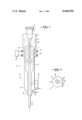
- FIG. 1 is a diagrammatic longitudinal sectional view through a plasma torch according to the present invention.
- FIG. 2 is a cross-sectional view taken on line II--II of FIG. 1.
- FIG. 1 illustrates a plasma torch 1 wherein a plasma 2 is produced in an inductively coupled oxygen-argon gas.
- This plasma 2 is generated by the use of a Lepel RF generator (Model No. T-20-3-DF1-TL42) at a frequency of 23 MHz.
- Lepel RF generator Model No. T-20-3-DF1-TL42
- the configuration of the plasma flame 2 is annular and is contained in the quartz glass torch 1.
- the oxidation reactions of the metal halide chemicals such as for instance silicon tetrachloride and germanium tetrachloride with oxygen result in production of very fine particles 3 of Ge-doped silica.
- the very fine particulate material 3 is entrained in the flow of a gaseous medium to be deposited on the rotating bait 4 so that a boule 5 is formed thereon.
- the bait 4 is gradually withdrawn from a deposition chamber 6.
- the rate of boule growth is equal to the rate at which the bait 4 is withdrawn. In this manner the deposition surface is maintained at a constant distance from the ring-shaped plasma 2.
- the torch 1 includes an inner tubular element 7, an intermediate tubular element 8 and an outer tubular element 9 which bound respective flow passages 10, 11 and 12.
- the inner tubular element 7 has an extension 13 through which the respective metal halide chemical enters the flow passage 10 in the axial direction, while the intermediate and outer tubular elements have respective inlet nipples or ports 14 and 15 which, as shown in FIG. 2, extend tangentially of the passages 11 and 12, and through which a plasma-sustaining gas, and a shielding gas, respectively, are introduced into the passages 11 and 12.
- the outer tubular element 9 at least partially bounds a heating zone 16 in which the annular plasma 2 is formed and causes the metal halide chemical or chemicals entering the heating zone 16 from the flow passage 10 to convert into corresponding metal oxides forming the particles or soot 3.
- the annular plasma 2 is generated and sustained by a high-frequency electromagnetic field emanating from a coil 17 which is supplied with electric current from an RF generator 18.
- the coil 17 surrounds a tubular extension 19 of the outer tubular element 9 which extends beyond the downstream end portions of the inner and intermediate tubular elements 7 and 8.
- the tubular extension 19 has an end portion 20 of a diameter exceeding that of the remainder of the extension 19 and of the tubular element 9, this end portion 20 radially merging into such a remainder.
- the enlarged diameter of the end portion 20 results in reduction of speed of the gaseous medium flowing through the chamber 6 and thus an improvement of the cooling action of such a gaseous medium.
- the second tubular element 8 is shown to have a similarly configurated downstream end portion 21. Because of the increased diameter of the end portion 21 relative to the remainder of the second tubular element 8, the speed of flow of the cooling gaseous medium around the end portion 21 is increased, and the speed of flow of the plasma-forming gaseous medium through the end portion 21 is reduced, so that beneficial flow conditions are obtained at the region of the ring-shaped plasma 2.
- the process parameters for the above-described experiment are as follows.
- the RF generator 18 had a power output equal to 13% of its maximum 20 kilowatts.
- the grid current was approximately 0.1 amps; plate voltage was approximately 6 kilovolts; plate current was approximately 0.5 amps and the frequency was 23 MHz.
- the plasma gases argon and oxygen had flow rates of: argon 0.5 to 1.0 liter/minute at a pressure of 20 p.s.i.; coolant gases: argon 12.0 to 17.0 liters/minute at a pressure of 20 p.s.i., and oxygen 5.0 to 10.0 liters/minute at a pressure of 25 p.s.i.
- the tubular elements 7, 8, 9 had the following dimensions: the first tubular element 7 had an outer diameter of 7 mm, the second tubular element 8 had an outer diameter of 11 mm, its end portion 21 had an outer diameter of 16 mm, the third tubular element 9 had an outer diameter of 20 mm, and its end portion 20 had an outer diameter of 29 mm.
- the wall thickness of the tubular element 7 was 2.5 mm, while the wall thickness of the tubular elements 8 and 9 was 1.5 mm.
- the inlet ports 14 and 15 had an outer diameter of 4.0 mm and a wall thickness of 1.0 mm.
- the plasma flame configuration of the plasma torch 1 can be tailored by taking advantage of the "skin-depth effect" in induction heating, the plasma generated at higher frequencies, for instance, greater than 20 MHz, has a ring-shaped doughnut shape.
- This plasma flame configuration can be further developed by optimizing the flow velocity of gases. Additionally, torch design and the applied volume flow rate will have an impact on the plasma flame configuration, but their impact will be lesser than that of the above-discussed variables.
- the above-described process permits deposition of the highly volatile germanium-doped silica glass using an Ar/O 2 plasma torch which provides a very clean high temperature heat source.
- a heat source has been found to be desirable in vapor phase axial deposition.
- a different inert gas may be mixed with the plasma-forming oxygen.
- dopants can be successfully incorporated in the SiO 2 soot by the novel invention described herein. These dopants are converted to the desirable form during their passage through the plasma and deposited in an axial manner to generate soot preform which can be sintered to finally draw optical fibers. These dopants can be varied over a wide range of elements e.g. Ti, P, B, F, Zr,Th and similar elements which can be used to vary the refractive index of SiO 2 for the fabrication of optical fiber.
- elements e.g. Ti, P, B, F, Zr,Th and similar elements which can be used to vary the refractive index of SiO 2 for the fabrication of optical fiber.
Abstract
Description
Claims (24)
Priority Applications (7)
| Application Number | Priority Date | Filing Date | Title |
|---|---|---|---|
| US06/387,983 US4440558A (en) | 1982-06-14 | 1982-06-14 | Fabrication of optical preforms by axial chemical vapor deposition |
| ZA833270A ZA833270B (en) | 1982-06-14 | 1983-05-06 | Forming optical preforms |
| NO832069A NO154667C (en) | 1982-06-14 | 1983-06-08 | PROCEDURE AND APPARATUS FOR MANUFACTURING OPTICAL PREFORM (SUBJECTS). |
| EP83105736A EP0096878B1 (en) | 1982-06-14 | 1983-06-11 | Fabrication of preforms for optical fibers by chemical vapor deposition using a plasma torch |
| DE8383105736T DE3367903D1 (en) | 1982-06-14 | 1983-06-11 | Fabrication of preforms for optical fibers by chemical vapor deposition using a plasma torch |
| AT83105736T ATE23848T1 (en) | 1982-06-14 | 1983-06-11 | MANUFACTURE OF OPTICAL FIBER PREFORMS BY CVD USING PLASMA TORCH. |
| JP58106598A JPS593036A (en) | 1982-06-14 | 1983-06-14 | Method and device for manufacturing optical preform by chemical gas phase axial method |
Applications Claiming Priority (1)
| Application Number | Priority Date | Filing Date | Title |
|---|---|---|---|
| US06/387,983 US4440558A (en) | 1982-06-14 | 1982-06-14 | Fabrication of optical preforms by axial chemical vapor deposition |
Publications (1)
| Publication Number | Publication Date |
|---|---|
| US4440558A true US4440558A (en) | 1984-04-03 |
Family
ID=23532129
Family Applications (1)
| Application Number | Title | Priority Date | Filing Date |
|---|---|---|---|
| US06/387,983 Expired - Lifetime US4440558A (en) | 1982-06-14 | 1982-06-14 | Fabrication of optical preforms by axial chemical vapor deposition |
Country Status (7)
| Country | Link |
|---|---|
| US (1) | US4440558A (en) |
| EP (1) | EP0096878B1 (en) |
| JP (1) | JPS593036A (en) |
| AT (1) | ATE23848T1 (en) |
| DE (1) | DE3367903D1 (en) |
| NO (1) | NO154667C (en) |
| ZA (1) | ZA833270B (en) |
Cited By (32)
| Publication number | Priority date | Publication date | Assignee | Title |
|---|---|---|---|---|
| US4554078A (en) * | 1984-05-21 | 1985-11-19 | At&T Technologies, Inc. | Methods of and apparatus for effluent disposal |
| US4597983A (en) * | 1983-07-20 | 1986-07-01 | Licentia Patent-Verwaltungs-Gmbh | Method for producing a directed aerosol stream |
| US4610892A (en) * | 1984-09-21 | 1986-09-09 | Licentia Patent-Verwaltungs-Gmbh | Method for producing a directed aerosol stream |
| US4650693A (en) * | 1984-07-25 | 1987-03-17 | Licentia Patent-Verwaltungs-Gmbh | Method for producing an aerosol stream |
| US4761170A (en) * | 1985-06-20 | 1988-08-02 | Polaroid Corporation | Method for employing plasma in dehydration and consolidation of preforms |
| US4810674A (en) * | 1987-02-24 | 1989-03-07 | Hoechst Celanese Corp. | Porous glass monoliths |
| US5665424A (en) * | 1994-03-11 | 1997-09-09 | Sherman; Dan | Method for making glass articles having a permanent protective coating |
| US5723172A (en) * | 1994-03-11 | 1998-03-03 | Dan Sherman | Method for forming a protective coating on glass |
| GB2346683A (en) * | 1999-02-05 | 2000-08-16 | Univ Glasgow | Flame hydrolysis deposition burner |
| US20020148560A1 (en) * | 2001-01-30 | 2002-10-17 | Carr Jeffrey W. | Apparatus and method for atmospheric pressure reactive atom plasma processing for shaping of damage free surfaces |
| US20020157421A1 (en) * | 2001-04-27 | 2002-10-31 | Ackerman Bradford G. | Method for producing titania-doped fused silica glass |
| US20020185331A1 (en) * | 2001-06-12 | 2002-12-12 | Deslauriers Richard J. | Tunable stethoscope head assembly |
| US20030016927A1 (en) * | 2001-07-17 | 2003-01-23 | Intelcore Technologies | Optical fiber with a radially varying index of refraction and related methods |
| US20030182971A1 (en) * | 1999-07-01 | 2003-10-02 | Alcatel | Plasma torch, method of fabricating an optical fiber preform and preform fabrication system using the method |
| US20040187525A1 (en) * | 2003-03-31 | 2004-09-30 | Coffey Calvin T. | Method and apparatus for making soot |
| US20050000656A1 (en) * | 2001-01-30 | 2005-01-06 | Rapt Industries, Inc. | Apparatus for atmospheric pressure reactive atom plasma processing for surface modification |
| US20050022561A1 (en) * | 2003-08-01 | 2005-02-03 | Guskov Michael I. | Ring plasma jet method and apparatus for making an optical fiber preform |
| US20060179893A1 (en) * | 2002-01-03 | 2006-08-17 | Draka Comteq B.V. | Device for overcladding preforms for optical fibers |
| US20060196230A1 (en) * | 2005-03-07 | 2006-09-07 | Samsung Electronics Co., Ltd | Plasma apparatus and apparatus for fabricating optical fiber preform by using the same |
| WO2007079127A2 (en) * | 2005-12-29 | 2007-07-12 | Silica Tech, Llc | Plasma torch for making synthetic silica |
| US20070163299A1 (en) * | 2005-12-23 | 2007-07-19 | Draka Comteq B.V. | Method and apparatus for manufacturing low oh overcladding |
| US20070169698A1 (en) * | 2003-08-01 | 2007-07-26 | Guskov Mikhail I | Ring plasma jet method and apparatus for making an optical fiber preform |
| US20080029485A1 (en) * | 2003-08-14 | 2008-02-07 | Rapt Industries, Inc. | Systems and Methods for Precision Plasma Processing |
| US20080035612A1 (en) * | 2003-08-14 | 2008-02-14 | Rapt Industries, Inc. | Systems and Methods Utilizing an Aperture with a Reactive Atom Plasma Torch |
| US20080099441A1 (en) * | 2001-11-07 | 2008-05-01 | Rapt Industries, Inc. | Apparatus and method for reactive atom plasma processing for material deposition |
| US20100167906A1 (en) * | 2008-12-29 | 2010-07-01 | Lars Ortmann | Process of making a dense synthetic silica glass, a muffle furnace for performing the process, and silica glass obtained from said process |
| US20100189926A1 (en) * | 2006-04-14 | 2010-07-29 | Deluca Charles | Plasma deposition apparatus and method for making high purity silicon |
| US20110162413A1 (en) * | 2008-09-09 | 2011-07-07 | Shin-Etsu Chemical Co., Ltd. | Method of manufacturing optical fiber base material |
| US20120247151A1 (en) * | 2011-03-31 | 2012-10-04 | Kelly Allen L | Apparatus for producing a vitreous inner layer on a fused silica body, and method of operating same |
| CN102781857A (en) * | 2010-03-02 | 2012-11-14 | 贺利氏石英英国有限公司 | Manufacture of synthetic silica glass |
| US9079792B2 (en) | 2011-03-31 | 2015-07-14 | Raytheon Company | Fused silica body with vitreous silica inner layer and method for making the same |
| CN105502897A (en) * | 2016-01-12 | 2016-04-20 | 中国建筑材料科学研究总院 | Preparing method for ultra-pure quartz glass |
Families Citing this family (4)
| Publication number | Priority date | Publication date | Assignee | Title |
|---|---|---|---|---|
| GB2162168B (en) * | 1984-07-25 | 1988-06-29 | Stc Plc | Optical fibre manufacture |
| JPH0741637Y2 (en) * | 1987-05-18 | 1995-09-27 | 日産自動車株式会社 | Garnish molding terminal processing structure |
| FR2714371B1 (en) * | 1993-12-24 | 1996-02-16 | Cabloptic Sa | Method for recharging an optical fiber preform, device for implementing this method and optical fiber by this method. |
| DE10054270B4 (en) * | 2000-11-02 | 2006-02-16 | Schott Ag | Process for producing photomask substrates |
Citations (12)
| Publication number | Priority date | Publication date | Assignee | Title |
|---|---|---|---|---|
| US30883A (en) * | 1860-12-11 | Improvement in corn-planters | ||
| US3957474A (en) * | 1974-04-24 | 1976-05-18 | Nippon Telegraph And Telephone Public Corporation | Method for manufacturing an optical fibre |
| US3966446A (en) * | 1975-10-23 | 1976-06-29 | Bell Telephone Laboratories, Incorporated | Axial fabrication of optical fibers |
| US4017288A (en) * | 1975-12-15 | 1977-04-12 | Bell Telephone Laboratories, Incorporated | Method for making optical fibers with helical gradations in composition |
| US4062665A (en) * | 1976-04-06 | 1977-12-13 | Nippon Telegraph And Telephone Public Corporation | Continuous optical fiber preform fabrication method |
| US4135901A (en) * | 1974-12-18 | 1979-01-23 | Sumitomo Electric Industries, Ltd. | Method of manufacturing glass for optical waveguide |
| JPS5459155A (en) * | 1977-10-19 | 1979-05-12 | Hitachi Ltd | Production of optical fibers |
| JPS54151625A (en) * | 1978-05-17 | 1979-11-29 | Nippon Telegr & Teleph Corp <Ntt> | Torch for synthesizing glass fine particles |
| US4224046A (en) * | 1977-08-11 | 1980-09-23 | Nippon Telegraph And Telephone Public Corporation | Method for manufacturing an optical fiber preform |
| US4225330A (en) * | 1977-07-27 | 1980-09-30 | Sumitomo Electric Industries, Ltd. | Process for producing glass member |
| US4230472A (en) * | 1979-02-22 | 1980-10-28 | Corning Glass Works | Method of forming a substantially continuous optical waveguide |
| US4242118A (en) * | 1979-04-27 | 1980-12-30 | International Standard Electric Corporation | Optical fiber manufacture |
Family Cites Families (2)
| Publication number | Priority date | Publication date | Assignee | Title |
|---|---|---|---|---|
| CH620181A5 (en) * | 1975-08-16 | 1980-11-14 | Heraeus Schott Quarzschmelze | Process for the preparation of synthetic quartz glass, apparatus to carry out the process, and the use of the synthetic quartz glass |
| FR2351064A1 (en) * | 1976-05-12 | 1977-12-09 | France Etat | PROCESS AND EQUIPMENT FOR PREFORMING PREFORMS FOR OPTICAL FIBERS |
-
1982
- 1982-06-14 US US06/387,983 patent/US4440558A/en not_active Expired - Lifetime
-
1983
- 1983-05-06 ZA ZA833270A patent/ZA833270B/en unknown
- 1983-06-08 NO NO832069A patent/NO154667C/en unknown
- 1983-06-11 AT AT83105736T patent/ATE23848T1/en not_active IP Right Cessation
- 1983-06-11 DE DE8383105736T patent/DE3367903D1/en not_active Expired
- 1983-06-11 EP EP83105736A patent/EP0096878B1/en not_active Expired
- 1983-06-14 JP JP58106598A patent/JPS593036A/en active Granted
Patent Citations (12)
| Publication number | Priority date | Publication date | Assignee | Title |
|---|---|---|---|---|
| US30883A (en) * | 1860-12-11 | Improvement in corn-planters | ||
| US3957474A (en) * | 1974-04-24 | 1976-05-18 | Nippon Telegraph And Telephone Public Corporation | Method for manufacturing an optical fibre |
| US4135901A (en) * | 1974-12-18 | 1979-01-23 | Sumitomo Electric Industries, Ltd. | Method of manufacturing glass for optical waveguide |
| US3966446A (en) * | 1975-10-23 | 1976-06-29 | Bell Telephone Laboratories, Incorporated | Axial fabrication of optical fibers |
| US4017288A (en) * | 1975-12-15 | 1977-04-12 | Bell Telephone Laboratories, Incorporated | Method for making optical fibers with helical gradations in composition |
| US4062665A (en) * | 1976-04-06 | 1977-12-13 | Nippon Telegraph And Telephone Public Corporation | Continuous optical fiber preform fabrication method |
| US4225330A (en) * | 1977-07-27 | 1980-09-30 | Sumitomo Electric Industries, Ltd. | Process for producing glass member |
| US4224046A (en) * | 1977-08-11 | 1980-09-23 | Nippon Telegraph And Telephone Public Corporation | Method for manufacturing an optical fiber preform |
| JPS5459155A (en) * | 1977-10-19 | 1979-05-12 | Hitachi Ltd | Production of optical fibers |
| JPS54151625A (en) * | 1978-05-17 | 1979-11-29 | Nippon Telegr & Teleph Corp <Ntt> | Torch for synthesizing glass fine particles |
| US4230472A (en) * | 1979-02-22 | 1980-10-28 | Corning Glass Works | Method of forming a substantially continuous optical waveguide |
| US4242118A (en) * | 1979-04-27 | 1980-12-30 | International Standard Electric Corporation | Optical fiber manufacture |
Cited By (60)
| Publication number | Priority date | Publication date | Assignee | Title |
|---|---|---|---|---|
| US4597983A (en) * | 1983-07-20 | 1986-07-01 | Licentia Patent-Verwaltungs-Gmbh | Method for producing a directed aerosol stream |
| US4554078A (en) * | 1984-05-21 | 1985-11-19 | At&T Technologies, Inc. | Methods of and apparatus for effluent disposal |
| US4650693A (en) * | 1984-07-25 | 1987-03-17 | Licentia Patent-Verwaltungs-Gmbh | Method for producing an aerosol stream |
| US4610892A (en) * | 1984-09-21 | 1986-09-09 | Licentia Patent-Verwaltungs-Gmbh | Method for producing a directed aerosol stream |
| US4761170A (en) * | 1985-06-20 | 1988-08-02 | Polaroid Corporation | Method for employing plasma in dehydration and consolidation of preforms |
| US4810674A (en) * | 1987-02-24 | 1989-03-07 | Hoechst Celanese Corp. | Porous glass monoliths |
| US5665424A (en) * | 1994-03-11 | 1997-09-09 | Sherman; Dan | Method for making glass articles having a permanent protective coating |
| US5723172A (en) * | 1994-03-11 | 1998-03-03 | Dan Sherman | Method for forming a protective coating on glass |
| GB2363637B (en) * | 1999-02-05 | 2003-09-24 | Univ Glasgow | Burner for fabricating aerosol doped waveguides |
| GB2346683A (en) * | 1999-02-05 | 2000-08-16 | Univ Glasgow | Flame hydrolysis deposition burner |
| US20060288739A1 (en) * | 1999-07-01 | 2006-12-28 | Draka Comteq B.V. | Plasma torch and preform fabrication system using the method |
| US7121120B2 (en) * | 1999-07-01 | 2006-10-17 | Alcatel | Method of glazing an optical fiber preform with a plasma of reduced power |
| US20030182971A1 (en) * | 1999-07-01 | 2003-10-02 | Alcatel | Plasma torch, method of fabricating an optical fiber preform and preform fabrication system using the method |
| US20020148560A1 (en) * | 2001-01-30 | 2002-10-17 | Carr Jeffrey W. | Apparatus and method for atmospheric pressure reactive atom plasma processing for shaping of damage free surfaces |
| US7510664B2 (en) * | 2001-01-30 | 2009-03-31 | Rapt Industries, Inc. | Apparatus and method for atmospheric pressure reactive atom plasma processing for shaping of damage free surfaces |
| US7591957B2 (en) | 2001-01-30 | 2009-09-22 | Rapt Industries, Inc. | Method for atmospheric pressure reactive atom plasma processing for surface modification |
| US20050000656A1 (en) * | 2001-01-30 | 2005-01-06 | Rapt Industries, Inc. | Apparatus for atmospheric pressure reactive atom plasma processing for surface modification |
| WO2002088036A1 (en) * | 2001-04-27 | 2002-11-07 | Corning Incorporated | Method for producing titania-doped fused silica extreme ultraviolet lithography substrates glass |
| US8047023B2 (en) | 2001-04-27 | 2011-11-01 | Corning Incorporated | Method for producing titania-doped fused silica glass |
| US20020157421A1 (en) * | 2001-04-27 | 2002-10-31 | Ackerman Bradford G. | Method for producing titania-doped fused silica glass |
| US20020185331A1 (en) * | 2001-06-12 | 2002-12-12 | Deslauriers Richard J. | Tunable stethoscope head assembly |
| US6807350B2 (en) | 2001-07-17 | 2004-10-19 | Verrillon, Inc. | Optical fiber with a radially varying index of refraction and related methods |
| US20030016927A1 (en) * | 2001-07-17 | 2003-01-23 | Intelcore Technologies | Optical fiber with a radially varying index of refraction and related methods |
| US7955513B2 (en) | 2001-11-07 | 2011-06-07 | Rapt Industries, Inc. | Apparatus and method for reactive atom plasma processing for material deposition |
| US20080099441A1 (en) * | 2001-11-07 | 2008-05-01 | Rapt Industries, Inc. | Apparatus and method for reactive atom plasma processing for material deposition |
| US20060179893A1 (en) * | 2002-01-03 | 2006-08-17 | Draka Comteq B.V. | Device for overcladding preforms for optical fibers |
| US7703305B2 (en) | 2002-01-03 | 2010-04-27 | Draka Comteq B.V. | Overcladding an optical fiber preform using an air-argon plasma torch |
| US20040187525A1 (en) * | 2003-03-31 | 2004-09-30 | Coffey Calvin T. | Method and apparatus for making soot |
| WO2004094323A1 (en) * | 2003-03-31 | 2004-11-04 | Corning Incorporated | A method and apparatus for making silica soot by vapor oxidation |
| US20070169698A1 (en) * | 2003-08-01 | 2007-07-26 | Guskov Mikhail I | Ring plasma jet method and apparatus for making an optical fiber preform |
| US7793612B2 (en) | 2003-08-01 | 2010-09-14 | Silica Tech, Llc | Ring plasma jet method and apparatus for making an optical fiber preform |
| US20110232332A1 (en) * | 2003-08-01 | 2011-09-29 | Guskov Mikhail I | Ring plasma jet method and apparatus for making an optical fiber preform |
| US8192807B2 (en) * | 2003-08-01 | 2012-06-05 | Silica Tech, Llc | Ring plasma jet method and apparatus for making an optical fiber preform |
| US20050022561A1 (en) * | 2003-08-01 | 2005-02-03 | Guskov Michael I. | Ring plasma jet method and apparatus for making an optical fiber preform |
| US20080035612A1 (en) * | 2003-08-14 | 2008-02-14 | Rapt Industries, Inc. | Systems and Methods Utilizing an Aperture with a Reactive Atom Plasma Torch |
| US20080029485A1 (en) * | 2003-08-14 | 2008-02-07 | Rapt Industries, Inc. | Systems and Methods for Precision Plasma Processing |
| US20060196230A1 (en) * | 2005-03-07 | 2006-09-07 | Samsung Electronics Co., Ltd | Plasma apparatus and apparatus for fabricating optical fiber preform by using the same |
| US20070163299A1 (en) * | 2005-12-23 | 2007-07-19 | Draka Comteq B.V. | Method and apparatus for manufacturing low oh overcladding |
| US8028545B2 (en) * | 2005-12-23 | 2011-10-04 | Draka Comteq B.V. | Method and apparatus for manufacturing low OH overcladding |
| WO2007079127A2 (en) * | 2005-12-29 | 2007-07-12 | Silica Tech, Llc | Plasma torch for making synthetic silica |
| WO2007079127A3 (en) * | 2005-12-29 | 2007-09-07 | Silica Tech Llc | Plasma torch for making synthetic silica |
| US7861557B2 (en) | 2005-12-29 | 2011-01-04 | Silica Tech, Llc | Plasma torch for making synthetic silica |
| US20070169516A1 (en) * | 2005-12-29 | 2007-07-26 | Guskov Mikhail I | Plasma torch for making synthetic silica |
| CN101389573B (en) * | 2005-12-29 | 2011-11-16 | 硅石技术责任有限公司 | Plasma torch for making synthetic silica |
| US20100189926A1 (en) * | 2006-04-14 | 2010-07-29 | Deluca Charles | Plasma deposition apparatus and method for making high purity silicon |
| WO2008140501A2 (en) * | 2006-12-26 | 2008-11-20 | Silica Tech Llc | Ring plasma jet method and apparatus for making an optical fiber preform |
| WO2008140501A3 (en) * | 2006-12-26 | 2009-04-16 | Silica Tech Llc | Ring plasma jet method and apparatus for making an optical fiber preform |
| US8820121B2 (en) * | 2008-09-09 | 2014-09-02 | Shin-Etsu Chemical Co., Ltd. | Method of manufacturing optical fiber base material |
| US20110162413A1 (en) * | 2008-09-09 | 2011-07-07 | Shin-Etsu Chemical Co., Ltd. | Method of manufacturing optical fiber base material |
| CN101863613A (en) * | 2008-12-29 | 2010-10-20 | 肖特股份有限公司 | Process of making a dense synthetic silica glass, a muffle furnace for performing the process, and silica glass obtained from said process |
| US20100167906A1 (en) * | 2008-12-29 | 2010-07-01 | Lars Ortmann | Process of making a dense synthetic silica glass, a muffle furnace for performing the process, and silica glass obtained from said process |
| CN102781857A (en) * | 2010-03-02 | 2012-11-14 | 贺利氏石英英国有限公司 | Manufacture of synthetic silica glass |
| US20130045854A1 (en) * | 2010-03-02 | 2013-02-21 | Heraeus Quartz Uk Limited | Manufacture of synthetic silica glass |
| US8959957B2 (en) * | 2010-03-02 | 2015-02-24 | Heraeus Quartz Uk Limited | Manufacture of synthetic silica glass |
| CN102781857B (en) * | 2010-03-02 | 2016-09-07 | 贺利氏石英英国有限公司 | The preparation of the silica glass of synthesis |
| US20120247151A1 (en) * | 2011-03-31 | 2012-10-04 | Kelly Allen L | Apparatus for producing a vitreous inner layer on a fused silica body, and method of operating same |
| US9079792B2 (en) | 2011-03-31 | 2015-07-14 | Raytheon Company | Fused silica body with vitreous silica inner layer and method for making the same |
| US9193620B2 (en) | 2011-03-31 | 2015-11-24 | Raytheon Company | Fused silica body with vitreous silica inner layer, and method for making same |
| US9221709B2 (en) * | 2011-03-31 | 2015-12-29 | Raytheon Company | Apparatus for producing a vitreous inner layer on a fused silica body, and method of operating same |
| CN105502897A (en) * | 2016-01-12 | 2016-04-20 | 中国建筑材料科学研究总院 | Preparing method for ultra-pure quartz glass |
Also Published As
| Publication number | Publication date |
|---|---|
| JPS593036A (en) | 1984-01-09 |
| ATE23848T1 (en) | 1986-12-15 |
| NO154667B (en) | 1986-08-18 |
| EP0096878A1 (en) | 1983-12-28 |
| EP0096878B1 (en) | 1986-11-26 |
| ZA833270B (en) | 1984-01-25 |
| DE3367903D1 (en) | 1987-01-15 |
| NO154667C (en) | 1986-11-26 |
| JPS6124339B2 (en) | 1986-06-10 |
| NO832069L (en) | 1983-12-15 |
Similar Documents
| Publication | Publication Date | Title |
|---|---|---|
| US4440558A (en) | Fabrication of optical preforms by axial chemical vapor deposition | |
| RU2217391C2 (en) | Method of forming tubular element for production of optical fiber by means of external plasma precipitation from vapor phase | |
| US4262035A (en) | Modified chemical vapor deposition of an optical fiber using an rf plasma | |
| US4345928A (en) | Fabrication method of single-mode optical fiber preforms | |
| CA2047187C (en) | Improved vitreous silica products | |
| US4331462A (en) | Optical fiber fabrication by a plasma generator | |
| US4135901A (en) | Method of manufacturing glass for optical waveguide | |
| US3980459A (en) | Method for manufacturing optical fibers having eccentric longitudinal index inhomogeneity | |
| US4235616A (en) | Optical waveguide manufacturing process and article | |
| US4334903A (en) | Optical fiber fabrication | |
| Izawa et al. | Materials and processes for fiber preform fabrication—Vapor-phase axial deposition | |
| GB2128982A (en) | Fabrication method of optical fiber preforms | |
| JP4375902B2 (en) | Manufacturing method of optical fiber preform | |
| US4608070A (en) | Process for manufacturing optical-fibre preforms at high deposition rate | |
| US4302230A (en) | High rate optical fiber fabrication process using thermophoretically enhanced particle deposition | |
| US4414008A (en) | Process for producing optical fiber preform | |
| JP4404767B2 (en) | Method and apparatus for producing preforms from synthetic quartz glass using plasma assisted deposition | |
| EP0072069B1 (en) | Method of producing preforms for drawing optical fibres and apparatus for the continuous production of optical fibres | |
| US20120285202A1 (en) | Method Of Fabricating Optical Fiber Using An Isothermal, Low Pressure Plasma Deposition Technique | |
| US4504299A (en) | Optical fiber fabrication method | |
| GB2068359A (en) | Manufacture of optical fibre preforms | |
| EP0112549B1 (en) | Improved sintering of optical fiber preforms | |
| Schultz | Vapor phase materials and processes for glass optical waveguides | |
| Sarkar | Fabrication techniques for high-quality optical fibers | |
| JPS6045133B2 (en) | Method for manufacturing base material for optical glass fiber |
Legal Events
| Date | Code | Title | Description |
|---|---|---|---|
| AS | Assignment |
Owner name: INTERNATIONAL TELEPHONE AND TELEGRAPH CORPORATION, Free format text: ASSIGNMENT OF ASSIGNORS INTEREST.;ASSIGNORS:NATH, DILIP K.;PUREZA, PABLO;OH, SHIN M.;REEL/FRAME:004007/0928 Effective date: 19820601 |
|
| STCF | Information on status: patent grant |
Free format text: PATENTED CASE |
|
| AS | Assignment |
Owner name: ITT CORPORATION Free format text: CHANGE OF NAME;ASSIGNOR:INTERNATIONAL TELEPHONE AND TELEGRAPH CORPORATION;REEL/FRAME:004389/0606 Effective date: 19831122 |
|
| AS | Assignment |
Owner name: U.S. HOLDING COMPANY, INC., C/O ALCATEL USA CORP., Free format text: ASSIGNMENT OF ASSIGNORS INTEREST. EFFECTIVE 3/11/87;ASSIGNOR:ITT CORPORATION;REEL/FRAME:004718/0039 Effective date: 19870311 |
|
| MAFP | Maintenance fee payment |
Free format text: PAYMENT OF MAINTENANCE FEE, 4TH YEAR, PL 96-517 (ORIGINAL EVENT CODE: M170); ENTITY STATUS OF PATENT OWNER: LARGE ENTITY Year of fee payment: 4 |
|
| AS | Assignment |
Owner name: ALCATEL USA, CORP. Free format text: CHANGE OF NAME;ASSIGNOR:U.S. HOLDING COMPANY, INC.;REEL/FRAME:004827/0276 Effective date: 19870910 Owner name: ALCATEL USA, CORP.,STATELESS Free format text: CHANGE OF NAME;ASSIGNOR:U.S. HOLDING COMPANY, INC.;REEL/FRAME:004827/0276 Effective date: 19870910 |
|
| AS | Assignment |
Owner name: ALCATEL NA CABLE SYSTEMS, INC. A CORP. OF DELAWA Free format text: ASSIGNMENT OF ASSIGNORS INTEREST.;ASSIGNOR:ALCATEL USA CORP. A CORP. OF DELAWARE;REEL/FRAME:005712/0033 Effective date: 19910520 |
|
| MAFP | Maintenance fee payment |
Free format text: PAYMENT OF MAINTENANCE FEE, 8TH YEAR, PL 96-517 (ORIGINAL EVENT CODE: M171); ENTITY STATUS OF PATENT OWNER: LARGE ENTITY Year of fee payment: 8 |
|
| FEPP | Fee payment procedure |
Free format text: PAYOR NUMBER ASSIGNED (ORIGINAL EVENT CODE: ASPN); ENTITY STATUS OF PATENT OWNER: LARGE ENTITY |
|
| MAFP | Maintenance fee payment |
Free format text: PAYMENT OF MAINTENANCE FEE, 12TH YEAR, LARGE ENTITY (ORIGINAL EVENT CODE: M185); ENTITY STATUS OF PATENT OWNER: LARGE ENTITY Year of fee payment: 12 |
|
| FEPP | Fee payment procedure |
Free format text: PAYOR NUMBER ASSIGNED (ORIGINAL EVENT CODE: ASPN); ENTITY STATUS OF PATENT OWNER: LARGE ENTITY Free format text: PAYER NUMBER DE-ASSIGNED (ORIGINAL EVENT CODE: RMPN); ENTITY STATUS OF PATENT OWNER: LARGE ENTITY |