US4450756A - Fume exhauster device - Google Patents
Fume exhauster device Download PDFInfo
- Publication number
- US4450756A US4450756A US06/336,934 US33693482A US4450756A US 4450756 A US4450756 A US 4450756A US 33693482 A US33693482 A US 33693482A US 4450756 A US4450756 A US 4450756A
- Authority
- US
- United States
- Prior art keywords
- air current
- exit opening
- axially
- fume exhauster
- impeller
- Prior art date
- Legal status (The legal status is an assumption and is not a legal conclusion. Google has not performed a legal analysis and makes no representation as to the accuracy of the status listed.)
- Expired - Fee Related
Links
Images


Classifications
-
- F—MECHANICAL ENGINEERING; LIGHTING; HEATING; WEAPONS; BLASTING
- F24—HEATING; RANGES; VENTILATING
- F24C—DOMESTIC STOVES OR RANGES ; DETAILS OF DOMESTIC STOVES OR RANGES, OF GENERAL APPLICATION
- F24C15/00—Details
- F24C15/20—Removing cooking fumes
- F24C15/2028—Removing cooking fumes using an air curtain
-
- F—MECHANICAL ENGINEERING; LIGHTING; HEATING; WEAPONS; BLASTING
- F24—HEATING; RANGES; VENTILATING
- F24F—AIR-CONDITIONING; AIR-HUMIDIFICATION; VENTILATION; USE OF AIR CURRENTS FOR SCREENING
- F24F9/00—Use of air currents for screening, e.g. air curtains
-
- F—MECHANICAL ENGINEERING; LIGHTING; HEATING; WEAPONS; BLASTING
- F24—HEATING; RANGES; VENTILATING
- F24F—AIR-CONDITIONING; AIR-HUMIDIFICATION; VENTILATION; USE OF AIR CURRENTS FOR SCREENING
- F24F13/00—Details common to, or for air-conditioning, air-humidification, ventilation or use of air currents for screening
- F24F13/02—Ducting arrangements
- F24F13/06—Outlets for directing or distributing air into rooms or spaces, e.g. ceiling air diffuser
- F24F2013/0616—Outlets that have intake openings
-
- Y—GENERAL TAGGING OF NEW TECHNOLOGICAL DEVELOPMENTS; GENERAL TAGGING OF CROSS-SECTIONAL TECHNOLOGIES SPANNING OVER SEVERAL SECTIONS OF THE IPC; TECHNICAL SUBJECTS COVERED BY FORMER USPC CROSS-REFERENCE ART COLLECTIONS [XRACs] AND DIGESTS
- Y10—TECHNICAL SUBJECTS COVERED BY FORMER USPC
- Y10S—TECHNICAL SUBJECTS COVERED BY FORMER USPC CROSS-REFERENCE ART COLLECTIONS [XRACs] AND DIGESTS
- Y10S55/00—Gas separation
- Y10S55/36—Kitchen hoods
Definitions
- This invention relates to a fume exhauster device comprising first means for generating a first air current directed substantially axially towards said first means, and second means for generating a second air current concentrically surrounding said first air current and flowing in circumferential and axial directions away from said second means.
- a fume exhauster device of the above captioned type for employ for instance with a kitchen stove for exhausting fumes and other volatile reaction products released during cooking and frying
- said known device comprising a cylindrical swirl duct opening downwards in the direction of the fume source, and one or several jets located about the upper portion of said swirl duct and opening tangentially into the interior thereof at a downward inclined angle toward said fume source.
- the swirl duct and the jets which in the known fume exhauster device act as said second means, serve to generate said second air current flowing downward in axial direction towards the fume source as well as in circumferential direction and surrounding a first air current in the form of an upward directed axial suction current.
- the upward directed first air current is formed, or generated, respectively, by the swirl duct and an exhaust duct connected to the upper end portion thereof and forming said first means therewith.
- the known fume exhauster device will, by means of said swirl duct and said jets, generate said second air current in the form of a curtain concentrically surrounding said first air current, the formation of this current is not achieved in practice, since the axial length of such curtain is determined by the angle of inclination of the jets within the swirl duct and depends of a corresponding lengthening of the swirl duct in axial direction.
- the jets will generate individual helical streams separated by open interstices through which the surrounding air may penetrate, deteriorating the vacuum required within the curtain for generating the first air current.
- An increase of the velocity of the air current generated by the jets does not either remedy this defect, since the inner and outer flow vortices within the swirl duct will move closer together with increasing flo velocities, whereby the inner current may be entrained by the outer current, so that the fume-laden air may again be ejected downward.
- the formation of the second air current as a closed curtain is thus only possible with a swirl duct of sufficient length, the diameter of this curtain being even then only a fraction of the opening diameter of the swirl duct.
- said second means comprises a substanially annular exit opening defined at least along its outer periphery by a peripheral surface extending in axial direction for forming said second air current into a cylindric shroud the outer diameter of which is substantially equal to the outer diameter of the exit opening.
- the second air current exits from an annular exit opening.
- At least the outer peripheral surface defining said exit opening extends over a determined length in the axial direction of the second air current in order to impart the form of a homogenous cylinder shroud to the second air current exiting from the exit opening and having flow components extending in the axial and circumferential directions.
- the inner boundary of the exit opening may also be formed by a circumferential surface extending in axial direction of the second air current, the relative lengths of the outer and inner boundary surfaces in this case determining an eventual divergence or convergence of the cylinder shroud.
- the resulting cylinder shroud will have a substantially constant diameter or may even be slightly convergent, while a greater length in the flow direction of the second air current of the inner boundary surface will result in a divergent cylinder shroud.
- the axial and circumferential flow components of the second air current may be created in various manners, such as by employing an axial impeller, a radial impeller rotor in combination with suitable flow guide means or even stationary baffles impinged on by a substantially axially directed air current.
- FIG. 1a shows a first embodiment having an axial impeller integral with a housing forming a flow guide means
- FIG. 1b shows a second embodiment having an axial impeller and a stationary housing forming a flow guide means
- FIG. 1c shows a third embodiment with an axial impeller having two impeller vane rings, and a stationary housing acting as a flow guide,
- FIG. 2a shows a fourth embodiment having a radial impeller rotor and a corotating disc contributing to guiding the air current
- FIG. 2b shows a fifth embodiment having a radial impeller rotor and a corotating disc contributing to guiding the air current
- FIG. 2c shows a sixth embodiment having a radial impeller rotor and a stationary disc contributing to guiding the air current
- FIG. 2d shows a seventh embodiment having a radial impeller rotor and a stationary disc contributing to guiding the air current and formed with a inner peripheral surface extending beyond the outer peripheral surface of the exit opening in the flow direction of the second air current,
- FIG. 3 shows an eighth embodiment having an axial impeller with two impeller vane rings, an air current induction duct, and an air current exhaust duct,
- FIG. 4 shows an embodiment similar to that of FIG. 3 including in addition a suction blower in the air current exhaust duct,
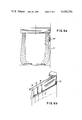
- FIG. 5a and 5b show a first arrangement of a baffle for eliminating the effect of a wall interfering with the cylinder shroud-shaped second air current
- FIG. 6a and 6b show a second arrangement of a baffle for eliminating the effect of a wall interfering with the cylinder shroud-shaped second air current
- FIG. 7a shows a ninth embodiment with stationary flow guide baffles disposed in the exit opening
- FIG. 7b shows a tenth embodiment having a radial impeller rotor the outer peripheral surface of which forms the inner boundary surface of the exit opening.
- the first and second means are formed by a housing 1 integrally connected to an axial impeller 2 having a first ring of impeller vanes 3 extending in substantially radial direction in an exit opening 7, said opening being defined by an outer and an inner peripheral surface 71 and 72, respectively.
- outer peripheral surface 71 extends beyond inner peripheral surface 72, whereby the second air current is formed into a cylinder shroud of substantially constant diameter or into a slightly converging cylinder shroud.
- the center portion of axial impeller 2 has a through-opening and is provided with a filter 4 releasably affixed to the drive shaft of an impeller motor 5 by means of a single center bolt 6.
- the first air current enters housing 1 in axial direction through filter 4, is deflected within the housing and is then accelerated by the impeller vanes 3 in exit opening 7 to exit downward therefrom in axial direction as the second air current.
- the second air current Due to the rotation of axial impeller 2, the second air current has a downward-directed axial flow component as well as a circumferential flow component.
- the intake side of axial impeller 2 thus forms the first means, while the second means is generally formed by the outlet side of impeller 2 in combination with exit opening 7.
- Impeller motor 5 is stationary, while housing 1 is integral with impeller 2 for rotation therewith and with the drive shaft of motor 5.
- the second embodiment of the fume exhauster device shown in FIG. 1b differs from the embodiment shown in FIG. 1a mainly by the housing 1 being stationary, so that the axial impeller rotates relative thereto. While the outer peripheral surface 71 defining the exit opening 7 is again formed by the inner peripheral surface of housing 1, the inner peripheral surface 72 of exit opening 7 is formed by the inner peripheral surface of the impeller vane ring 3. Filter 4 is formed here as a filter ring concentrically surrounding impeller motor 5. Operation of this second embodiment is substantially identical with that of the first embodiment.
- axial impeller 2 is provided with two impeller vane rings 3 and 8, the vanes of which are oriented at opposite attitudes to one another.
- the first ring of vanes 3 of axial impeller 2 again generates the second air current, creating an axially downwardly and a circumferentially directed flow component therein.
- the second ring of impeller vanes 8 on the other hand generates the first air current having only a substantially axial upwardly directed flow component.
- Housing 1 is again stationary, and its inner peripheral surface forms the outer boundary surface 71 of exit opening 7.
- the inner boundary surface 72 of exit opening 7 is again formed by the inner peripheral surface of first impeller vane ring 3.
- the third embodiment additionally includes a protective grid 9 formed of concentric rings for minimizing eddy-current losses.
- the annular filter 4 is located downstream of the second impeller vanes 8 and rotates in unison with axial impeller 2.
- the axial impeller employed in the preceding embodiments is replaced by a radial impeller rotor 10 acting as said first means for generating the axially upwardly directed first air current at its intake side.
- impeller 10 At its downstream side, impeller 10 generates a substantially radial and circumferential air current, which by means of a flow guide formed by housing 1 is deflected downwards in the direction of exit opening 7, exiting therefrom as the second air current again having axially downwardly and circumferentially directed flow components.
- the air current is additionally guided by a disc-shaped plate 11 rigidly attached to radial impeller rotor 10 for rotation therewith.
- the center portion of plate 11 has a through-opening for ingress of the first air current and for receiving filter 4 and an additional charcoal filter disc 41.
- Filters 4 and 41 are again releasably fastened by means of a single center bolt 6, so that they may be readily replaced.
- the outer boundary surface 71 of exit opening 7 is again formed by the inner peripheral surface of stationary housing 1, while the inner boundary 42 of exit opening 7 is formed by the edge of disc-shaped plate 11.
- FIG. 2b shows an embodiment of the fume exhauster device similar to the one shown in FIG. 2a and also comprising a radial impeller rotor 10.
- the device shown in FIG. 2b includes an additional filter 42 rotating in unison with the disc-shaped plate 11 and the impeller 10 and being in the form of a filter ring for passage therethrough of the air current accelerated by impeller 10 in radial direction. Otherwise the operation of this embodiment substantially corresponds to that of the embodiment shown in FIG. 2a.
- the sixth embodiment shown in FIG. 2c likewise comprises a radial impeller rotor 10.
- the disc-shaped plate 11 is stationary and connected to stationary housing 1 by means of bolts 12.
- Plate 11 again has a center opening for receiving filter 4 and an additional charcoal filter 41 connected to impeller 10 for rotation in unison therewith.
- Filters 4, 41 are again releasably attached to impeller 10 by means of a single center bolt 6.
- the remainder of this embodiment as well as its operation again correspond to those of the preceding embodiments and need therefore not be described in detail.
- the seventh embodiment of the fume exhauster device shown in FIG. 2d corresponds to the one shown in FIG. 2c, with the difference, however, that the stationary disc-shaped plate 11 has a cylindrical peripheral surface extending downward in the axial direction of the second air current and forming the inner boundary surface 72 of exit opening 7.
- the inner boundary surface 72 of exit opening 7 in this embodiment is of greater length in the direction of the second air current than the outer boundary surface 71, whereby to achieve a divergence of the homogenous cylinder shroud shape of the second air current.
- an axial impeller 2 having a first ring of impeller vanes 3 and a second ring of impeller vanes 8, so that this embodiment corresponds to the one shown in FIG. 1c.
- Axial impeller 2 additionally includes further impeller vanes 13 located adjacent impeller motor 5 for the cooling thereof.
- the first air current generated by means of the second ring of impeller vanes 8 is exhausted to the atmosphere via an exhaust duct 14, while the second air current generated by the first ring of impeller vanes 3 is formed of fresh air or interior air supplied via an air supply duct 15.
- the outer boundary surface 71 of exit opening 7 in this embodiment is formed by the outer peripheral wall of axial impeller 2, while the inner boundary surface, which in the shown embodiment is shorter in the direction of the second air current, is formed by the inner wall of the first ring of impeller vanes 3 of axial impeller 2. Also in this embodiment, the first ring of impeller vanes 3 generates an axially and circumferentially downwardly directed second air current forming a homogenous cylinder shroud the diameter of which is substantially constant or may even steadily decrease so as to form a convergent cylinder shroud shape.
- FIG. 4 represents an embodiment generally similar to the one shown in FIG. 3, wherein, however, the axial impeller 2 comprises only a first ring of impeller vanes 3, the first axially upwardly directed air current being generated by a separate blower 19 disposed in air exhaust duct 14 and passing through openings provided in axial impeller 2 for this purpose.
- outer boundary surface 71 of exit opening 7 is again longer in the direction of the second air current than inner boundary surface 72.
- FIGS. 5a and 5b Diagrammatically shown in FIGS. 5a and 5b is the arrangement of a baffles 16 provided for compensating the effect of a wall 17 interfering with the cylinder shroud shape of the second air current by cutting off a circle segment as shown diagrammatically at 18 in FIG. 5b. Without baffle 16, this disturbance would cause the cylinder shroud shape to expand or even rupture on separation from wall 17, whereby the homogeneity of the cylinder shroud shape of the second air current would be abolished. In the shown embodiment, however, the circumferential flow component of the second air current separating from wall 17 now impinges on baffle 16 extending in the axial direction along the cylinder shroud of the second air current, and is thereby deflected back to its original circumferential direction. This provision is of particular importance for a fume exhauster device employed in combination with a kitchen stove, since a stove of this kind is usually located adjacent a vertical wall, such as wall 17, likely to interfere with the cylinder shroud shape of the
- FIGS. 6a and 6b show another arrangement for eliminating the disturbing effect of a wall 17.
- the embodiment shown provides a curved baffle 20 gradually sloping away from wall 17 in the direction of the second air current for slightly deflecting the cylinder shroud periphery at a downward inclined angle, so that the homogenous cylinder shroud shape of the second air current is not disturbed or impaired by wall 17.
- curved baffle 20 may be provided with additional baffles 16', the effect of which is similar to that of baffle 16 shown in FIGS. 5a and 5b.
- a plurality of such baffles 16' may be provided, in which case they are preferably graduated as to size for achieving optimum compensation of the disturbing effect of wall 17.
- a further embodiment of the fume exhauster device shown in FIG. 7a employs neither an axial impeller nor a radial impeller rotor, instead of which it is provided with stationary deflector members 31 corresponding to the impeller vanes 3 of axial impeller 2 and located in exit opening 7.
- Deflector members 31 are disposed substantially radially and are formed and oriented such as to convert an air current impinging thereon from above into a second air current having a downwardly directed axial as well as a circumferential flow component. Also in this case, the outer boundary surface 71 of exit opening 7 is longer in the direction of the second air current than it inner boundary surface 72.
- the first air current is generated or assisted by a blower 19 in air exhaust duct 14, while the second air current is generated by means of a separate blower 20 disposed in air intake duct 15 in cooperation with the above mentioned stationary deflector members 31.
- a further embodiment of the fume exhauster device shown in FIG. 7b employs a radial impeller rotor 10 provided at its outer periphery with a filter material 43 arranged in such a manner that the axially upwardly aspirated air of the first air current is given a radial and a circumferential component, whereby this air after deflection by the stationary housing exits from exit opening 7 as the second air current having a downwardly directed axial as well as a circumferential flow component.
- outer boundary surface 71 is again formed by the inner peripheral surface of housing 1, while inner boundary surface 72 of exit opening 7 is formed by the outer peripheral surface of the radial impeller rotor.
- annular exit opening 7 and the particular configuration of its outer and inner boundary surfaces 71 and 72, respectively, permit the formation of the second air current into a homogenous cylinder shroud shape of considerable length without requiring, as in prior art, a swirl duct of considerable dimensions.
- An important characteristic in connection with the particular configuration of the exit opening is the provision that the second air current is imparted a downwardly directed axial as well as a circumferential flow component, as per se known from prior art.
- the outer boundary surface may be aerodynamically shaped as a deflector surface having for instance an airfoil profile in cross section for influencing the shape of the cylinder shroud air current, e.g. to make it convergent or divergent.
Abstract
A fume exhauster device comprising first means for generating a first air current directed substantially axially toward the first means, and second means for generating a second air current concentrically surrounding the first air current and flowing in circumferential and axial directions away from the second means, the second means comprising a substantially annular exit opening defined at least along its outer periphery by a peripheral surface extending in axial direction for forming the second air current into a cylinder shroud the outer diameter of which is substantially equal to the outer diameter of the exit opening.
Description
This is a continuation of application Ser. No. 70,055 filed Aug. 27, 1979 now abandoned.
This invention relates to a fume exhauster device comprising first means for generating a first air current directed substantially axially towards said first means, and second means for generating a second air current concentrically surrounding said first air current and flowing in circumferential and axial directions away from said second means.
Known from DE-PS No. 1,289,974 is a fume exhauster device of the above captioned type for employ for instance with a kitchen stove for exhausting fumes and other volatile reaction products released during cooking and frying, said known device comprising a cylindrical swirl duct opening downwards in the direction of the fume source, and one or several jets located about the upper portion of said swirl duct and opening tangentially into the interior thereof at a downward inclined angle toward said fume source. The swirl duct and the jets, which in the known fume exhauster device act as said second means, serve to generate said second air current flowing downward in axial direction towards the fume source as well as in circumferential direction and surrounding a first air current in the form of an upward directed axial suction current. The upward directed first air current is formed, or generated, respectively, by the swirl duct and an exhaust duct connected to the upper end portion thereof and forming said first means therewith. Although the known fume exhauster device will, by means of said swirl duct and said jets, generate said second air current in the form of a curtain concentrically surrounding said first air current, the formation of this current is not achieved in practice, since the axial length of such curtain is determined by the angle of inclination of the jets within the swirl duct and depends of a corresponding lengthening of the swirl duct in axial direction. If, however, the axial length of the swirl duct is restricted to a predetermined magnitude, the jets will generate individual helical streams separated by open interstices through which the surrounding air may penetrate, deteriorating the vacuum required within the curtain for generating the first air current. An increase of the velocity of the air current generated by the jets does not either remedy this defect, since the inner and outer flow vortices within the swirl duct will move closer together with increasing flo velocities, whereby the inner current may be entrained by the outer current, so that the fume-laden air may again be ejected downward. In the known fume exhauster device, the formation of the second air current as a closed curtain is thus only possible with a swirl duct of sufficient length, the diameter of this curtain being even then only a fraction of the opening diameter of the swirl duct.
It is an object of the invention to improve a fume exhauster device of the type set forth in the introduction in such a manner that the second air current can be formed as a closed curtain of great axial length and great diameter without requiring a swirl duct of great length.
In a fume exhauster device of the above-defined type this object is attained according to the invention by providing that said second means comprises a substanially annular exit opening defined at least along its outer periphery by a peripheral surface extending in axial direction for forming said second air current into a cylindric shroud the outer diameter of which is substantially equal to the outer diameter of the exit opening.
In the fume exhauster device according to the invention, the second air current exits from an annular exit opening. At least the outer peripheral surface defining said exit opening extends over a determined length in the axial direction of the second air current in order to impart the form of a homogenous cylinder shroud to the second air current exiting from the exit opening and having flow components extending in the axial and circumferential directions. The inner boundary of the exit opening may also be formed by a circumferential surface extending in axial direction of the second air current, the relative lengths of the outer and inner boundary surfaces in this case determining an eventual divergence or convergence of the cylinder shroud. If the outer boundary surface is longer in the direction of flow of the second air current than the inner boundary surface, the resulting cylinder shroud will have a substantially constant diameter or may even be slightly convergent, while a greater length in the flow direction of the second air current of the inner boundary surface will result in a divergent cylinder shroud.
According to embodiments of the invention set forth in the sub-claims, the axial and circumferential flow components of the second air current may be created in various manners, such as by employing an axial impeller, a radial impeller rotor in combination with suitable flow guide means or even stationary baffles impinged on by a substantially axially directed air current.
Further embodiments of the invention are set forth in the sub-claims.
Exemplary embodiments of the invention shall now be described with reference to the drawings, wherein:
FIG. 1a shows a first embodiment having an axial impeller integral with a housing forming a flow guide means,
FIG. 1b shows a second embodiment having an axial impeller and a stationary housing forming a flow guide means,
FIG. 1c shows a third embodiment with an axial impeller having two impeller vane rings, and a stationary housing acting as a flow guide,
FIG. 2a shows a fourth embodiment having a radial impeller rotor and a corotating disc contributing to guiding the air current,
FIG. 2b shows a fifth embodiment having a radial impeller rotor and a corotating disc contributing to guiding the air current,
FIG. 2c shows a sixth embodiment having a radial impeller rotor and a stationary disc contributing to guiding the air current,
FIG. 2d shows a seventh embodiment having a radial impeller rotor and a stationary disc contributing to guiding the air current and formed with a inner peripheral surface extending beyond the outer peripheral surface of the exit opening in the flow direction of the second air current,
FIG. 3 shows an eighth embodiment having an axial impeller with two impeller vane rings, an air current induction duct, and an air current exhaust duct,
FIG. 4 shows an embodiment similar to that of FIG. 3 including in addition a suction blower in the air current exhaust duct,
FIG. 5a and 5b show a first arrangement of a baffle for eliminating the effect of a wall interfering with the cylinder shroud-shaped second air current,
FIG. 6a and 6b show a second arrangement of a baffle for eliminating the effect of a wall interfering with the cylinder shroud-shaped second air current,
FIG. 7a shows a ninth embodiment with stationary flow guide baffles disposed in the exit opening, and
FIG. 7b shows a tenth embodiment having a radial impeller rotor the outer peripheral surface of which forms the inner boundary surface of the exit opening.
In the first embodiment of the fume exhauster device shown in FIG. 1a, the first and second means are formed by a housing 1 integrally connected to an axial impeller 2 having a first ring of impeller vanes 3 extending in substantially radial direction in an exit opening 7, said opening being defined by an outer and an inner peripheral surface 71 and 72, respectively. In the direction of flow of the second air current, outer peripheral surface 71 extends beyond inner peripheral surface 72, whereby the second air current is formed into a cylinder shroud of substantially constant diameter or into a slightly converging cylinder shroud. The center portion of axial impeller 2 has a through-opening and is provided with a filter 4 releasably affixed to the drive shaft of an impeller motor 5 by means of a single center bolt 6.
As clearly evident from the drawing, the first air current enters housing 1 in axial direction through filter 4, is deflected within the housing and is then accelerated by the impeller vanes 3 in exit opening 7 to exit downward therefrom in axial direction as the second air current. Due to the rotation of axial impeller 2, the second air current has a downward-directed axial flow component as well as a circumferential flow component. The intake side of axial impeller 2 thus forms the first means, while the second means is generally formed by the outlet side of impeller 2 in combination with exit opening 7. Impeller motor 5 is stationary, while housing 1 is integral with impeller 2 for rotation therewith and with the drive shaft of motor 5.
The second embodiment of the fume exhauster device shown in FIG. 1b differs from the embodiment shown in FIG. 1a mainly by the housing 1 being stationary, so that the axial impeller rotates relative thereto. While the outer peripheral surface 71 defining the exit opening 7 is again formed by the inner peripheral surface of housing 1, the inner peripheral surface 72 of exit opening 7 is formed by the inner peripheral surface of the impeller vane ring 3. Filter 4 is formed here as a filter ring concentrically surrounding impeller motor 5. Operation of this second embodiment is substantially identical with that of the first embodiment.
In the third embodiment of the fume exhauster device shown in FIG. 1c, axial impeller 2 is provided with two impeller vane rings 3 and 8, the vanes of which are oriented at opposite attitudes to one another. The first ring of vanes 3 of axial impeller 2 again generates the second air current, creating an axially downwardly and a circumferentially directed flow component therein. The second ring of impeller vanes 8 on the other hand generates the first air current having only a substantially axial upwardly directed flow component. Housing 1 is again stationary, and its inner peripheral surface forms the outer boundary surface 71 of exit opening 7. The inner boundary surface 72 of exit opening 7 is again formed by the inner peripheral surface of first impeller vane ring 3. The third embodiment additionally includes a protective grid 9 formed of concentric rings for minimizing eddy-current losses. The annular filter 4 is located downstream of the second impeller vanes 8 and rotates in unison with axial impeller 2.
In the fourth embodiment of the fume exhauster device shown in FIG. 2a, the axial impeller employed in the preceding embodiments is replaced by a radial impeller rotor 10 acting as said first means for generating the axially upwardly directed first air current at its intake side. At its downstream side, impeller 10 generates a substantially radial and circumferential air current, which by means of a flow guide formed by housing 1 is deflected downwards in the direction of exit opening 7, exiting therefrom as the second air current again having axially downwardly and circumferentially directed flow components. The air current is additionally guided by a disc-shaped plate 11 rigidly attached to radial impeller rotor 10 for rotation therewith. The center portion of plate 11 has a through-opening for ingress of the first air current and for receiving filter 4 and an additional charcoal filter disc 41. Filters 4 and 41 are again releasably fastened by means of a single center bolt 6, so that they may be readily replaced. The outer boundary surface 71 of exit opening 7 is again formed by the inner peripheral surface of stationary housing 1, while the inner boundary 42 of exit opening 7 is formed by the edge of disc-shaped plate 11.
FIG. 2b shows an embodiment of the fume exhauster device similar to the one shown in FIG. 2a and also comprising a radial impeller rotor 10. In contrast to the preceding embodiment, the device shown in FIG. 2b includes an additional filter 42 rotating in unison with the disc-shaped plate 11 and the impeller 10 and being in the form of a filter ring for passage therethrough of the air current accelerated by impeller 10 in radial direction. Otherwise the operation of this embodiment substantially corresponds to that of the embodiment shown in FIG. 2a.
The sixth embodiment shown in FIG. 2c likewise comprises a radial impeller rotor 10. In this embodiment, however, the disc-shaped plate 11 is stationary and connected to stationary housing 1 by means of bolts 12. Plate 11 again has a center opening for receiving filter 4 and an additional charcoal filter 41 connected to impeller 10 for rotation in unison therewith. Filters 4, 41 are again releasably attached to impeller 10 by means of a single center bolt 6. The remainder of this embodiment as well as its operation again correspond to those of the preceding embodiments and need therefore not be described in detail.
The seventh embodiment of the fume exhauster device shown in FIG. 2d corresponds to the one shown in FIG. 2c, with the difference, however, that the stationary disc-shaped plate 11 has a cylindrical peripheral surface extending downward in the axial direction of the second air current and forming the inner boundary surface 72 of exit opening 7. As readily evident from the drawing, the inner boundary surface 72 of exit opening 7 in this embodiment is of greater length in the direction of the second air current than the outer boundary surface 71, whereby to achieve a divergence of the homogenous cylinder shroud shape of the second air current.
In the eighth embodiment of the fume exhauster device shown in FIG. 3, there is again provided an axial impeller 2 having a first ring of impeller vanes 3 and a second ring of impeller vanes 8, so that this embodiment corresponds to the one shown in FIG. 1c. Axial impeller 2 additionally includes further impeller vanes 13 located adjacent impeller motor 5 for the cooling thereof. Further in the embodiment shown in FIG. 3, the first air current generated by means of the second ring of impeller vanes 8 is exhausted to the atmosphere via an exhaust duct 14, while the second air current generated by the first ring of impeller vanes 3 is formed of fresh air or interior air supplied via an air supply duct 15. The outer boundary surface 71 of exit opening 7 in this embodiment is formed by the outer peripheral wall of axial impeller 2, while the inner boundary surface, which in the shown embodiment is shorter in the direction of the second air current, is formed by the inner wall of the first ring of impeller vanes 3 of axial impeller 2. Also in this embodiment, the first ring of impeller vanes 3 generates an axially and circumferentially downwardly directed second air current forming a homogenous cylinder shroud the diameter of which is substantially constant or may even steadily decrease so as to form a convergent cylinder shroud shape.
FIG. 4 represents an embodiment generally similar to the one shown in FIG. 3, wherein, however, the axial impeller 2 comprises only a first ring of impeller vanes 3, the first axially upwardly directed air current being generated by a separate blower 19 disposed in air exhaust duct 14 and passing through openings provided in axial impeller 2 for this purpose. In this embodiment, outer boundary surface 71 of exit opening 7 is again longer in the direction of the second air current than inner boundary surface 72.
Diagrammatically shown in FIGS. 5a and 5b is the arrangement of a baffles 16 provided for compensating the effect of a wall 17 interfering with the cylinder shroud shape of the second air current by cutting off a circle segment as shown diagrammatically at 18 in FIG. 5b. Without baffle 16, this disturbance would cause the cylinder shroud shape to expand or even rupture on separation from wall 17, whereby the homogeneity of the cylinder shroud shape of the second air current would be abolished. In the shown embodiment, however, the circumferential flow component of the second air current separating from wall 17 now impinges on baffle 16 extending in the axial direction along the cylinder shroud of the second air current, and is thereby deflected back to its original circumferential direction. This provision is of particular importance for a fume exhauster device employed in combination with a kitchen stove, since a stove of this kind is usually located adjacent a vertical wall, such as wall 17, likely to interfere with the cylinder shroud shape of the second air current.
FIGS. 6a and 6b show another arrangement for eliminating the disturbing effect of a wall 17. At the upper portion of the wall 17 adjacent the cylinder shroud shaped second air current, the embodiment shown provides a curved baffle 20 gradually sloping away from wall 17 in the direction of the second air current for slightly deflecting the cylinder shroud periphery at a downward inclined angle, so that the homogenous cylinder shroud shape of the second air current is not disturbed or impaired by wall 17. As shown in FIG. 6b, curved baffle 20 may be provided with additional baffles 16', the effect of which is similar to that of baffle 16 shown in FIGS. 5a and 5b. A plurality of such baffles 16' may be provided, in which case they are preferably graduated as to size for achieving optimum compensation of the disturbing effect of wall 17.
A further embodiment of the fume exhauster device shown in FIG. 7a employs neither an axial impeller nor a radial impeller rotor, instead of which it is provided with stationary deflector members 31 corresponding to the impeller vanes 3 of axial impeller 2 and located in exit opening 7. Deflector members 31 are disposed substantially radially and are formed and oriented such as to convert an air current impinging thereon from above into a second air current having a downwardly directed axial as well as a circumferential flow component. Also in this case, the outer boundary surface 71 of exit opening 7 is longer in the direction of the second air current than it inner boundary surface 72. Similar to the embodiment shown in FIG. 4, the first air current is generated or assisted by a blower 19 in air exhaust duct 14, while the second air current is generated by means of a separate blower 20 disposed in air intake duct 15 in cooperation with the above mentioned stationary deflector members 31.
A further embodiment of the fume exhauster device shown in FIG. 7b employs a radial impeller rotor 10 provided at its outer periphery with a filter material 43 arranged in such a manner that the axially upwardly aspirated air of the first air current is given a radial and a circumferential component, whereby this air after deflection by the stationary housing exits from exit opening 7 as the second air current having a downwardly directed axial as well as a circumferential flow component. In this embodiment, outer boundary surface 71 is again formed by the inner peripheral surface of housing 1, while inner boundary surface 72 of exit opening 7 is formed by the outer peripheral surface of the radial impeller rotor.
From the plurality of the above described embodiments it is evident that the annular exit opening 7 and the particular configuration of its outer and inner boundary surfaces 71 and 72, respectively, permit the formation of the second air current into a homogenous cylinder shroud shape of considerable length without requiring, as in prior art, a swirl duct of considerable dimensions. An important characteristic in connection with the particular configuration of the exit opening is the provision that the second air current is imparted a downwardly directed axial as well as a circumferential flow component, as per se known from prior art.
The outer boundary surface may be aerodynamically shaped as a deflector surface having for instance an airfoil profile in cross section for influencing the shape of the cylinder shroud air current, e.g. to make it convergent or divergent.
Claims (17)
1. A fume exhauster device comprising means for generating an air current directed substantially axially, and for directing said air current concentrically surrounding said air current directed axially and having one axial flow-component directed substantially opposite to the flowing direction of said air current directed axially and a second circulating flow-component surrounding said air current directed axially, characterized in that said means comprises a substantially annular exit opening defined at least along its outer periphery boundary by a peripheral surface extending in axial direction for forming said air current concentrically surrounding said air current directed axially into a cylindrical integral shroud, the outer diameter of which is substantially equal to the outer diameter of said exit opening.
2. The fume exhauster device according to claim 1, characterized in that the outer peripheral boundary surface defining said exit opening is longer in the direction of the concentric air current than an inner peripheral surface.
3. The fume exhauster device according to claim 1, characterized in that said means includes an axial impeller, the impeller vanes of which extend in substantially radial direction within said exit opening.
4. The fume exhauster device according to claim 3, characterized in that the outer boundary surface of said exit opening is the outer peripheral boundary surface of said axial impeller.
5. The fume exhauster device according to claim 1, wherein said means includes air flow guide means and a radial impeller rotor, the outlet side of said impeller rotor communicates with said exit opening via said airflow guide means.
6. The fume exhauster device according to claim 1, wherein said means includes an axial impeller having a first ring of impeller vanes concentrically surrounding a second ring of impeller vanes, the angle of attack of the vanes of said second ring being opposite to the angle of attack of the vanes of said first ring.
7. The fume exhauster device according to claim 1, wherein said means includes an axial impeller and a stationary housing surrounding said axial impeller, the outer boundary surface of said annular exit opening being the inner peripheral surface of said stationary housing.
8. The fume exhauster device according to claim 5, including a disc-shaped plate connected to said radial impeller rotor, a peripheral edge of said plate forming the inner boundary of said annular exit opening and said plate having a central opening for passage of said air current directed axially.
9. The fume exhauster device according to claim 8, including at least one filter disc disposed in said central opening of said plate.
10. The fume exhauster device according to claim 8 or claim 32, including a filter ring concentrically arranged to said radial impeller rotor for passage therethrough of the air current exiting from said radial impeller rotor prior to reaching said exit opening.
11. The fume exhauster device according to claim 8 or claim 9, wherein said plate has an extended peripheral surface extending in the axial direction of flow of said air current concentrically surrounding said air current directed axially beyond the outer boundary surface of said exit opening.
12. The fume exhauster device according to claim 1, wherein said means for generating an air current directed substantially axially, and for directing an air current concentrically surrounding said air current directed axially comprises a first means for generating said air current directed substantially axially and a second means for directing an air current concentrically surrounding said air current directed axially, said second means including a substantially annular exit opening defined at least along its outer periphery by a peripheral surface extending in axial direction for forming said air current concentrically surrounding said air current directed axially into a cylindrical integral shroud the outer diameter of which is substantially equal to the outer diameter of said exit opening.
13. The fume exhauster device according to claim 12, wherein said second means includes a stationary flow deflector member disposed in said exit opening and extending in substantially radial direction.
14. A fume exhauster device comprising means for generating an air current directed substantially axially, and for directing an air current concentrically surrounding said air current directed axially and having one axial flow-component directed substantially opposite to the flowing direction of said air current directed axially and a second circulating flow-component surrounding said air current directed axially, characterized in that said means comprises a substantially annular exit opening defined at least along its outer periphery by a peripheral boundary surface extending in axial direction for forming said air current concentrically surrounding said air current directed axially into a cylindrical integral shroud, the outer diameter of which is substantially equal to the outer diameter of said exit opening, all of said axially generated air current being directed into an air current concentrically surrounding said air current directed axially and said means comprises a housing defining a substantially annular exit opening.
15. A fume exhauster device comprising means for generating an air current directed substantially axially, and for directing an air current concentrically surrounding said air current directed axially and having one axial flow-component directed substantially opposite to the flowing direction of said air current directed axially and a second circulating flow-component surrounding said air current directed axially in combination with a wall causing a secant-shaped disturbance of said concentric air current, characterized in that a baffle extending substantially in the axial direction of said concentric air current is disposed on said wall in such a manner that the air flow separating from said wall in the circumferential direction of said concentric air current impinges on said baffle and is deflected thereby substantially back to the original circumferential direction, said means comprises a substantially annular exit opening defined at least along its outer periphery by a peripherical surface extending in axial direction for forming said air current concentrically surrounding said air current directed axially into a cylindrical integral shroud the outer diameter of which is substantially equal to the outer diameter of said exit opening.
16. A fume exhauster device comprising means for generating an air current directed substantially axially, and for directing an air current concentrically surrounding said air current directed axially and having one axial flow-component directed substantially opposite to the flowing direction of said air current directed axially and a second circulating flow-component surrounding said air current directed axially in combination with a wall causing a secant-shaped disturbance of said concentric air current, characterized in that said wall has associated therewith a curved baffle gradually sloping away from said wall in the axial direction of said concentric air current and operative to slightly tilt said second air current away from said wall with respect to its original axis, said means comprises a substantially annular exit opening defined at least along its outer periphery by a peripherical surface extending in axial direction for forming said air current concentrically surrounding said air current directed axially into a cylindrical integral shroud the outer diameter of which is substantially equal to the outer diameter of said exit opening.
17. The fume exhauster device according to claim 16, characterized in that at least one further baffle extending in the axial direction of said concentric air current is disposed on said curved baffle in such a manner that the airflow leaving said curved baffle in the circumferential direction of said concentric air current impinges on said further baffle and is thereby deflected substantially back to the original circumferential direction.
Applications Claiming Priority (2)
| Application Number | Priority Date | Filing Date | Title |
|---|---|---|---|
| DE2837543 | 1978-08-28 | ||
| DE2837543A DE2837543C2 (en) | 1978-08-28 | 1978-08-28 | Extractor device |
Related Parent Applications (1)
| Application Number | Title | Priority Date | Filing Date |
|---|---|---|---|
| US06070055 Continuation | 1979-08-27 |
Publications (1)
| Publication Number | Publication Date |
|---|---|
| US4450756A true US4450756A (en) | 1984-05-29 |
Family
ID=6048106
Family Applications (1)
| Application Number | Title | Priority Date | Filing Date |
|---|---|---|---|
| US06/336,934 Expired - Fee Related US4450756A (en) | 1978-08-28 | 1982-01-04 | Fume exhauster device |
Country Status (4)
| Country | Link |
|---|---|
| US (1) | US4450756A (en) |
| CA (1) | CA1160095A (en) |
| DE (1) | DE2837543C2 (en) |
| GB (1) | GB2029567B (en) |
Cited By (48)
| Publication number | Priority date | Publication date | Assignee | Title |
|---|---|---|---|---|
| US4856419A (en) * | 1987-05-15 | 1989-08-15 | Takeo Imai | Process for collecting a contaminated substance and apparatus thereof |
| WO1989011926A1 (en) * | 1988-06-08 | 1989-12-14 | Hansen & Raagaard Aps | Ventilating system for mechanical local exhaustion |
| US4889543A (en) * | 1988-12-08 | 1989-12-26 | Burt Jerry D | Air filtering system |
| EP0387541A1 (en) * | 1989-03-15 | 1990-09-19 | Repsol-Butano, S.A. | Device for printing bar codes on liquid petroleum gas containers |
| US5196040A (en) * | 1990-05-07 | 1993-03-23 | Grease Guard, Inc. | Grease trap and filter apparatus |
| US5395410A (en) * | 1993-12-21 | 1995-03-07 | Jang; Sun-Sing | Fume exhauster |
| US5478379A (en) * | 1994-10-27 | 1995-12-26 | Bevins; Rick C. | Air purification conversion cartridge for dehumidifier |
| US5512073A (en) * | 1994-08-19 | 1996-04-30 | Dga Industries, Inc. | Grease filter assembly |
| US5630807A (en) * | 1996-02-16 | 1997-05-20 | Joffe; Michael | Suction device with jet boost |
| US5681364A (en) * | 1995-08-03 | 1997-10-28 | Fortune; William S. | Rotating element fume collection apparatus |
| US5716268A (en) * | 1997-02-18 | 1998-02-10 | Plymovent Ab | Device for removal of deleterious impurities from room atmosphere |
| WO1998038462A1 (en) * | 1997-02-28 | 1998-09-03 | Vent Master (Europe) Limited | Ventilation systems |
| US5888261A (en) * | 1995-08-03 | 1999-03-30 | Fortune; William S. | Rotating element fume collection apparatus |
| US5922095A (en) * | 1997-03-20 | 1999-07-13 | Acoustiflo, Llc | Air handling system for buildings and clean rooms |
| US5925024A (en) * | 1996-02-16 | 1999-07-20 | Joffe; Michael A | Suction device with jet boost |
| US6099608A (en) * | 1998-07-30 | 2000-08-08 | 3M Innovative Properties Company | Rotating filtration cartridge and blower for HVAC applications |
| US6099609A (en) * | 1998-07-30 | 2000-08-08 | 3M Innovative Properties Company | Moving sorbent filter device |
| US6143047A (en) * | 1998-02-06 | 2000-11-07 | Facilitec Corporation | Effluent containment assembly |
| US6214074B1 (en) | 1999-01-05 | 2001-04-10 | The Holmes Group, Inc. | Odor/air purifier mountable under a kitchen cabinet |
| EP1092116A2 (en) * | 1998-06-02 | 2001-04-18 | Herbert L. Willke, Jr. | Compact air handling unit with integral silencing |
| US6277176B1 (en) | 1998-07-30 | 2001-08-21 | 3M Innovative Properties Company | Moving filter device having filter elements with flow passages and method of filtering air |
| US6471738B1 (en) * | 2000-03-22 | 2002-10-29 | Health & Home Technologies | Ceiling-mounted air filtration device |
| US6632132B1 (en) * | 1999-07-01 | 2003-10-14 | Daikin Industries, Ltd. | Tornado type intake and blowing device |
| US20040173099A1 (en) * | 2001-08-07 | 2004-09-09 | Bsh Bosch Und Siemens Hausgerate Gmbh | Filter device for an exhauster hood |
| US20060016339A1 (en) * | 2004-07-22 | 2006-01-26 | Facilitec Usa, Incorporated | Filter assembly |
| EP1637810A1 (en) | 2004-09-20 | 2006-03-22 | LG Electronics Inc. | Kitchen exhaust system |
| US7037359B1 (en) * | 2003-11-14 | 2006-05-02 | Mccauley Steven R | Grease containment system |
| US20060137313A1 (en) * | 2003-01-17 | 2006-06-29 | Francois Simon | Adjustable, self-cleaning rotary machine which is intended to produce a flow of purefied fluid |
| US20060278216A1 (en) * | 2005-06-08 | 2006-12-14 | Gagas John M | Range hood |
| EP1967796A1 (en) | 2007-03-08 | 2008-09-10 | Itho B.V. | Cooking hood with air curtain |
| WO2009155778A1 (en) * | 2008-06-25 | 2009-12-30 | 山东大学 | A cooking fume exhauster |
| US20100126123A1 (en) * | 2007-06-06 | 2010-05-27 | Veljko Martic | Kitchen extractor hood with innovative design |
| US20130125764A1 (en) * | 2011-11-17 | 2013-05-23 | Sogang University Research And Business Foundation | Ventilation apparatus and cooking system having the same |
| US20130244557A1 (en) * | 2012-03-16 | 2013-09-19 | Iiiinois Tool Works Inc. | Airborne component extractor hood |
| CN106066061A (en) * | 2016-07-18 | 2016-11-02 | 珠海格力电器股份有限公司 | Tuyere device and air-cooled ducted air conditioner |
| US9623506B2 (en) | 2011-02-01 | 2017-04-18 | Illinois Tool Works Inc. | Fume extractor for welding applications |
| US9821351B2 (en) | 2011-11-11 | 2017-11-21 | Illinois Tool Works Inc. | Welding fume extractor |
| US9839948B2 (en) | 2013-01-29 | 2017-12-12 | Illinois Tool Works Inc. | Fume evacuation system |
| JP2018040565A (en) * | 2017-12-19 | 2018-03-15 | 富士工業株式会社 | Oil collecting device and range hood |
| US10242317B2 (en) | 2014-11-25 | 2019-03-26 | Illinois Tool Works Inc. | System for estimating the amount and content of fumes |
| US20200191409A1 (en) * | 2018-12-12 | 2020-06-18 | Bsh Home Appliances Corporation | Cooktop ventilation system having a dual direction flow blower/fan |
| WO2020202012A1 (en) * | 2019-04-01 | 2020-10-08 | Fisher & Paykel Appliances Limited | Extractor unit |
| US10808953B2 (en) | 2013-06-28 | 2020-10-20 | Illinois Tool Works Inc. | Airborne component extractor with baffled debris collection |
| US20200370759A1 (en) * | 2019-05-24 | 2020-11-26 | Tornado Systems Co., Ltd. | Range hood with vortex fan |
| US10973337B2 (en) * | 2018-06-29 | 2021-04-13 | Ergomotion, Inc. | Compact cardridge fan systm for environmental control in an articulating bed |
| US11014132B2 (en) | 2015-07-16 | 2021-05-25 | Illinois Tool Works Inc. | Extractor with end-mounted positive pressure system |
| CN113883104A (en) * | 2021-10-25 | 2022-01-04 | 宁波方太厨具有限公司 | Fan cleaning device and range hood with same |
| US11530826B2 (en) | 2015-07-16 | 2022-12-20 | Illinois Tool Works Inc. | Extractor with segmented positive pressure airflow system |
Families Citing this family (15)
| Publication number | Priority date | Publication date | Assignee | Title |
|---|---|---|---|---|
| DE3249664C2 (en) * | 1982-08-30 | 1986-04-24 | Heinrich Dipl.-Ing. 5205 St Augustin Hilbers | Air-swirl column for removing air, gas and dust in pollutant-dispersal systems |
| DE3232203C2 (en) * | 1982-08-30 | 1985-04-18 | Heinrich Dipl.-Ing. 5205 St Augustin Hilbers | Method and device for the suction and removal of pollutants in laboratories or the like. |
| GB2132335A (en) * | 1982-12-21 | 1984-07-04 | Chung Tsung Cheng | Apparatus for exhausting gaseous emissions during cooking |
| DE3304262C2 (en) * | 1983-02-08 | 1986-07-03 | Hannelore 8400 Regensburg Röhl-Hager | Circulating air extractor hood |
| JPS59172930U (en) * | 1983-05-04 | 1984-11-19 | 日本調理機株式会社 | Ventilator equipped with air curtain device |
| DE3829569A1 (en) * | 1987-11-17 | 1990-03-08 | Alfred Pfeiffer | Vacuum cleaner nozzle for vacuum cleaners with returned exhaust air |
| JPH04327736A (en) * | 1991-04-30 | 1992-11-17 | Mitsubishi Heavy Ind Ltd | Fluid suction nozzle and fluid treatment device |
| SK280813B6 (en) * | 1992-10-19 | 2000-08-14 | Ivan Langer | Process for exhausting medium formed by a mixture of gas and air and apparatus for making the same |
| US5268012A (en) * | 1993-01-29 | 1993-12-07 | Jang Sun Sing | Fume extractor |
| DE19911850B4 (en) * | 1999-03-17 | 2010-04-08 | Röhl-Hager, Hannelore | Method and device for delimiting, detecting and extracting pollutants, in particular for extractor hoods |
| FR2799534B1 (en) * | 1999-10-12 | 2002-01-04 | Centre Nat Rech Scient | DEVICE FOR GENERATING, WITHOUT PARTITIONING, A MICRO-CLIMATE AROUND AN OBJECT OR AN INDIVIDUAL |
| DE102007039633A1 (en) | 2007-08-22 | 2009-02-26 | BSH Bosch und Siemens Hausgeräte GmbH | Housing of an extractor hood with an air outlet gap |
| DE102008041739A1 (en) * | 2008-09-01 | 2010-03-04 | BSH Bosch und Siemens Hausgeräte GmbH | Exhaust hood |
| DE102010039398A1 (en) * | 2010-08-17 | 2012-02-23 | BSH Bosch und Siemens Hausgeräte GmbH | Filter element for an extractor hood with edge extraction and extractor hood |
| DE102013218419A1 (en) * | 2013-09-13 | 2015-03-19 | BSH Bosch und Siemens Hausgeräte GmbH | Exhaust hood |
Citations (12)
| Publication number | Priority date | Publication date | Assignee | Title |
|---|---|---|---|---|
| US1799144A (en) * | 1929-12-30 | 1931-04-07 | Frank F Balusek | Protector for inlets of air-blast generators |
| US2210458A (en) * | 1936-11-16 | 1940-08-06 | Lester S Keilholtz | Method of and apparatus for air conditioning |
| US3023688A (en) * | 1958-05-16 | 1962-03-06 | Jr Fred A Kramer | Air barrier |
| DE1234966B (en) * | 1963-06-20 | 1967-02-23 | Karl Tage Nordstroem | Device for creating a ring-shaped, laminar air curtain |
| DE1912186A1 (en) * | 1969-03-11 | 1970-09-17 | Alois Otting | Device for peeling off lawn areas with at least one peeling device which has knives to be carried out under the lawn |
| DE1604293A1 (en) * | 1966-12-21 | 1970-09-17 | Siemens Elektrogeraete Gmbh | Extractor hood |
| DE1679545A1 (en) * | 1967-07-18 | 1971-03-25 | Licentia Gmbh | Suction hood |
| GB1275569A (en) * | 1969-01-13 | 1972-05-24 | Nihon Kuki Sochi Kabushiki Kai | An improved air-curtaining apparatus for forming an isolated zone |
| FR2208317A6 (en) * | 1972-11-23 | 1974-06-21 | Cometal | |
| SU467211A1 (en) * | 1972-08-04 | 1975-04-15 | Азербайджанский политехнический институт им.Ч.Ильдрыма | Ventilator Packing |
| GB1400224A (en) * | 1971-11-26 | 1975-07-16 | Danieli L Officine Meccaniche | Removal of comustion products |
| FR2279484A1 (en) * | 1974-07-24 | 1976-02-20 | Levy Pierre | Kitchen fume extraction hood - has fan chamber with slots on periphery redirecting air to filter mounted under inlet |
Family Cites Families (4)
| Publication number | Priority date | Publication date | Assignee | Title |
|---|---|---|---|---|
| GB494987A (en) * | 1937-09-11 | 1938-11-04 | Winsor Axia Fans Ltd | Improvements relating to electrically-driven screw fans |
| DE1263264B (en) * | 1963-06-20 | 1968-03-14 | Rosa Aurora Nordstroem | Device for producing a ring-shaped air curtain |
| DE1289974B (en) * | 1964-11-07 | 1969-02-27 | Siemens Elektrogeraete Gmbh | Device for extracting air with undesired admixtures |
| US3650633A (en) * | 1970-11-30 | 1972-03-21 | Remi A Benoit | In-line centrifugal fan |
-
1978
- 1978-08-28 DE DE2837543A patent/DE2837543C2/en not_active Expired
-
1979
- 1979-08-28 GB GB7929752A patent/GB2029567B/en not_active Expired
- 1979-08-28 CA CA000334604A patent/CA1160095A/en not_active Expired
-
1982
- 1982-01-04 US US06/336,934 patent/US4450756A/en not_active Expired - Fee Related
Patent Citations (12)
| Publication number | Priority date | Publication date | Assignee | Title |
|---|---|---|---|---|
| US1799144A (en) * | 1929-12-30 | 1931-04-07 | Frank F Balusek | Protector for inlets of air-blast generators |
| US2210458A (en) * | 1936-11-16 | 1940-08-06 | Lester S Keilholtz | Method of and apparatus for air conditioning |
| US3023688A (en) * | 1958-05-16 | 1962-03-06 | Jr Fred A Kramer | Air barrier |
| DE1234966B (en) * | 1963-06-20 | 1967-02-23 | Karl Tage Nordstroem | Device for creating a ring-shaped, laminar air curtain |
| DE1604293A1 (en) * | 1966-12-21 | 1970-09-17 | Siemens Elektrogeraete Gmbh | Extractor hood |
| DE1679545A1 (en) * | 1967-07-18 | 1971-03-25 | Licentia Gmbh | Suction hood |
| GB1275569A (en) * | 1969-01-13 | 1972-05-24 | Nihon Kuki Sochi Kabushiki Kai | An improved air-curtaining apparatus for forming an isolated zone |
| DE1912186A1 (en) * | 1969-03-11 | 1970-09-17 | Alois Otting | Device for peeling off lawn areas with at least one peeling device which has knives to be carried out under the lawn |
| GB1400224A (en) * | 1971-11-26 | 1975-07-16 | Danieli L Officine Meccaniche | Removal of comustion products |
| SU467211A1 (en) * | 1972-08-04 | 1975-04-15 | Азербайджанский политехнический институт им.Ч.Ильдрыма | Ventilator Packing |
| FR2208317A6 (en) * | 1972-11-23 | 1974-06-21 | Cometal | |
| FR2279484A1 (en) * | 1974-07-24 | 1976-02-20 | Levy Pierre | Kitchen fume extraction hood - has fan chamber with slots on periphery redirecting air to filter mounted under inlet |
Cited By (70)
| Publication number | Priority date | Publication date | Assignee | Title |
|---|---|---|---|---|
| US4856419A (en) * | 1987-05-15 | 1989-08-15 | Takeo Imai | Process for collecting a contaminated substance and apparatus thereof |
| WO1989011926A1 (en) * | 1988-06-08 | 1989-12-14 | Hansen & Raagaard Aps | Ventilating system for mechanical local exhaustion |
| US4889543A (en) * | 1988-12-08 | 1989-12-26 | Burt Jerry D | Air filtering system |
| EP0387541A1 (en) * | 1989-03-15 | 1990-09-19 | Repsol-Butano, S.A. | Device for printing bar codes on liquid petroleum gas containers |
| US5196040A (en) * | 1990-05-07 | 1993-03-23 | Grease Guard, Inc. | Grease trap and filter apparatus |
| US5318607A (en) * | 1990-05-07 | 1994-06-07 | Grease Guard, Inc. | Grease trap and filter apparatus |
| US5395410A (en) * | 1993-12-21 | 1995-03-07 | Jang; Sun-Sing | Fume exhauster |
| US5512073A (en) * | 1994-08-19 | 1996-04-30 | Dga Industries, Inc. | Grease filter assembly |
| US5567216A (en) * | 1994-08-19 | 1996-10-22 | Dga Industries, Inc. | Grease filter assembly |
| US5478379A (en) * | 1994-10-27 | 1995-12-26 | Bevins; Rick C. | Air purification conversion cartridge for dehumidifier |
| US5888261A (en) * | 1995-08-03 | 1999-03-30 | Fortune; William S. | Rotating element fume collection apparatus |
| US5681364A (en) * | 1995-08-03 | 1997-10-28 | Fortune; William S. | Rotating element fume collection apparatus |
| US5925024A (en) * | 1996-02-16 | 1999-07-20 | Joffe; Michael A | Suction device with jet boost |
| US5630807A (en) * | 1996-02-16 | 1997-05-20 | Joffe; Michael | Suction device with jet boost |
| US5716268A (en) * | 1997-02-18 | 1998-02-10 | Plymovent Ab | Device for removal of deleterious impurities from room atmosphere |
| GB2337323B (en) * | 1997-02-28 | 2001-03-14 | Vent Master | Ventilation systems |
| GB2337323A (en) * | 1997-02-28 | 1999-11-17 | Vent Master | Ventilation systems |
| NL1008444C2 (en) * | 1997-02-28 | 2000-07-06 | Vent Master Europ Limited | Ventilation system. |
| US6173710B1 (en) | 1997-02-28 | 2001-01-16 | Vent Master (Europe) Limited | Ventilation systems |
| WO1998038462A1 (en) * | 1997-02-28 | 1998-09-03 | Vent Master (Europe) Limited | Ventilation systems |
| US5922095A (en) * | 1997-03-20 | 1999-07-13 | Acoustiflo, Llc | Air handling system for buildings and clean rooms |
| US6375719B1 (en) | 1997-03-20 | 2002-04-23 | Acoustiflo, Llc | Methods for air handling in buildings and clean rooms |
| US6143047A (en) * | 1998-02-06 | 2000-11-07 | Facilitec Corporation | Effluent containment assembly |
| EP1092116A4 (en) * | 1998-06-02 | 2004-07-28 | Herbert L Willke Jr | Compact air handling unit with integral silencing |
| EP1092116A2 (en) * | 1998-06-02 | 2001-04-18 | Herbert L. Willke, Jr. | Compact air handling unit with integral silencing |
| US6099608A (en) * | 1998-07-30 | 2000-08-08 | 3M Innovative Properties Company | Rotating filtration cartridge and blower for HVAC applications |
| US6099609A (en) * | 1998-07-30 | 2000-08-08 | 3M Innovative Properties Company | Moving sorbent filter device |
| US6277176B1 (en) | 1998-07-30 | 2001-08-21 | 3M Innovative Properties Company | Moving filter device having filter elements with flow passages and method of filtering air |
| US6214074B1 (en) | 1999-01-05 | 2001-04-10 | The Holmes Group, Inc. | Odor/air purifier mountable under a kitchen cabinet |
| US6632132B1 (en) * | 1999-07-01 | 2003-10-14 | Daikin Industries, Ltd. | Tornado type intake and blowing device |
| US6471738B1 (en) * | 2000-03-22 | 2002-10-29 | Health & Home Technologies | Ceiling-mounted air filtration device |
| US20040173099A1 (en) * | 2001-08-07 | 2004-09-09 | Bsh Bosch Und Siemens Hausgerate Gmbh | Filter device for an exhauster hood |
| US20060137313A1 (en) * | 2003-01-17 | 2006-06-29 | Francois Simon | Adjustable, self-cleaning rotary machine which is intended to produce a flow of purefied fluid |
| US7037359B1 (en) * | 2003-11-14 | 2006-05-02 | Mccauley Steven R | Grease containment system |
| US20060016339A1 (en) * | 2004-07-22 | 2006-01-26 | Facilitec Usa, Incorporated | Filter assembly |
| US7244283B2 (en) | 2004-07-22 | 2007-07-17 | Facilitec Usa, Incorporated | Filter assembly |
| EP1637810A1 (en) | 2004-09-20 | 2006-03-22 | LG Electronics Inc. | Kitchen exhaust system |
| US20060278216A1 (en) * | 2005-06-08 | 2006-12-14 | Gagas John M | Range hood |
| US7699051B2 (en) * | 2005-06-08 | 2010-04-20 | Westen Industries, Inc. | Range hood |
| EP1967796A1 (en) | 2007-03-08 | 2008-09-10 | Itho B.V. | Cooking hood with air curtain |
| US20100126123A1 (en) * | 2007-06-06 | 2010-05-27 | Veljko Martic | Kitchen extractor hood with innovative design |
| US7959696B2 (en) * | 2007-06-06 | 2011-06-14 | Veljko Martic | Kitchen extractor hood with innovative design |
| WO2009155778A1 (en) * | 2008-06-25 | 2009-12-30 | 山东大学 | A cooking fume exhauster |
| US9623506B2 (en) | 2011-02-01 | 2017-04-18 | Illinois Tool Works Inc. | Fume extractor for welding applications |
| US11141808B2 (en) | 2011-02-01 | 2021-10-12 | Illinois Tool Works Inc. | Fume extractor for welding applications |
| US9821351B2 (en) | 2011-11-11 | 2017-11-21 | Illinois Tool Works Inc. | Welding fume extractor |
| US20130125764A1 (en) * | 2011-11-17 | 2013-05-23 | Sogang University Research And Business Foundation | Ventilation apparatus and cooking system having the same |
| US9874356B2 (en) * | 2011-11-17 | 2018-01-23 | Samsung Electronics Co., Ltd. | Ventilation apparatus and cooking system having the same |
| US10603698B2 (en) * | 2012-03-16 | 2020-03-31 | Illinois Tool Works Inc. | Airborne component extractor hood |
| US9604266B2 (en) | 2012-03-16 | 2017-03-28 | Illinois Tool Works Inc. | Airborne component extractor manifold |
| US20130244557A1 (en) * | 2012-03-16 | 2013-09-19 | Iiiinois Tool Works Inc. | Airborne component extractor hood |
| US9505042B2 (en) | 2012-03-16 | 2016-11-29 | Illinois Tool Works Inc. | Airborne component extractor with improved power and pressure performance |
| US9468958B2 (en) | 2012-03-16 | 2016-10-18 | Illinois Tool Works Inc. | Airborne component extractor with adjustable flow rates |
| US9498805B2 (en) | 2012-03-16 | 2016-11-22 | Illinois Tool Works Inc. | Airborne component extractor with improved flow paths |
| US9505041B2 (en) | 2012-03-16 | 2016-11-29 | Illinois Tool Works Inc. | Optimized airborne component extractor |
| US9839948B2 (en) | 2013-01-29 | 2017-12-12 | Illinois Tool Works Inc. | Fume evacuation system |
| US11376642B2 (en) | 2013-01-29 | 2022-07-05 | Illinois Tool Works Inc. | Fume evacuation system |
| US10808953B2 (en) | 2013-06-28 | 2020-10-20 | Illinois Tool Works Inc. | Airborne component extractor with baffled debris collection |
| US10242317B2 (en) | 2014-11-25 | 2019-03-26 | Illinois Tool Works Inc. | System for estimating the amount and content of fumes |
| US11014132B2 (en) | 2015-07-16 | 2021-05-25 | Illinois Tool Works Inc. | Extractor with end-mounted positive pressure system |
| US11530826B2 (en) | 2015-07-16 | 2022-12-20 | Illinois Tool Works Inc. | Extractor with segmented positive pressure airflow system |
| CN106066061A (en) * | 2016-07-18 | 2016-11-02 | 珠海格力电器股份有限公司 | Tuyere device and air-cooled ducted air conditioner |
| CN106066061B (en) * | 2016-07-18 | 2021-12-03 | 珠海格力电器股份有限公司 | Air port device and air pipe machine |
| JP2018040565A (en) * | 2017-12-19 | 2018-03-15 | 富士工業株式会社 | Oil collecting device and range hood |
| US10973337B2 (en) * | 2018-06-29 | 2021-04-13 | Ergomotion, Inc. | Compact cardridge fan systm for environmental control in an articulating bed |
| US10948199B2 (en) * | 2018-12-12 | 2021-03-16 | Bsh Home Appliances Corporation | Cooktop ventilation system having a dual direction flow blower/fan |
| US20200191409A1 (en) * | 2018-12-12 | 2020-06-18 | Bsh Home Appliances Corporation | Cooktop ventilation system having a dual direction flow blower/fan |
| WO2020202012A1 (en) * | 2019-04-01 | 2020-10-08 | Fisher & Paykel Appliances Limited | Extractor unit |
| US20200370759A1 (en) * | 2019-05-24 | 2020-11-26 | Tornado Systems Co., Ltd. | Range hood with vortex fan |
| CN113883104A (en) * | 2021-10-25 | 2022-01-04 | 宁波方太厨具有限公司 | Fan cleaning device and range hood with same |
Also Published As
| Publication number | Publication date |
|---|---|
| DE2837543C2 (en) | 1984-03-15 |
| GB2029567B (en) | 1982-12-22 |
| DE2837543A1 (en) | 1980-03-13 |
| CA1160095A (en) | 1984-01-10 |
| GB2029567A (en) | 1980-03-19 |
Similar Documents
| Publication | Publication Date | Title |
|---|---|---|
| US4450756A (en) | Fume exhauster device | |
| US4184804A (en) | Rotary electric machine having a cooling fan | |
| US5518366A (en) | Exhaust system for a turbomachine | |
| SU1471935A3 (en) | Centrifuge for separating gas from liquid | |
| CA1333384C (en) | Radial fan with integrated dust separator | |
| US3312386A (en) | Fan | |
| EP0413406B1 (en) | A method for forming a zone surrounded by an air-stream | |
| SE430092B (en) | DEVICE FOR RADIAL FLOWERS | |
| EP0347036A2 (en) | Shrouding for engine cooling fan | |
| JPH06507693A (en) | Method and apparatus for generating useful energy from cocurrent flow | |
| US4323369A (en) | Air cleaner and ventilator | |
| US4157249A (en) | Suction device for the wet extraction of dust | |
| US4342258A (en) | Ventilator | |
| US6200093B1 (en) | Sirocco fan | |
| KR0180742B1 (en) | Vacuum cleaner having an impeller and diffuser | |
| US6378361B1 (en) | Method and apparatus for creating a wind tunnel by redirecting an air flow ninety degrees | |
| US4362540A (en) | Apparatus for removing dust particles from an air stream | |
| US4236997A (en) | Air separator apparatus | |
| US3143283A (en) | Fan equipment | |
| EP1305526B1 (en) | Centrifugal fan | |
| JPH0681904B2 (en) | Exhaust device for gas turbine consisting of Jet Diff users | |
| US2981461A (en) | Centrifugal fans | |
| CN107339241B (en) | Multi-wing centrifugal fan | |
| JPS6128388B2 (en) | ||
| GR3023731T3 (en) | Fan rotor. |
Legal Events
| Date | Code | Title | Description |
|---|---|---|---|
| FEPP | Fee payment procedure |
Free format text: PAYOR NUMBER ASSIGNED (ORIGINAL EVENT CODE: ASPN); ENTITY STATUS OF PATENT OWNER: SMALL ENTITY |
|
| FPAY | Fee payment |
Year of fee payment: 4 |
|
| FPAY | Fee payment |
Year of fee payment: 8 |
|
| REMI | Maintenance fee reminder mailed | ||
| LAPS | Lapse for failure to pay maintenance fees | ||
| FP | Lapsed due to failure to pay maintenance fee |
Effective date: 19960529 |
|
| STCH | Information on status: patent discontinuation |
Free format text: PATENT EXPIRED DUE TO NONPAYMENT OF MAINTENANCE FEES UNDER 37 CFR 1.362 |