US4470232A - Modular assembly for constructing an exhibition stand - Google Patents
Modular assembly for constructing an exhibition stand Download PDFInfo
- Publication number
- US4470232A US4470232A US06/331,266 US33126681A US4470232A US 4470232 A US4470232 A US 4470232A US 33126681 A US33126681 A US 33126681A US 4470232 A US4470232 A US 4470232A
- Authority
- US
- United States
- Prior art keywords
- conductors
- panel
- base
- pipes
- post
- Prior art date
- Legal status (The legal status is an assumption and is not a legal conclusion. Google has not performed a legal analysis and makes no representation as to the accuracy of the status listed.)
- Expired - Fee Related
Links
- 239000004020 conductor Substances 0.000 claims abstract description 81
- 238000009434 installation Methods 0.000 claims abstract description 13
- 239000012530 fluid Substances 0.000 claims abstract description 11
- 238000010276 construction Methods 0.000 claims abstract description 9
- 230000000284 resting effect Effects 0.000 claims abstract description 3
- 238000005192 partition Methods 0.000 claims description 9
- 239000002344 surface layer Substances 0.000 description 4
- XLYOFNOQVPJJNP-UHFFFAOYSA-N water Substances O XLYOFNOQVPJJNP-UHFFFAOYSA-N 0.000 description 3
- XAGFODPZIPBFFR-UHFFFAOYSA-N aluminium Chemical compound [Al] XAGFODPZIPBFFR-UHFFFAOYSA-N 0.000 description 1
- 229910052782 aluminium Inorganic materials 0.000 description 1
- 239000004411 aluminium Substances 0.000 description 1
- 230000000712 assembly Effects 0.000 description 1
- 238000000429 assembly Methods 0.000 description 1
- 230000005540 biological transmission Effects 0.000 description 1
- 239000003086 colorant Substances 0.000 description 1
- 238000004040 coloring Methods 0.000 description 1
- 238000010616 electrical installation Methods 0.000 description 1
- 239000002648 laminated material Substances 0.000 description 1
- 239000007788 liquid Substances 0.000 description 1
- 239000000463 material Substances 0.000 description 1
- 238000000638 solvent extraction Methods 0.000 description 1
- 239000002023 wood Substances 0.000 description 1
Images


Classifications
-
- H—ELECTRICITY
- H02—GENERATION; CONVERSION OR DISTRIBUTION OF ELECTRIC POWER
- H02G—INSTALLATION OF ELECTRIC CABLES OR LINES, OR OF COMBINED OPTICAL AND ELECTRIC CABLES OR LINES
- H02G3/00—Installations of electric cables or lines or protective tubing therefor in or on buildings, equivalent structures or vehicles
- H02G3/28—Installations of cables, lines, or separate protective tubing therefor in conduits or ducts pre-established in walls, ceilings or floors
- H02G3/283—Installations of cables, lines, or separate protective tubing therefor in conduits or ducts pre-established in walls, ceilings or floors in floors
-
- E—FIXED CONSTRUCTIONS
- E04—BUILDING
- E04B—GENERAL BUILDING CONSTRUCTIONS; WALLS, e.g. PARTITIONS; ROOFS; FLOORS; CEILINGS; INSULATION OR OTHER PROTECTION OF BUILDINGS
- E04B2/00—Walls, e.g. partitions, for buildings; Wall construction with regard to insulation; Connections specially adapted to walls
- E04B2/74—Removable non-load-bearing partitions; Partitions with a free upper edge
- E04B2/82—Removable non-load-bearing partitions; Partitions with a free upper edge characterised by the manner in which edges are connected to the building; Means therefor; Special details of easily-removable partitions as far as related to the connection with other parts of the building
-
- E—FIXED CONSTRUCTIONS
- E04—BUILDING
- E04H—BUILDINGS OR LIKE STRUCTURES FOR PARTICULAR PURPOSES; SWIMMING OR SPLASH BATHS OR POOLS; MASTS; FENCING; TENTS OR CANOPIES, IN GENERAL
- E04H1/00—Buildings or groups of buildings for dwelling or office purposes; General layout, e.g. modular co-ordination or staggered storeys
- E04H1/12—Small buildings or other erections for limited occupation, erected in the open air or arranged in buildings, e.g. kiosks, waiting shelters for bus stops or for filling stations, roofs for railway platforms, watchmen's huts or dressing cubicles
- E04H1/1272—Exhibition stands
Definitions
- the present invention relates to a modular assembly for the construction of an exhibition stand.
- the invention more particularly applies to the construction of modular assemblies for exhibition stands, e.g. for use in exhibitions and fairs where numerous stands have to be provided for the different exhibitors.
- This modular assembly permits a very rapid construction and, due to its design, obviates the need for digging trenches in the ground of the exhibition area or for constructing special floors for the passage of fluid circulation pipes and conductors carrying electrical signals.
- stands used in exhibitions are generally constituted by vertical panels joined to posts. These panels and posts rest on the floor. This floor can be directly laid on the ground over trenches containing pipes carrying gaseous or liquid fluids, such as compressed air or water, as well as conductors carrying electrical signals. These conductors may supply voltages required for the equipment exhibited as well as for the light fittings on the stands but, for example, they may also be used for the transmission of telephone signals.
- the floor may optionally be raised relative to the exhibition surface area by means of small horizontal girders or beams, so as to permit the passage of the conductors and pipes between said girders or beams and the floor or ground.
- the known exhibition stands have serious disadvantages.
- the trenches can naturally be dug as a function of the desired arrangement of the various stands, but the main disadvantage of this idea is that they have to be dug before each exhibition, which is very onerous and restrictive.
- the object of the present invention is to obviate these disadvantages and more particularly to provide a modular assembly for the construction of an exhibition stand with which the aforementioned disadvantages do not occur.
- This modular assembly can be easily and rapidly installed, rests directly on the exhibition surface area without it being necessary to provide, beneath the floor, trenches for the passage of pipes carrying fluids and electrical conductors and without it being necessary to provide a raised floor for the passage of said pipes and conductors.
- the pipes and conductors can be integrated into the different partitioning panels of each stand before the said panels are installed on the stand, without it being necessary after the installations of said panels to fix the pipes and conductors thereto.
- the pipes and conductors are hidden over most of each of the panels.
- the present invention specifically relates to a modular assembly for the construction of an exhibition stand comprising at least one panel fixed to at least one post resting by their bases on an installation area, wherein the base of the panel rests on the installation area by means of at least one hollow profiled member whose base is fixed to the panel and can receive at least one pipe carrying a fluid, as well as electrical signal conductors, whereby at least the base of the post is hollow facing the base hollowed profile member of the panel to permit connection to pipes of other panels or the connection of said pipes to other pipes, as well as the connection between conductors of other panels or the connection of these conductors to other conductors.
- the modular assembly also comprises at least one upper hollow profiled member located in the upper part of the panel in order to at least permit the passage of electrical signal conductors, the post being a hollow member in order to at least permit the passage of electrical signal conductors, as well as connections between conductors contained in said post and conductors contained in the base hollow members and conductors contained in the upper hollow members.
- each base hollow member comprises at least one partition subdividing the hollow member into a first lower part containing the pipes and a second upper part containing the electrical conductors.
- the panel has two large vertical faces and at least one of these comprises vertical columns for the fitting of object supports.
- At least one of the panel faces is covered with a detachable covering fixed to the base hollow member and the upper hollow member.
- the detachable covering is a plate enveloped with a decorative surface layer.
- the decorative surface layer is interchangeable.
- At least the base hollow member of the panel comprises at least one vertical partition subdividing the first and second lower and upper parts of said member in order to separate the pipes and electrical conductors for each of the panel faces.
- the pipes and electrical conductors are installed in hollow members and the post before installing the modular assembly on the exhibition area.
- the modular assembly also comprises assembly means for each panel for assembling the latter with a post and rapid connection means for the conductors and pipes at the end of each panel.
- both the base and upper hollow members are sealed by a cover.
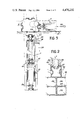
- FIG. 1 diagrammatically and in perspective a modular assembly according to the invention.
- FIG. 2 diagrammatically, the hollow profiled member located at the base of each panel of the assembly.
- FIG. 3 in more detailed manner, the assembly of a post and two panels.
- FIG. 4 the location of the fixing means between a post and a panel.
- FIG. 5 in more detailed manner, one of the said fixing means.
- FIG. 6 diagrammatically, an upper hollow member at the top of each panel.
- FIG. 7 another arrangement of the panels and posts.
- FIG. 8 diagrammatically and in exemplified manner, the different electrical connectors.
- FIG. 1 diagrammatically shows a modular assembly for the construction of the exhibition stand according to the invention.
- This modular assembly comprises two panels 1, 2 fixed to a post 3. It may also comprise other panels 4, 5, 6, 7, as well as other posts, such as e.g. post 8. These posts and panels rest by their base on an installation surface area 9. The different panels respectively rest on installation area 9 by means of base hollow profiled members 10, 11, 12, 13, 14, etc, which are fixed thereto.
- Each of the said members may contain one or more pipes 15, 16 carrying a fluid such as air for example, as well as electrical signal conductors 17.
- each post is hollow facing the base hollow profiled members in order to permit connections between the pipes of the different panels and the connection between these pipes and other pipes, as well as the connection between conductors of two panels or the connection of these conductors with other conductors, as will be shown in greater detail hereinafter.
- the panels are made from a rigid material, such as agglomerated wood, whilst the hollow profiled members are made e.g. from aluminium.
- the pipes such as 15 and 16, shown in exemplified manner in the drawing, make it possible to respectively supply the wash basin 19 or remove dirty water therefrom. It is obvious that the said pipes carrying water in the chosen example can also carry gaseous fluids such as compressed air.
- These pipes are located within base hollow profiles in the lower part thereof, whilst the electrical conductors 17 are located in the upper part of said base hollow profiles.
- these electrical conductors supply from a switchbox 20 power points such as 21 or light fittings 22, in the manner to be shown hereinafter. They also supply the telephone 23.
- the switchbox 20 is supplied by an electrical line 24. This line leads to the base hollow part of post 3, the distribution of the electric signals up to switchbox 20 being carried out by a not shown connector located in the base 18 of the post and by cable 25. It is obvious that the aforementioned connector can also distribute the electric signals by a line 54 in other panels, such as e.g. panel 6.
- this modular assembly also comprises an upper hollow profiled member, the latter being shown for the different panels at 26, 27, 28, 29, 30 etc.
- each post 3 is a hollow member permitting the passage of electrical signal conductors in the direction of the upper hollow profiled members.
- connectors 31 make it possible to connect the conductors 32 contained in post 3 to conductors 33 located in the upper hollow profiles.
- the conductors 32 contained in post 3 are connected by not shown means to other conductors in the base of post 3.
- the conductors 33 contained in the upper profiles can obviously be connected to other conductors contained in upper profiles of other panels or to other conductors contained in post 3.
- the upper and base hollow members can be sealed by covers, such as covers 43, 46.
- FIG. 2 diagrammatically shows in a perspective view the base hollowed profile member 10.
- the latter have at least one partition 34 subdividing the hollow member into a first lower part 35 housing the fluid transfer pipes (not shown in the drawing) and a second upper part 36 housing the electrical conductors (not shown in the drawing).
- This base profiled member is surmounted by a support 37 having a shape enabling it to support panel 1, as well as detachable coverings 38, 39, each of which covers faces of the said panels. These coverings will be described in greater detail hereinafter.
- the base hollow member 10 and the upper hollow member 26 have a shape making it possible to fix electrical components, such as power points 40, light fittings 22, etc.
- FIG. 1 shows vertical columns 41 arranged on one or both faces of each panel and which by means of an e.g. rack configuration make it possible to fit object supports such as switchbox 20, support 42 of telephone 23, the telephone switch or the support for washbasin 19.
- object supports such as switchbox 20, support 42 of telephone 23, the telephone switch or the support for washbasin 19.
- each base hollow member supporting each panel may also comprise at least one vertical partition 44 making it possible to subdivide the first and second lower and upper parts 35, 36 so as to separate the pipes and electrical conductors relative to each of the faces of panel 1.
- FIG. 1 also shows on each of the faces of each panel, the detachable covers 38, 39 integral with the base hollow member 12 and the upper hollow member 30, e.g. for panel 7.
- These detachable coverings are fixed to the said hollow members by means of grooves such as 45 (FIG. 2) made in the hollow members.
- the fitting of the detachable covering is shown at 47, whilst at 48 it is possible to see the structure of said covering in a more detailed manner.
- the covering is in fact constituted by a plate 49 enveloped in a decorative surface layer 50, each of whose faces 51, 52 can be given a different colouring. In this way, it is possible, by simply turning over the detachable covering, to change the appearance of the stand.
- Plate 49 is a rigid plate made from a laminated material or e.g. plastic.
- the decorative surface layer 50 is also interchangeable, so that it can easily be replaced and optionally other colours can be used.
- the modular assembly also comprises assembly means for each panel for the purpose of assembling the panels and the posts. It also comprises means for connecting the conductors and means for connecting the pipes at the end of each panel.
- FIG. 3 shows in more detailed manner, the installation of panels 1 and 2 and posts 3 of FIG. 1.
- the same elements carry the same references as in FIGS. 1 and 2.
- FIG. 3 also shows in greater detail a number of electrical conductors, which can be placed in upper and lower hollow members of each of the panels. It is obvious that this electrical installation is in no way limitative.
- cable 24 supplies telephone or electric signals in the direction of panels 1 or 2.
- This cable is obviously located in the upper part of the base hollow member of panel 2.
- Connectors such as 53 located at the base of post 3 make it possible to provide branches in the direction of switchbox 20, in the direction of other panels or in the direction of conductors located in the upper hollow members by means of conductors located in posts 3, e.g.
- each panel the conductors are contained in the base and upper hollow members and are provided with high-speed connection means, e.g. power point 56.
- the conductors coming from post 3 and which supply switchbox 20 are also provided with power points 58. These power points are in particular provided for the electrical signals in order to respect the safety standards.
- the power point 58 supplying switchbox 20 is a socket
- power point 56 supplying the conductors of panel 1 from said switchbox is a plug.
- the drawing also shows at the end of each panel and within the latter, profiles 55, 57, 59 making it possible to increase the strength of these panels and which also support vertical columns 41 for fitting object supports. It is also possible to see the power point 21 fixed to the base hollow member of panel 1.
- FIG. 4 shows diagrammatically panels 1 and 6 and post 3, as well as fixing means 60, 61 located at the ends of the base and upper hollow members 10 and 26 respectively enabling panel 1 and post 3 to be fixed together.
- the drawing also diagrammatically shows electrical conductors 24.
- FIG. 5 shows in detailed manner one of the fixing means enabling one of the panels to be fixed to post 3.
- These fixing means are described in French patent application Nos. 71 24863 and 73 45532. They are essentially constituted by a spindle 61 provided with a head 72 engaging in the trapezoidal groove of post 3. The initial position of this head before joining the panel to post 3 is shown by dotted lines to the right of the drawing.
- Spindle 61 is provided with a lug 62 which, at the time when the panel is pressed against the post, bears on a not shown cam enabling head 72 to be pivoted by 90°, so as to lock the panel.
- a spring 63 bears on a flange 64 of spindle 61 so as to force head 72 towards the outside of the panel before fitting the latter to post 3.
- a screw 75 makes it possible to complete the locking, when the panel is already fitted against the post.
- FIG. 6 shows in more detailed manner one of the upper hollow members 27.
- the said hollow member is in fact constituted by two integral parts.
- Upper part 65 serves to contain electrical conductors and to support e.g. strip lighting diagrammatically shown at 66, whilst the lower part 67 has a shape enabling it to hold in place the panel and the detachable coverings covering the latter.
- Post 3 facing said upper hollow member obviously has not specifically designated openings permitting the passage of electrical conductors, as well as the connection of said conductors to conductors in other panels or in post 3.
- FIG. 7 diagrammatically shows another relative arrangement of panels 1 and posts 3. According to this arrangement, the adjacent panels of each post are no longer in the extension of one another or at right angles, but instead form an angle exceeding e.g. 90°.
- FIG. 8 diagrammatically shows at a perspective in which is shown in exemplified manner the connections between the different electrical conductors of several panels and at b a diagrammatic plan view of one of these panels with the main conductors contained therein. These panels are designated 1, 2 and 4 in FIG. 8.
- the plugs are shown symbolically and designated 73, whilst the sockets are shown symbolically and designated 74.
- the drawing also shows a switchbox 20 to which electric power is supplied by a not shown line.
- the conductors leaving this switchbox have terminal sockets 74, which can be connected to plug 73, which are themselves connected either to conductors located in the base hollow members or to conductors located in a post.
- the male connector is located to the right of the panel when the latter is viewed from the front, whilst the female connector is positioned to the left thereof.
- the partitions are identical and their positions can be reversed.
- the modular assembly complies with the electrical safety standards, because the power is always supplied in the female connector.
- the same arrangement of connectors can obviously be used for a telephone line.
- the panels, posts, hollow members, etc. can have random dimensions, as a function of the dimensions of the stands and the panels which are in one-piece.
Landscapes
- Engineering & Computer Science (AREA)
- Architecture (AREA)
- Civil Engineering (AREA)
- Structural Engineering (AREA)
- Physics & Mathematics (AREA)
- Electromagnetism (AREA)
- Installation Of Indoor Wiring (AREA)
Abstract
Description
Claims (3)
Applications Claiming Priority (2)
| Application Number | Priority Date | Filing Date | Title |
|---|---|---|---|
| FR8112517A FR2508524A1 (en) | 1981-06-25 | 1981-06-25 | MODULAR ASSEMBLY FOR CONSTRUCTING AN EXHIBITION LOCATION |
| FR8112517 | 1981-06-26 |
Publications (1)
| Publication Number | Publication Date |
|---|---|
| US4470232A true US4470232A (en) | 1984-09-11 |
Family
ID=9259872
Family Applications (1)
| Application Number | Title | Priority Date | Filing Date |
|---|---|---|---|
| US06/331,266 Expired - Fee Related US4470232A (en) | 1981-06-25 | 1981-12-16 | Modular assembly for constructing an exhibition stand |
Country Status (7)
| Country | Link |
|---|---|
| US (1) | US4470232A (en) |
| AT (1) | AT375129B (en) |
| BE (1) | BE893635A (en) |
| CA (1) | CA1178417A (en) |
| CH (1) | CH649339A5 (en) |
| DE (1) | DE8218305U1 (en) |
| FR (1) | FR2508524A1 (en) |
Cited By (37)
| Publication number | Priority date | Publication date | Assignee | Title |
|---|---|---|---|---|
| US4683695A (en) * | 1985-09-18 | 1987-08-04 | Olivetti Synthesis, S.P.A. | Channelled base member for divider panels |
| US4713918A (en) * | 1986-01-30 | 1987-12-22 | Nabisco Brands, Inc. | Modular wall system |
| US4762072A (en) * | 1986-10-07 | 1988-08-09 | Westinghouse Electric Corp. | Desk and space dividing wall panel assembly |
| US4800695A (en) * | 1987-10-02 | 1989-01-31 | National Gypsum Company | Electrical raceway floor track |
| US4932181A (en) * | 1988-11-23 | 1990-06-12 | The Shaw-Walker Company | Base assembly for an open office partition panel |
| US5029423A (en) * | 1989-10-24 | 1991-07-09 | Kornylak Corporation | Vibration resistant building construction |
| US5152698A (en) * | 1989-02-07 | 1992-10-06 | Steelcase Inc. | Floor track system for office furniture and the like |
| US5207037A (en) * | 1988-12-05 | 1993-05-04 | Lippert Holding Company | Wall partition units |
| US5452547A (en) * | 1992-01-10 | 1995-09-26 | Steelcase Inc. | Dynamic workspace module |
| US5511348A (en) | 1990-02-14 | 1996-04-30 | Steelcase Inc. | Furniture system |
| US5556873A (en) * | 1993-02-24 | 1996-09-17 | Rhone-Poulenc Inc. | Pesticidal 1-aryl-5-(substituted alkyl (thio) amido)pyrazoles |
| US5651219A (en) * | 1993-10-29 | 1997-07-29 | Steelcase Inc. | Dynamic workspace module |
| US5675949A (en) * | 1993-05-18 | 1997-10-14 | Steelcase Inc. | Utility distribution system for open office plans and the like |
| WO1998028503A1 (en) * | 1996-12-24 | 1998-07-02 | Steelcase Inc. | Knock-down portable partition system |
| US5784843A (en) * | 1994-12-30 | 1998-07-28 | Steelcase Inc. | Integrated prefabricated furniture system for fitting-out open plan building space |
| US5806261A (en) * | 1994-03-10 | 1998-09-15 | Plascore, Inc. | Head track for a wall system |
| US5899025A (en) * | 1996-03-22 | 1999-05-04 | Steelcase Inc. | Furniture system (pathways-spaceframe) |
| US5901512A (en) * | 1996-04-08 | 1999-05-11 | Knoll, Inc. | Hardwiring race for office partitions |
| US6003275A (en) | 1990-02-14 | 1999-12-21 | Steelcase Development Inc. | Furniture system |
| US6067762A (en) * | 1994-12-30 | 2000-05-30 | Steelcase Development Inc. | Integrated furniture system |
| US6079173A (en) * | 1997-05-15 | 2000-06-27 | Steelcase Development Inc. | Knock-down portable partition system |
| US6094875A (en) * | 1996-07-30 | 2000-08-01 | Burkiss Inc. | Removable wall assembly |
| US6134844A (en) | 1990-02-14 | 2000-10-24 | Steelcase Inc. | Method and apparatus for displaying information |
| US6158179A (en) * | 1998-03-10 | 2000-12-12 | Steelcase Development Inc. | Overhead structures for wall system |
| US6170200B1 (en) | 1990-02-14 | 2001-01-09 | Steelcase Development Inc. | Furniture system |
| US6311441B1 (en) * | 2000-03-13 | 2001-11-06 | The Artglo Company | Panel-based modular wall system |
| US6311440B1 (en) | 1993-05-18 | 2001-11-06 | Steelcase Development Corporation | Floor mounted utility post |
| US6442909B2 (en) | 1996-12-24 | 2002-09-03 | Steelcase Development Corporation | Knock-down portable partition system |
| US6490829B1 (en) | 1988-07-29 | 2002-12-10 | Herman Miller Inc. | Free standing modular architectural beam system |
| US6497075B1 (en) | 1988-07-29 | 2002-12-24 | Herman Miller Inc. | Free standing modular architectural beam system |
| US6546684B2 (en) | 1998-04-15 | 2003-04-15 | Steelcase Development Corporation | Partition panel |
| US6817478B2 (en) | 2001-05-31 | 2004-11-16 | Frank Venegas, Jr. | Modular office furniture |
| US6910306B2 (en) | 1996-12-24 | 2005-06-28 | Steelcase Development Corporation | Knock-down portable partition system |
| US20080191554A1 (en) * | 2007-02-09 | 2008-08-14 | Andrew Desmond Rowe | Power Supply System |
| WO2008135850A2 (en) * | 2007-05-08 | 2008-11-13 | Bau-How As | A wall-related construction element (connection devices) |
| US7827920B2 (en) | 1998-10-13 | 2010-11-09 | Herman Miller Inc. | Work space management and furniture system |
| WO2020231247A1 (en) * | 2019-05-16 | 2020-11-19 | Aragones Pardo Miguel Angel | Structure for aluminum houses |
Families Citing this family (13)
| Publication number | Priority date | Publication date | Assignee | Title |
|---|---|---|---|---|
| DE3222018A1 (en) * | 1982-06-11 | 1983-12-15 | Ideal-Standard Gmbh, 5300 Bonn | PARTITION WALL SYSTEM IN THE MODULAR GRID |
| US4685255A (en) * | 1984-09-10 | 1987-08-11 | Herman Miller, Inc. | Work space management system |
| US4876835A (en) * | 1984-09-10 | 1989-10-31 | Herman Miller, Inc. | Work space management system |
| FR2597172B1 (en) * | 1986-04-11 | 1988-08-05 | Chenel Guy | DEVICE FOR ASSEMBLING STAND FRAME FOR TEMPORARY EXPOSURE |
| FR2600726B2 (en) * | 1986-04-11 | 1988-11-10 | Chenel Guy | DEVICE FOR ASSEMBLING STAND FRAME FOR TEMPORARY EXPOSURE. |
| US4880026A (en) * | 1988-07-28 | 1989-11-14 | Parapluie, Ltd. | Integrated free-standing vehicle detailing service center |
| DE3834951C2 (en) * | 1988-10-13 | 1995-12-07 | Werndl Wilhelm Gmbh & Co Kg | Linkable partition |
| GB2233684B (en) * | 1989-05-12 | 1993-05-26 | Environmental Panelling Syst | Demountable wall panelling |
| NL8902770A (en) * | 1989-11-08 | 1991-06-03 | Holding Tech Handels En Advies | MODULAR INTERIOR CONSTRUCTION SYSTEM. |
| US5746034B1 (en) * | 1994-12-30 | 2000-10-17 | Steelcase Inc | Partition system |
| US7178300B2 (en) | 2002-09-30 | 2007-02-20 | Krueger International, Inc. | Latch-type tile mounting system |
| DE10314685B4 (en) * | 2003-03-26 | 2006-03-30 | GfP (Gesellschaft für Produktivitätsplanung und Produktentwicklung) mbH | Media supply system |
| AT512496B1 (en) * | 2012-04-13 | 2013-09-15 | Richard Pedri | Flexible wall module |
Citations (20)
| Publication number | Priority date | Publication date | Assignee | Title |
|---|---|---|---|---|
| US1718253A (en) * | 1929-06-25 | Wall conduit | ||
| US1718252A (en) * | 1927-05-16 | 1929-06-25 | Herbert N Putnam | Wall conduit |
| US1798280A (en) * | 1929-06-20 | 1931-03-31 | Sorensen Niels Chester | Wall construction |
| US2000243A (en) * | 1932-06-20 | 1935-05-07 | United States Gypsum Co | Wall construction |
| US2187408A (en) * | 1939-02-03 | 1940-01-16 | Kaufmann Dept Stores Inc | Fitting room construction |
| US2399978A (en) * | 1943-08-09 | 1946-05-07 | Byron J Bartholomew | Prefabricated wallboard construction |
| US2808136A (en) * | 1953-01-02 | 1957-10-01 | Andrew B Hammitt | Partition construction |
| US2934180A (en) * | 1955-01-18 | 1960-04-26 | Andrew B Hammitt | Structural element |
| US3159882A (en) * | 1962-06-12 | 1964-12-08 | John H Slayter | Building construction |
| US3293813A (en) * | 1964-02-12 | 1966-12-27 | James W Emmons | Partition wall having i-section frame |
| US3321878A (en) * | 1964-03-10 | 1967-05-30 | Reynolds Metals Co | Baseboard construction |
| US3377756A (en) * | 1964-10-22 | 1968-04-16 | Movable Interior Products | Demountable building partition construction |
| US3611653A (en) * | 1970-04-13 | 1971-10-12 | Daniel L Zinn | Sound attenuation wall partition |
| US4032821A (en) * | 1976-04-02 | 1977-06-28 | Mcgraw-Edison Company | Utility distribution console |
| US4067165A (en) * | 1976-11-19 | 1978-01-10 | Hiebert, Inc. | Panel system |
| US4214799A (en) * | 1979-08-01 | 1980-07-29 | Bunker Ramo Corporation | Movable and pre-wired wall structure |
| US4232183A (en) * | 1977-08-29 | 1980-11-04 | Person Nelson H | Electrical connection system for panel structures |
| US4239932A (en) * | 1979-01-18 | 1980-12-16 | Gf Business Equipment, Inc. | Partition wiring system |
| US4270020A (en) * | 1979-11-21 | 1981-05-26 | Gf Business Equipment, Inc. | Partition wiring system |
| US4308418A (en) * | 1979-11-06 | 1981-12-29 | Steelcase Inc. | Arrangement for hard wiring movable room divider panels |
-
1981
- 1981-06-25 FR FR8112517A patent/FR2508524A1/en active Granted
- 1981-12-16 US US06/331,266 patent/US4470232A/en not_active Expired - Fee Related
- 1981-12-18 CA CA000392657A patent/CA1178417A/en not_active Expired
-
1982
- 1982-06-22 CH CH3818/82A patent/CH649339A5/en not_active IP Right Cessation
- 1982-06-24 BE BE0/208436A patent/BE893635A/en not_active IP Right Cessation
- 1982-06-24 AT AT0244382A patent/AT375129B/en not_active IP Right Cessation
- 1982-06-25 DE DE19828218305U patent/DE8218305U1/en not_active Expired
Patent Citations (20)
| Publication number | Priority date | Publication date | Assignee | Title |
|---|---|---|---|---|
| US1718253A (en) * | 1929-06-25 | Wall conduit | ||
| US1718252A (en) * | 1927-05-16 | 1929-06-25 | Herbert N Putnam | Wall conduit |
| US1798280A (en) * | 1929-06-20 | 1931-03-31 | Sorensen Niels Chester | Wall construction |
| US2000243A (en) * | 1932-06-20 | 1935-05-07 | United States Gypsum Co | Wall construction |
| US2187408A (en) * | 1939-02-03 | 1940-01-16 | Kaufmann Dept Stores Inc | Fitting room construction |
| US2399978A (en) * | 1943-08-09 | 1946-05-07 | Byron J Bartholomew | Prefabricated wallboard construction |
| US2808136A (en) * | 1953-01-02 | 1957-10-01 | Andrew B Hammitt | Partition construction |
| US2934180A (en) * | 1955-01-18 | 1960-04-26 | Andrew B Hammitt | Structural element |
| US3159882A (en) * | 1962-06-12 | 1964-12-08 | John H Slayter | Building construction |
| US3293813A (en) * | 1964-02-12 | 1966-12-27 | James W Emmons | Partition wall having i-section frame |
| US3321878A (en) * | 1964-03-10 | 1967-05-30 | Reynolds Metals Co | Baseboard construction |
| US3377756A (en) * | 1964-10-22 | 1968-04-16 | Movable Interior Products | Demountable building partition construction |
| US3611653A (en) * | 1970-04-13 | 1971-10-12 | Daniel L Zinn | Sound attenuation wall partition |
| US4032821A (en) * | 1976-04-02 | 1977-06-28 | Mcgraw-Edison Company | Utility distribution console |
| US4067165A (en) * | 1976-11-19 | 1978-01-10 | Hiebert, Inc. | Panel system |
| US4232183A (en) * | 1977-08-29 | 1980-11-04 | Person Nelson H | Electrical connection system for panel structures |
| US4239932A (en) * | 1979-01-18 | 1980-12-16 | Gf Business Equipment, Inc. | Partition wiring system |
| US4214799A (en) * | 1979-08-01 | 1980-07-29 | Bunker Ramo Corporation | Movable and pre-wired wall structure |
| US4308418A (en) * | 1979-11-06 | 1981-12-29 | Steelcase Inc. | Arrangement for hard wiring movable room divider panels |
| US4270020A (en) * | 1979-11-21 | 1981-05-26 | Gf Business Equipment, Inc. | Partition wiring system |
Non-Patent Citations (1)
| Title |
|---|
| Sweets Catalog File; 1979, 11.27 a/Fr., p. 42; 11.27 a/Ger., p. 39. * |
Cited By (61)
| Publication number | Priority date | Publication date | Assignee | Title |
|---|---|---|---|---|
| US4683695A (en) * | 1985-09-18 | 1987-08-04 | Olivetti Synthesis, S.P.A. | Channelled base member for divider panels |
| US4713918A (en) * | 1986-01-30 | 1987-12-22 | Nabisco Brands, Inc. | Modular wall system |
| US4762072A (en) * | 1986-10-07 | 1988-08-09 | Westinghouse Electric Corp. | Desk and space dividing wall panel assembly |
| US4800695A (en) * | 1987-10-02 | 1989-01-31 | National Gypsum Company | Electrical raceway floor track |
| US6497075B1 (en) | 1988-07-29 | 2002-12-24 | Herman Miller Inc. | Free standing modular architectural beam system |
| US6490829B1 (en) | 1988-07-29 | 2002-12-10 | Herman Miller Inc. | Free standing modular architectural beam system |
| US4932181A (en) * | 1988-11-23 | 1990-06-12 | The Shaw-Walker Company | Base assembly for an open office partition panel |
| AU614885B2 (en) * | 1988-11-23 | 1991-09-12 | Shaw-Walker Company, The | A base assembly for an open office partition panel |
| US5207037A (en) * | 1988-12-05 | 1993-05-04 | Lippert Holding Company | Wall partition units |
| US5152698A (en) * | 1989-02-07 | 1992-10-06 | Steelcase Inc. | Floor track system for office furniture and the like |
| US5029423A (en) * | 1989-10-24 | 1991-07-09 | Kornylak Corporation | Vibration resistant building construction |
| US6922949B2 (en) * | 1990-02-14 | 2005-08-02 | Steelcase Development Corporation | Furniture system |
| US5511348A (en) | 1990-02-14 | 1996-04-30 | Steelcase Inc. | Furniture system |
| US20030200704A1 (en) * | 1990-02-14 | 2003-10-30 | Steelcase Development Corporation | Furniture system |
| US6629386B1 (en) | 1990-02-14 | 2003-10-07 | Steelcase Development Corporation | Furniture system |
| US6003275A (en) | 1990-02-14 | 1999-12-21 | Steelcase Development Inc. | Furniture system |
| US5724778A (en) | 1990-02-14 | 1998-03-10 | Steelcase Inc. | Furniture system |
| US6170200B1 (en) | 1990-02-14 | 2001-01-09 | Steelcase Development Inc. | Furniture system |
| US6134844A (en) | 1990-02-14 | 2000-10-24 | Steelcase Inc. | Method and apparatus for displaying information |
| US5687513A (en) * | 1992-01-10 | 1997-11-18 | Steelcase Inc. | Dynamic workspace module |
| US5452547A (en) * | 1992-01-10 | 1995-09-26 | Steelcase Inc. | Dynamic workspace module |
| US5556873A (en) * | 1993-02-24 | 1996-09-17 | Rhone-Poulenc Inc. | Pesticidal 1-aryl-5-(substituted alkyl (thio) amido)pyrazoles |
| US6311440B1 (en) | 1993-05-18 | 2001-11-06 | Steelcase Development Corporation | Floor mounted utility post |
| US5794392A (en) * | 1993-05-18 | 1998-08-18 | Steelcase Inc. | Utility distribution system for open office plans and the like |
| US5768840A (en) * | 1993-05-18 | 1998-06-23 | Steelcase Inc. | Integrated utility distribution and panel system |
| US5996294A (en) * | 1993-05-18 | 1999-12-07 | Steelcase Development, Inc. | Utility distribution system for open office plans and the like |
| US5697193A (en) * | 1993-05-18 | 1997-12-16 | Steelcase Inc. | Utility distribution system for open office plans and the like |
| US5675949A (en) * | 1993-05-18 | 1997-10-14 | Steelcase Inc. | Utility distribution system for open office plans and the like |
| US6430882B1 (en) | 1993-05-18 | 2002-08-13 | Steelcase Development Corporation | Floor mounted utility post |
| US5651219A (en) * | 1993-10-29 | 1997-07-29 | Steelcase Inc. | Dynamic workspace module |
| US5806261A (en) * | 1994-03-10 | 1998-09-15 | Plascore, Inc. | Head track for a wall system |
| US6128873A (en) * | 1994-12-30 | 2000-10-10 | Steelcase Development Inc. | Integrated prefabricated furniture system for fitting-out open plan building space |
| US6067762A (en) * | 1994-12-30 | 2000-05-30 | Steelcase Development Inc. | Integrated furniture system |
| US5784843A (en) * | 1994-12-30 | 1998-07-28 | Steelcase Inc. | Integrated prefabricated furniture system for fitting-out open plan building space |
| US6276102B1 (en) | 1994-12-30 | 2001-08-21 | Steelcase Development Corporation | Integrated prefabricated furniture system for fitting-out open plan building space |
| US5809708A (en) * | 1994-12-30 | 1998-09-22 | Steelcase Inc. | Integrated prefabricated furniture system for fitting-out open plan building space |
| US5899025A (en) * | 1996-03-22 | 1999-05-04 | Steelcase Inc. | Furniture system (pathways-spaceframe) |
| US5901512A (en) * | 1996-04-08 | 1999-05-11 | Knoll, Inc. | Hardwiring race for office partitions |
| US6094875A (en) * | 1996-07-30 | 2000-08-01 | Burkiss Inc. | Removable wall assembly |
| US6442909B2 (en) | 1996-12-24 | 2002-09-03 | Steelcase Development Corporation | Knock-down portable partition system |
| US6910306B2 (en) | 1996-12-24 | 2005-06-28 | Steelcase Development Corporation | Knock-down portable partition system |
| US7565772B2 (en) | 1996-12-24 | 2009-07-28 | Steelcase, Inc. | Knock-down portable partition system |
| WO1998028503A1 (en) * | 1996-12-24 | 1998-07-02 | Steelcase Inc. | Knock-down portable partition system |
| US7448168B2 (en) | 1996-12-24 | 2008-11-11 | Steelcase Inc. | Knock-down portable partition system |
| US6009675A (en) * | 1996-12-24 | 2000-01-04 | Steelcase Development Inc. | Knock-down portable partition system |
| US20050144855A1 (en) * | 1996-12-24 | 2005-07-07 | Waalkes Michael L. | Knock-down portable partition system |
| US6079173A (en) * | 1997-05-15 | 2000-06-27 | Steelcase Development Inc. | Knock-down portable partition system |
| US6098358A (en) * | 1997-05-15 | 2000-08-08 | Steelcase Development Inc. | Knock-down portable partition system |
| US6158179A (en) * | 1998-03-10 | 2000-12-12 | Steelcase Development Inc. | Overhead structures for wall system |
| US6546684B2 (en) | 1998-04-15 | 2003-04-15 | Steelcase Development Corporation | Partition panel |
| US7827920B2 (en) | 1998-10-13 | 2010-11-09 | Herman Miller Inc. | Work space management and furniture system |
| US6311441B1 (en) * | 2000-03-13 | 2001-11-06 | The Artglo Company | Panel-based modular wall system |
| US6817478B2 (en) | 2001-05-31 | 2004-11-16 | Frank Venegas, Jr. | Modular office furniture |
| GB2448306B (en) * | 2007-02-09 | 2009-12-23 | Fitzgerald Lighting Ltd | A power supply system |
| GB2448306A (en) * | 2007-02-09 | 2008-10-15 | Fitzgerald Lighting Ltd | A power supply system for an exhibition stand |
| US7728460B2 (en) | 2007-02-09 | 2010-06-01 | Lightpower Expo Limited | Power supply system |
| US20080191554A1 (en) * | 2007-02-09 | 2008-08-14 | Andrew Desmond Rowe | Power Supply System |
| AU2008200630B2 (en) * | 2007-02-09 | 2011-08-25 | Richards, Keith John | A power supply system |
| WO2008135850A3 (en) * | 2007-05-08 | 2008-12-31 | Bau How As | A wall-related construction element (connection devices) |
| WO2008135850A2 (en) * | 2007-05-08 | 2008-11-13 | Bau-How As | A wall-related construction element (connection devices) |
| WO2020231247A1 (en) * | 2019-05-16 | 2020-11-19 | Aragones Pardo Miguel Angel | Structure for aluminum houses |
Also Published As
| Publication number | Publication date |
|---|---|
| FR2508524A1 (en) | 1982-12-31 |
| FR2508524B1 (en) | 1984-06-29 |
| ATA244382A (en) | 1983-11-15 |
| CH649339A5 (en) | 1985-05-15 |
| CA1178417A (en) | 1984-11-27 |
| AT375129B (en) | 1984-07-10 |
| BE893635A (en) | 1982-12-27 |
| DE8218305U1 (en) | 1983-03-31 |
Similar Documents
| Publication | Publication Date | Title |
|---|---|---|
| US4470232A (en) | Modular assembly for constructing an exhibition stand | |
| US4795355A (en) | Movable panel member incorporating an integrated electrical current distributing busbar | |
| CA1140242A (en) | Versatile, electrified space dividing wall panel system | |
| US6490829B1 (en) | Free standing modular architectural beam system | |
| EP0617178B1 (en) | Wall panel system | |
| DE2166970C2 (en) | Electrical installation system in rooms | |
| US5974742A (en) | Free standing modular furniture and wall system | |
| US7673422B2 (en) | Modular buildings | |
| US6128876A (en) | Tile panel system | |
| CA2191354C (en) | Electrical interconnection assembly | |
| US4642946A (en) | Modular display system | |
| US20080236056A1 (en) | Modular buildings | |
| US6364678B1 (en) | Power column | |
| US5743052A (en) | Business recovery installation and method for its erection | |
| US3587197A (en) | Prefabricated cantilevered building structure | |
| CN111119566B (en) | Covering or awning on a car, boat, etc. room frame, unit covering or awning on a car, boat, etc. room and extending formula cube covering or awning on a car, boat, etc. room group | |
| CA2195465C (en) | Junction block wall mounting arrangement | |
| US3888059A (en) | Partition wall construction | |
| US5081809A (en) | Demountable wall panelling | |
| EP1196668B1 (en) | Building system | |
| US5154030A (en) | Modular office partitioning system | |
| CN214169712U (en) | Architectural decoration system | |
| KR200228552Y1 (en) | Prefabricated partition | |
| JPH0540671Y2 (en) | ||
| US20010037890A1 (en) | System of structures for open offices |
Legal Events
| Date | Code | Title | Description |
|---|---|---|---|
| AS | Assignment |
Owner name: SOCIETE FRANCAISE D'EXPOSITIONS; 34, RUE DE HAMEAU Free format text: ASSIGNMENT OF ASSIGNORS INTEREST.;ASSIGNORS:CONDEVAUX, GEORGES;COMTE, GERARD;REEL/FRAME:004025/0821 Effective date: 19820726 Owner name: ENTREPRISES ELECTRIQUES MORS-JEAN ET BOUCHON; 280, Free format text: ASSIGNMENT OF ASSIGNORS INTEREST.;ASSIGNORS:CONDEVAUX, GEORGES;COMTE, GERARD;REEL/FRAME:004025/0821 Effective date: 19820726 |
|
| FEPP | Fee payment procedure |
Free format text: PAYOR NUMBER ASSIGNED (ORIGINAL EVENT CODE: ASPN); ENTITY STATUS OF PATENT OWNER: LARGE ENTITY |
|
| FPAY | Fee payment |
Year of fee payment: 4 |
|
| REMI | Maintenance fee reminder mailed | ||
| LAPS | Lapse for failure to pay maintenance fees | ||
| FP | Lapsed due to failure to pay maintenance fee |
Effective date: 19920913 |
|
| FP | Lapsed due to failure to pay maintenance fee |
Effective date: 19920913 |
|
| STCH | Information on status: patent discontinuation |
Free format text: PATENT EXPIRED DUE TO NONPAYMENT OF MAINTENANCE FEES UNDER 37 CFR 1.362 |