US4479385A - Double resonator cantilever accelerometer - Google Patents
Double resonator cantilever accelerometer Download PDFInfo
- Publication number
- US4479385A US4479385A US06/422,515 US42251582A US4479385A US 4479385 A US4479385 A US 4479385A US 42251582 A US42251582 A US 42251582A US 4479385 A US4479385 A US 4479385A
- Authority
- US
- United States
- Prior art keywords
- resonator
- base
- accelerometer
- mass
- transducer
- Prior art date
- Legal status (The legal status is an assumption and is not a legal conclusion. Google has not performed a legal analysis and makes no representation as to the accuracy of the status listed.)
- Expired - Fee Related
Links
Images


Classifications
-
- G—PHYSICS
- G01—MEASURING; TESTING
- G01P—MEASURING LINEAR OR ANGULAR SPEED, ACCELERATION, DECELERATION, OR SHOCK; INDICATING PRESENCE, ABSENCE, OR DIRECTION, OF MOVEMENT
- G01P15/00—Measuring acceleration; Measuring deceleration; Measuring shock, i.e. sudden change of acceleration
- G01P15/02—Measuring acceleration; Measuring deceleration; Measuring shock, i.e. sudden change of acceleration by making use of inertia forces using solid seismic masses
- G01P15/08—Measuring acceleration; Measuring deceleration; Measuring shock, i.e. sudden change of acceleration by making use of inertia forces using solid seismic masses with conversion into electric or magnetic values
-
- Y—GENERAL TAGGING OF NEW TECHNOLOGICAL DEVELOPMENTS; GENERAL TAGGING OF CROSS-SECTIONAL TECHNOLOGIES SPANNING OVER SEVERAL SECTIONS OF THE IPC; TECHNICAL SUBJECTS COVERED BY FORMER USPC CROSS-REFERENCE ART COLLECTIONS [XRACs] AND DIGESTS
- Y10—TECHNICAL SUBJECTS COVERED BY FORMER USPC
- Y10S—TECHNICAL SUBJECTS COVERED BY FORMER USPC CROSS-REFERENCE ART COLLECTIONS [XRACs] AND DIGESTS
- Y10S73/00—Measuring and testing
- Y10S73/01—Vibration
Definitions
- the present invention relates generally to accelerometers and more particularly to a mass loaded cantilever accelerometer.
- the United States Government has rights in this invention pursuant to Contract No. DE-AC04-76DP00789 between the Department of Energy and Sandia Corporation.
- a useful accelerometer must be sensitive to desired accelerations and insensitive to spurious, undesirable accelerations.
- an accelerometer for measuring the acceleration of a rocket must be sensitive to acceleration of the rocket in the direction of motion and insensitive to the many accelerations in other directions caused by vibration of the rocket.
- the accelerometer should also be capable of providing a digital output proportional to acceleration for use with conventional digital equipment.
- a later digital accelerometer is shown in U.S. Pat. No. 3,269,192 of Southworth, Jr., et. al.
- a tuning fork has two tines clamped at each end and vibrated 180° out of phase.
- a dense inertial proof mass is secured to one pair of ends of the tines and supported against cross-axis movement perpendicular to the tines while being free to move longitudinally so as to extend or compress the tines when the mass is accelerated.
- Southworth does incorporate the double-ended tuning fork design of this invention, it utilizes a large mass (as opposed to the small mass of the invention) which is constrained to motion along the tine axis. No such constraints are part of the invention because the invention measures acceleration perpendicular to the tine axis. In Southworth, movement of the mass along the axis either puts both tuning forks in tension or in compression, while movement of the mass of the invention causes one tuning fork to be compressed and the other to be under tension. As a result of these differences in construction, the invention has greater sensitivity and reliability than Southworth.
- a miniature quartz transducer which is utilized in the preferred embodiment of this invention is shown in U.S. Pat. No. 4,215,570 of Eer Nisse.
- a rectangular plate of quartz crystal has a continuous end portion at either end and a longitudinal slot connecting each end portion, forming a pair of parallel, spaced beams.
- Metal electrodes are formed on the transducer for exciting it and providing an electrical output therefrom.
- the accelerometer of this invention may consist of a base and an acceleration sensitive resonator fastened to the base, the resonator consisting of a mass and pair of elongate resonating members, each member having one end rigidly fastened to the base and an opposed end rigidly fastened to the mass, the members being spaced apart.
- each resonating member comprises a double-ended tuning fork which is aligned with, and parallel to, the other tuning fork.
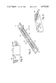
- FIG. 1 shows a side view of the invention under an accelerating force.
- FIG. 2 is a perspective view of a preferred embodiment of a resonating member.
- FIG. 3 shows circuitry which may be used with the invention.
- FIG. 4 shows a second embodiment of the invention.
- FIG. 5 shows a third embodiment of the invention.
- the accelerometer of this invention broadly consists of base 1 and cantilever acceleration sensitive resonator 10 affixed to base 1.
- base 1 comprises mount 2 and spacer 3
- resonator 10 comprises upper resonator 11, lower resonator 12, and spacer mass 20.
- Resonator 10 is attached at one end to spacer 3.
- Electrical connections 25 are provided to energize each resonator and provide for detection of changes in frequency as disclosed hereinafter.
- each resonator 11 and lower resonator 12 is excited, causing the resonators to vibrate.
- each resonator vibrates "independently" of the other resonator, as absolutely no coupling between resonators is desirable.
- the frequency of each resonator is dependent on the state of tensile or compressive stress in the resonator and is therefore sensitive to acceleration forces present. These forces are applied perpendicular to the axis of the resonator as shown in FIG. 1, causing one bar to stretch and the other bar to compress.
- the changes in frequency caused by the force may be detected as hereinafter described to provide a digital output proportional to the applied acceleration.
- each resonator 11, 12 may comprise a double-ended tuning fork of the type disclosed in aforementioned U.S. Pat. No. 4,215,570.
- FIG. 2 shows a resonator as disclosed in this patent, where either of resonators 11, 12 comprise two tuning forks secured end-to-end.
- This resonator has two opposed end portions 13, and a longitudinal slot 14 extending therebetween. Vibratory portions 15 extend between the end portions on either side of slot 14.
- the rectangular resonator is constructed from quartz and has electrode patterns 16 and 17 plated on its surface for application of electrical signals as described hereafter.
- a complete description of resonators 11, 12 may be found in U.S. Pat. No. 4,215,570, the disclosure of which patent is incorporated herein by reference.
- the theory of operation of the invention is as follows.
- the frequency of a vibrating beam under tension is expressed mathematically as a power series function of the applied axial load T as ##EQU1## or, to first approximation ##EQU2##
- L is the length of the beam
- E its modulus of elasticity
- I is the moment of inertia relative to its vibrational direction
- w and t the width and thickness, respectively, of the beam
- S the stress in the beam produced by the load T.
- the stress S in the top beam under an acceleration load on the mass m, as shown in FIG. 1, is a tensile stress while the stress in the bottom beam is compressive.
- the frequency of the top beam resonator therefore is shifted, under an acceleration induced stress, positively, while the frequency of the bottom beam is shifted negatively.
- the difference frequency between the two beams is thus seen to be twice that of the frequency shift in each beam, according to the following formula: ##EQU3## where fou and fol are the frequencies of the unaccelerated upper and lower resonator sensors and ⁇ fg is the frequency shift caused by the acceleration g.
- oscillator 31 includes quartz resonator beam 11 and is connected thereto by wires 25 to connection points 16, 17.
- the output of oscillator 31 is multiplied by frequency multiplier 32 and fed to gated counter 33.
- Resonator beam 12 is likewise connected to an identical circuit which includes counter 34.
- each counter 33, 34 is interrogated every T-seconds by a time-interval gate signal generated from a control clock (not shown).
- the counts recorded by counter 33 are dumped into latch 35 while the counts in counter 34 are dumped into latch 36.
- Difference counter 35 first takes the difference between two successive counts from counter 33 and then takes the difference between two successive counts from counter 34. These values are then subtracted from each other to provide the acceleration produced frequency shift over the time interval over the gate signal. By first taking the differences between two successive counts, the system does not lose counts and the typical plus or minus one count per sampling time electronic counting error is avoided.
- each of beams 11, 12 is approximately 400 mils long, 5 mils thick and 20 mils wide.
- Mass 20 is in the form of 16 milligrams of gold approximately 10 mils thick by 70 mils wide by 70 mils long.
- the resonance of each beam is approximately 40 kHz, and the difference frequency noted upon an applied acceleration is approximately 100 to 300 Hz.
- the device has a sensitivity of approximately 2 Hz/g.
- the cantilever structure may be configured as shown in FIG. 4 with one active resonator member 40 and one inactive beam member 41.
- an additional "thermally matched", but not mass loaded, resonator 42 is used in a difference frequency operational mode to achieve an acceleration sensitive difference frequency that is not temperature dependent.
- this embodiment has reduced sensitivity compared to the embodiment of FIG. 1, it has an advantage in that there is no mechanical coupling between the resonator members.
- the accelerometer will be sensitive to transverse accelerations with a sensitivity ratio of 50 to 100 times its sensitivity to axial accelerations.
- This axial sensitivity can be compensated for by the configuration of FIG. 5 wherein two cantilevers 10a, 10b are employed in a mutually perpendicular orientation, each cantilever being a parallel beam resonator in accordance with the embodiment of FIG. 1.
- the resonators may be plan rectangular sheets rather than the double-ended tuning forks disclosed, or may have configurations other than rectangular.
- the resonators may not necessarily be parallel to one another or aligned one above the other, although this arrangement does minimize the effects of undesirable torques on the resonators.
- An accelerometer constructed in accordance with the principles of this invention will provide a sensitive measure of acceleration in a direction transverse to the axis of the resonator. It is intended that the scope of the invention be defined by the claims appended hereto.
Abstract
A digital quartz accelerometer includes a pair of spaced double-ended tuning forks fastened at one end to a base and at the other end through a spacer mass. Transverse movement of the resonator members stresses one and compresses the other, providing a differential frequency output which is indicative of acceleration.
Description
The present invention relates generally to accelerometers and more particularly to a mass loaded cantilever accelerometer. The United States Government has rights in this invention pursuant to Contract No. DE-AC04-76DP00789 between the Department of Energy and Sandia Corporation.
A useful accelerometer must be sensitive to desired accelerations and insensitive to spurious, undesirable accelerations. For instance, an accelerometer for measuring the acceleration of a rocket must be sensitive to acceleration of the rocket in the direction of motion and insensitive to the many accelerations in other directions caused by vibration of the rocket. In addition, the accelerometer should also be capable of providing a digital output proportional to acceleration for use with conventional digital equipment.
One example of an early digital accelerometer is shown in U.S. Pat. No. 2,928,668 of Blasingame, where an accelerometer produces an output of two alternating voltages whose frequencies are related to the acceleration of the instrument. In Blasingame, a reed with a magnet on its end is caused to vibrate at its natural frequency by an electrical pickup arranged to measure the velocity of the vibrating magnet and feed its output to an amplifier which supplies current to solenoids arranged to supply side forces on the reed proportional to the magnet's velocity. Two identical reeds are arranged back to back so that the natural frequency of one is increased while the frequency of the other is decreased in response to acceleration along the longitudinal axis of the reeds. The two outputs of this system are combined to remove the unaccelerated natural frequency of this system and minimize drift due to temperature affects.
A later digital accelerometer is shown in U.S. Pat. No. 3,269,192 of Southworth, Jr., et. al. In this patent, a tuning fork has two tines clamped at each end and vibrated 180° out of phase. A dense inertial proof mass is secured to one pair of ends of the tines and supported against cross-axis movement perpendicular to the tines while being free to move longitudinally so as to extend or compress the tines when the mass is accelerated.
Although Southworth does incorporate the double-ended tuning fork design of this invention, it utilizes a large mass (as opposed to the small mass of the invention) which is constrained to motion along the tine axis. No such constraints are part of the invention because the invention measures acceleration perpendicular to the tine axis. In Southworth, movement of the mass along the axis either puts both tuning forks in tension or in compression, while movement of the mass of the invention causes one tuning fork to be compressed and the other to be under tension. As a result of these differences in construction, the invention has greater sensitivity and reliability than Southworth.
Another tuning fork accelerometer is shown in U.S. Pat. No. 3,319,472, of Reefmen. In this patent, a single tuning fork having one end fixed and the other end free relies upon the physical deflection of the fork tines (under acceleration perpendicular to the tine axis) as an index of the acceleration. This deflection is sensed by magnetic pick-up coils. It is not a frequency changing effect and the accelerometer design has little resemblance to the invention.
A miniature quartz transducer which is utilized in the preferred embodiment of this invention is shown in U.S. Pat. No. 4,215,570 of Eer Nisse. In this invention a rectangular plate of quartz crystal has a continuous end portion at either end and a longitudinal slot connecting each end portion, forming a pair of parallel, spaced beams. Metal electrodes are formed on the transducer for exciting it and providing an electrical output therefrom.
It is an object of this invention to provide a sensitive, stable, inexpensive, low-power, wide-range accelerometer.
It is another object of this invention to provide a cantilever resonator accelerometer.
It is still another object of this invention to provide a quartz transducer accelerometer yielding a minimum torque.
It is still another object of this invention to provide a digital accelerometer which operates at practical frequencies.
Additional objects, advantages, and novel features of the invention will become apparent to those skilled in the art upon examination of the following description or may be learned by practice of the invention. The objects and advantages of the invention may be realized and obtained by means of the instrumentalities and combinations particularly pointed out in the appended claims.
To achieve the foregoing in other objects and in accordance with the purpose of the present invention, as embodied and broadly described herein, the accelerometer of this invention may consist of a base and an acceleration sensitive resonator fastened to the base, the resonator consisting of a mass and pair of elongate resonating members, each member having one end rigidly fastened to the base and an opposed end rigidly fastened to the mass, the members being spaced apart. In a preferred embodiment, each resonating member comprises a double-ended tuning fork which is aligned with, and parallel to, the other tuning fork.
The accompanying drawings, which are incorporated and form a part of this specification, illustrate an embodiment of the present invention and, together with the description, serve to explain the principles of the invention.
FIG. 1 shows a side view of the invention under an accelerating force.
FIG. 2 is a perspective view of a preferred embodiment of a resonating member.
FIG. 3 shows circuitry which may be used with the invention.
FIG. 4 shows a second embodiment of the invention.
FIG. 5 shows a third embodiment of the invention.
The accelerometer of this invention broadly consists of base 1 and cantilever acceleration sensitive resonator 10 affixed to base 1.
As shown in the embodiment of FIG. 1, base 1 comprises mount 2 and spacer 3, and resonator 10 comprises upper resonator 11, lower resonator 12, and spacer mass 20. Resonator 10 is attached at one end to spacer 3. Electrical connections 25 are provided to energize each resonator and provide for detection of changes in frequency as disclosed hereinafter.
In operation, the vibrational mode of each of upper resonator 11 and lower resonator 12 is excited, causing the resonators to vibrate. Preferably, each resonator vibrates "independently" of the other resonator, as absolutely no coupling between resonators is desirable. The frequency of each resonator is dependent on the state of tensile or compressive stress in the resonator and is therefore sensitive to acceleration forces present. These forces are applied perpendicular to the axis of the resonator as shown in FIG. 1, causing one bar to stretch and the other bar to compress. The changes in frequency caused by the force may be detected as hereinafter described to provide a digital output proportional to the applied acceleration.
In a preferred embodiment of the invention, each resonator 11, 12 may comprise a double-ended tuning fork of the type disclosed in aforementioned U.S. Pat. No. 4,215,570. FIG. 2 shows a resonator as disclosed in this patent, where either of resonators 11, 12 comprise two tuning forks secured end-to-end. This resonator has two opposed end portions 13, and a longitudinal slot 14 extending therebetween. Vibratory portions 15 extend between the end portions on either side of slot 14. The rectangular resonator is constructed from quartz and has electrode patterns 16 and 17 plated on its surface for application of electrical signals as described hereafter. A complete description of resonators 11, 12 may be found in U.S. Pat. No. 4,215,570, the disclosure of which patent is incorporated herein by reference.
The theory of operation of the invention is as follows. The frequency of a vibrating beam under tension is expressed mathematically as a power series function of the applied axial load T as ##EQU1## or, to first approximation ##EQU2## where L is the length of the beam, E its modulus of elasticity, I is the moment of inertia relative to its vibrational direction, w and t the width and thickness, respectively, of the beam, and S, the stress in the beam produced by the load T. For the cantilever beam composite structure, the stress S in the top beam, under an acceleration load on the mass m, as shown in FIG. 1, is a tensile stress while the stress in the bottom beam is compressive. The frequency of the top beam resonator therefore is shifted, under an acceleration induced stress, positively, while the frequency of the bottom beam is shifted negatively. The difference frequency between the two beams is thus seen to be twice that of the frequency shift in each beam, according to the following formula: ##EQU3## where fou and fol are the frequencies of the unaccelerated upper and lower resonator sensors and Δfg is the frequency shift caused by the acceleration g.
By using "thermally matched" resonators as top and bottom beam members, a further advantage accrues in that the acceleration sensitive difference frequency, 2Δfg, can be made insensitive to any temperature dependence of the individual resonator's natural frequencies, fol and fou.
Electronic circuitry 30 which may be used in the practice of this invention is shown on FIG. 3. As shown in this Figure, oscillator 31 includes quartz resonator beam 11 and is connected thereto by wires 25 to connection points 16, 17. The output of oscillator 31 is multiplied by frequency multiplier 32 and fed to gated counter 33. Resonator beam 12 is likewise connected to an identical circuit which includes counter 34. In operation, each counter 33, 34 is interrogated every T-seconds by a time-interval gate signal generated from a control clock (not shown). The counts recorded by counter 33 are dumped into latch 35 while the counts in counter 34 are dumped into latch 36. Difference counter 35 first takes the difference between two successive counts from counter 33 and then takes the difference between two successive counts from counter 34. These values are then subtracted from each other to provide the acceleration produced frequency shift over the time interval over the gate signal. By first taking the differences between two successive counts, the system does not lose counts and the typical plus or minus one count per sampling time electronic counting error is avoided.
In one embodiment of the invention, each of beams 11, 12 is approximately 400 mils long, 5 mils thick and 20 mils wide. Mass 20 is in the form of 16 milligrams of gold approximately 10 mils thick by 70 mils wide by 70 mils long. The resonance of each beam is approximately 40 kHz, and the difference frequency noted upon an applied acceleration is approximately 100 to 300 Hz. The device has a sensitivity of approximately 2 Hz/g.
At a sacrifice of a factor of two in acceleration sensitivity, the cantilever structure may be configured as shown in FIG. 4 with one active resonator member 40 and one inactive beam member 41. With this embodiment of the invention, an additional "thermally matched", but not mass loaded, resonator 42 is used in a difference frequency operational mode to achieve an acceleration sensitive difference frequency that is not temperature dependent.
Although this embodiment has reduced sensitivity compared to the embodiment of FIG. 1, it has an advantage in that there is no mechanical coupling between the resonator members.
Because of the lack of motional constraints in the aforementioned cantilever designs, the accelerometer will be sensitive to transverse accelerations with a sensitivity ratio of 50 to 100 times its sensitivity to axial accelerations. This axial sensitivity can be compensated for by the configuration of FIG. 5 wherein two cantilevers 10a, 10b are employed in a mutually perpendicular orientation, each cantilever being a parallel beam resonator in accordance with the embodiment of FIG. 1.
As shown in this embodiement, the change in force due to acceleration g on each resonator is as follows: ##EQU4## where Sa1 and Sa2 are coefficients of Δf/unit force. These equations may be solved to yield F1 and F2 in terms of the other variables, all of which are either known or measured.
The particular sizes and equipment discussed above are cited merely to illustrate a particular embodiment of the invention. It is contemplated that the use of this invention may involve components having different sizes and arrangements as long as the principle, using a free standing, relatively small, mass between based acceleration sensitive resonators, is followed. For instance, the resonators may be plan rectangular sheets rather than the double-ended tuning forks disclosed, or may have configurations other than rectangular. In addition, it is contemplated that the resonators may not necessarily be parallel to one another or aligned one above the other, although this arrangement does minimize the effects of undesirable torques on the resonators. An accelerometer constructed in accordance with the principles of this invention will provide a sensitive measure of acceleration in a direction transverse to the axis of the resonator. It is intended that the scope of the invention be defined by the claims appended hereto.
Claims (7)
1. An accelerator comprising a base and a first free-standing acceleration sensitive resonator affixed to said base, said resonator consisting of:
a resonator mass;
a first elongate piezoelectric quartz force transducer having one end rigidly fastened to said base and an opposed end rigidly fastened to said mass;
a second substantially identical transducer having one end rigidly fastened to said base and an opposed end rigidly fastened to said mass, each of said ends being spaced from a respective end of said first transducer;
each of said transducers comprising a rectangular beam having a length greater than its width and a width greater than its thickness, said first transducer having a face in the length-width plane which is spaced from and opposing an equivalent face of said second transducer.
2. The accelerometer of claim 1 wherein said first transducer is parallel to said second transducer.
3. The accelerometer of claim 1 wherein said opposing beams are aligned.
4. The accelerometer of claim 3 wherein said opposing beams are parallel.
5. The accelerometer of claim 4 wherein each of said beams comprises a double-ended tuning fork.
6. The accelerometer of claim 1 further comprising an identical free-standing acceleration sensitive resonator identical to said first resonator and affixed to said base, said second resonator extending in a direction perpendicular to the axis of said first resonator.
7. An accelerometer comprising a base and a first free-standing acceleration sensitive resonator affixed to said base, said resonator consisting of:
a resonator mass;
a first elongate resonating member having one end rigidly fastened to said base and an opposed end rigidly fastened to said mass;
an inactive, substantially identical member having one end rigidly fastened to said base and an opposed end rigidily fastened to said mass, each of said ends being spaced from a respective end of said first member; and
a second resonating member substantially identical to said first resonating member, said second resonating member having one end rigidly fastened to said base and an opposed end free-standing, said second resonating member providing a temperature compensation signal for said first resonating member.
Priority Applications (1)
| Application Number | Priority Date | Filing Date | Title |
|---|---|---|---|
| US06/422,515 US4479385A (en) | 1982-09-23 | 1982-09-23 | Double resonator cantilever accelerometer |
Applications Claiming Priority (1)
| Application Number | Priority Date | Filing Date | Title |
|---|---|---|---|
| US06/422,515 US4479385A (en) | 1982-09-23 | 1982-09-23 | Double resonator cantilever accelerometer |
Publications (1)
| Publication Number | Publication Date |
|---|---|
| US4479385A true US4479385A (en) | 1984-10-30 |
Family
ID=23675228
Family Applications (1)
| Application Number | Title | Priority Date | Filing Date |
|---|---|---|---|
| US06/422,515 Expired - Fee Related US4479385A (en) | 1982-09-23 | 1982-09-23 | Double resonator cantilever accelerometer |
Country Status (1)
| Country | Link |
|---|---|
| US (1) | US4479385A (en) |
Cited By (52)
| Publication number | Priority date | Publication date | Assignee | Title |
|---|---|---|---|---|
| WO1987002467A1 (en) * | 1985-10-21 | 1987-04-23 | Sundstrand Data Control, Inc. | Vibrating beam accelerometer with velocity change output |
| US4712427A (en) * | 1985-10-21 | 1987-12-15 | Sundstrand Data Control, Inc. | Vibrating beam accelerometer with velocity change output |
| US4718275A (en) * | 1986-06-27 | 1988-01-12 | Sundstrand Data Control, Inc. | Accelerometer with floating beam temperature compensation |
| US4750363A (en) * | 1986-06-27 | 1988-06-14 | Sundstrand Data Control, Inc. | Temperature compensation of an accelerometer |
| US4751849A (en) * | 1986-06-17 | 1988-06-21 | Paroscientific, Inc. | Force-sensitive resonator load cell |
| US4872343A (en) * | 1988-08-10 | 1989-10-10 | Sundstrand Data Control, Inc. | Matched pairs of force transducers |
| WO1989010568A1 (en) * | 1988-04-25 | 1989-11-02 | The Secretary Of State For Defence In Her Britanni | Transducer |
| US4881408A (en) * | 1989-02-16 | 1989-11-21 | Sundstrand Data Control, Inc. | Low profile accelerometer |
| US4939935A (en) * | 1988-02-22 | 1990-07-10 | Societe D'applications Generales D'electricite Et De Mecanique | Pendular non-servoed tuning beam accelerometer |
| FR2650895A1 (en) * | 1989-08-08 | 1991-02-15 | Onera (Off Nat Aerospatiale) | ACCELEROMETRIC SENSOR WITH VIBRATING BEAMS |
| US5014555A (en) * | 1987-10-05 | 1991-05-14 | British Aerospace Public Limited Company | Roll rate sensor |
| US5020370A (en) * | 1988-12-02 | 1991-06-04 | Societe D'applications Generales D'electricite Et De Mecanique Sagem | Vibrating beam force-frequency transducer and pendulous accelerator comprising application thereof |
| US5036715A (en) * | 1989-06-30 | 1991-08-06 | Richard Hanson | Cantilevered force sensing assembly utilizing one or two resonating force sensing devices |
| US5123035A (en) * | 1989-09-01 | 1992-06-16 | Asulab S.A. | Processing circuit for signals supplied by two transducers measuring a physical parameter in the differential mode |
| US5313023A (en) * | 1992-04-03 | 1994-05-17 | Weigh-Tronix, Inc. | Load cell |
| US5336854A (en) * | 1992-04-03 | 1994-08-09 | Weigh-Tronix, Inc. | Electronic force sensing load cell |
| US5391844A (en) * | 1992-04-03 | 1995-02-21 | Weigh-Tronix Inc | Load cell |
| US5442146A (en) * | 1992-04-03 | 1995-08-15 | Weigh-Tronix, Inc. | Counting scale and load cell assembly therefor |
| US5447071A (en) * | 1992-12-16 | 1995-09-05 | Hanson; Richard A. | Direct coupled pressure sensing device |
| US5461918A (en) * | 1993-04-26 | 1995-10-31 | Ford Motor Company | Vibrating beam accelerometer |
| US5644083A (en) * | 1994-06-29 | 1997-07-01 | New Sd, Inc. | Accelerometer and method of manufacture |
| US5801309A (en) * | 1994-03-18 | 1998-09-01 | New Jersey Institute Of Technology | Microaccelerometer employing resonant circuit detection of seismic mass displacement |
| US6336366B1 (en) * | 1999-09-24 | 2002-01-08 | Ut-Battelle, Llc | Piezoelectrically tunable resonance frequency beam utilizing a stress-sensitive film |
| US6497152B2 (en) | 2001-02-23 | 2002-12-24 | Paroscientific, Inc. | Method for eliminating output discontinuities in digital pressure transducers and digital pressure transducer employing same |
| WO2003038409A1 (en) * | 2001-10-30 | 2003-05-08 | Veeco Instruments, Inc. | Cantilever array sensor system |
| US6595054B2 (en) | 2001-05-14 | 2003-07-22 | Paroscientific, Inc. | Digital angular rate and acceleration sensor |
| US6744174B2 (en) * | 2001-04-03 | 2004-06-01 | The Regents Of The University Of California | Frequency sensitivity analysis and optimum design for MEMS resonator |
| US6826960B2 (en) | 2002-08-07 | 2004-12-07 | Quartz Sensors, Inc. | Triaxial acceleration sensor |
| US6848307B1 (en) * | 2003-10-14 | 2005-02-01 | Kulite Semiconductor Products, Inc. | Dual beam frequency-output accelerometer |
| US20050057527A1 (en) * | 2003-09-17 | 2005-03-17 | Sony Corporation | Information display device and supporting frame for supporting a piezoelectric element for use in information display device |
| US20060107743A1 (en) * | 2002-08-02 | 2006-05-25 | Dirk Ullmann | Micromechanical component |
| US20080087083A1 (en) * | 2006-10-13 | 2008-04-17 | Seiko Epson Corporation | Acceleration Sensor |
| CN100386608C (en) * | 2006-04-26 | 2008-05-07 | 中南大学 | Pressure sensor employing thickness-cutting resonance for quartz crystal board |
| US20080229826A1 (en) * | 2007-03-23 | 2008-09-25 | Seiko Epson Corporation | Acceleration sensor and electronic device |
| US20080236283A1 (en) * | 2007-03-28 | 2008-10-02 | Seiko Epson Corporation | Acceleration sensor and electronic device |
| US20090019948A1 (en) * | 2007-07-18 | 2009-01-22 | Gerd Jager | Device for simultaneous measurement of forces |
| US20100013456A1 (en) * | 2006-04-26 | 2010-01-21 | Lars Montelius | Arrangement for Detecting Resonance Frequency Shifts |
| US20100270889A1 (en) * | 2007-05-31 | 2010-10-28 | Yong Xu | Piezo devices with air-spaced cantilever |
| US20110174075A1 (en) * | 2010-01-18 | 2011-07-21 | Seiko Epson Corporation | Acceleration sensor and acceleration detecting apparatus |
| US20110259101A1 (en) * | 2010-04-21 | 2011-10-27 | Seiko Epson Corporation | Vibration-type force detection sensor and vibration-type force detection device |
| US20120297877A1 (en) * | 2011-05-24 | 2012-11-29 | Seiko Epson Corporation | Acceleration sensor and acceleration detection apparatus |
| US20150168441A1 (en) * | 2013-12-13 | 2015-06-18 | Intel Corporation | Optomechanical sensor for accelerometry and gyroscopy |
| US9261525B2 (en) | 2010-05-28 | 2016-02-16 | Cambridge Enterprise Limited | MEMS inertial sensor and method of inertial sensing |
| US9645267B2 (en) | 2014-09-26 | 2017-05-09 | Quartz Seismic Sensors, Inc. | Triaxial accelerometer assembly and in-situ calibration method for improved geodetic and seismic measurements |
| US10097112B2 (en) | 2016-03-01 | 2018-10-09 | Vermon S.A. | Piezoelectric energy harvester system with composite shim |
| US20210028679A1 (en) * | 2018-03-27 | 2021-01-28 | Perpetuum Ltd | An Electromechanical Generator for Converting Mechanical Vibrational Energy into Electrical Energy |
| US11112246B2 (en) | 2019-06-14 | 2021-09-07 | United States Government As Represented By The Secretary Of The Army | Torsional oscillator micro electro mechanical systems accelerometer |
| US11474126B2 (en) | 2020-03-05 | 2022-10-18 | Quartz Seismic Sensors, Inc. | High precision rotation sensor and method |
| US20230314467A1 (en) * | 2022-04-02 | 2023-10-05 | Emcore Corporation | Resonantly vibrating accelerometer driven in multiple vibrational modes |
| US20230314463A1 (en) * | 2022-04-02 | 2023-10-05 | Emcore Corporation | Resonantly vibrating accelerometer with cross-coupling signal suppression |
| US20230314464A1 (en) * | 2022-04-02 | 2023-10-05 | Emcore Corporation | Self-compensating resonantly vibrating accelerometer driven in multiple vibrational modes |
| US11959935B2 (en) * | 2022-06-04 | 2024-04-16 | Emcore Corporation | Resonantly vibrating accelerometer with cross-coupling signal suppression |
Citations (17)
| Publication number | Priority date | Publication date | Assignee | Title |
|---|---|---|---|---|
| US2928668A (en) * | 1959-06-05 | 1960-03-15 | Blasingame Benjamin Paul | Accelerometer |
| US3033043A (en) * | 1960-03-23 | 1962-05-08 | Gen Motors Corp | Digital accelerometer system |
| US3071974A (en) * | 1960-08-30 | 1963-01-08 | Bendix Corp | Force measuring device |
| US3143891A (en) * | 1961-11-06 | 1964-08-11 | Bosch Arma Corp | Angular accelerometer |
| US3269192A (en) * | 1962-11-07 | 1966-08-30 | Gen Precision Inc | Tuning fork digital accelerometer |
| US3319472A (en) * | 1964-05-06 | 1967-05-16 | Varo | Combination time base accelerometer |
| US3382724A (en) * | 1965-01-04 | 1968-05-14 | North American Rockwell | Three axis accelerometer |
| US3386292A (en) * | 1964-09-28 | 1968-06-04 | Ibm | Digital accelerometer |
| US3434352A (en) * | 1961-05-01 | 1969-03-25 | Bosch Arma Corp | Accelerometers |
| US3465597A (en) * | 1965-05-25 | 1969-09-09 | Singer General Precision | Vibrating-column accelerometer |
| US3470400A (en) * | 1967-12-21 | 1969-09-30 | Singer General Precision | Single beam force transducer with integral mounting isolation |
| US3479536A (en) * | 1967-03-14 | 1969-11-18 | Singer General Precision | Piezoelectric force transducer |
| US3486383A (en) * | 1965-01-04 | 1969-12-30 | Singer General Precision | Vibrating beam transducer |
| US3505866A (en) * | 1966-10-13 | 1970-04-14 | Singer General Precision | Single tine digital force transducer |
| US3541866A (en) * | 1967-02-24 | 1970-11-24 | Csf | Vibrating string accelerometers |
| US4091679A (en) * | 1976-08-24 | 1978-05-30 | Meisei Electric Co., Ltd. | Vibrating quartz accelerometer |
| US4215570A (en) * | 1979-04-20 | 1980-08-05 | The United States Of America As Represented By The United States Department Of Energy | Miniature quartz resonator force transducer |
-
1982
- 1982-09-23 US US06/422,515 patent/US4479385A/en not_active Expired - Fee Related
Patent Citations (17)
| Publication number | Priority date | Publication date | Assignee | Title |
|---|---|---|---|---|
| US2928668A (en) * | 1959-06-05 | 1960-03-15 | Blasingame Benjamin Paul | Accelerometer |
| US3033043A (en) * | 1960-03-23 | 1962-05-08 | Gen Motors Corp | Digital accelerometer system |
| US3071974A (en) * | 1960-08-30 | 1963-01-08 | Bendix Corp | Force measuring device |
| US3434352A (en) * | 1961-05-01 | 1969-03-25 | Bosch Arma Corp | Accelerometers |
| US3143891A (en) * | 1961-11-06 | 1964-08-11 | Bosch Arma Corp | Angular accelerometer |
| US3269192A (en) * | 1962-11-07 | 1966-08-30 | Gen Precision Inc | Tuning fork digital accelerometer |
| US3319472A (en) * | 1964-05-06 | 1967-05-16 | Varo | Combination time base accelerometer |
| US3386292A (en) * | 1964-09-28 | 1968-06-04 | Ibm | Digital accelerometer |
| US3382724A (en) * | 1965-01-04 | 1968-05-14 | North American Rockwell | Three axis accelerometer |
| US3486383A (en) * | 1965-01-04 | 1969-12-30 | Singer General Precision | Vibrating beam transducer |
| US3465597A (en) * | 1965-05-25 | 1969-09-09 | Singer General Precision | Vibrating-column accelerometer |
| US3505866A (en) * | 1966-10-13 | 1970-04-14 | Singer General Precision | Single tine digital force transducer |
| US3541866A (en) * | 1967-02-24 | 1970-11-24 | Csf | Vibrating string accelerometers |
| US3479536A (en) * | 1967-03-14 | 1969-11-18 | Singer General Precision | Piezoelectric force transducer |
| US3470400A (en) * | 1967-12-21 | 1969-09-30 | Singer General Precision | Single beam force transducer with integral mounting isolation |
| US4091679A (en) * | 1976-08-24 | 1978-05-30 | Meisei Electric Co., Ltd. | Vibrating quartz accelerometer |
| US4215570A (en) * | 1979-04-20 | 1980-08-05 | The United States Of America As Represented By The United States Department Of Energy | Miniature quartz resonator force transducer |
Non-Patent Citations (2)
| Title |
|---|
| "Precision Digital Pressure Transducer", by Paros from ISA Transactions v 12, pp. 173-179, 1973. |
| Precision Digital Pressure Transducer , by Paros from ISA Transactions vol. 12, pp. 173 179, 1973. * |
Cited By (66)
| Publication number | Priority date | Publication date | Assignee | Title |
|---|---|---|---|---|
| US4712427A (en) * | 1985-10-21 | 1987-12-15 | Sundstrand Data Control, Inc. | Vibrating beam accelerometer with velocity change output |
| WO1987002467A1 (en) * | 1985-10-21 | 1987-04-23 | Sundstrand Data Control, Inc. | Vibrating beam accelerometer with velocity change output |
| US4751849A (en) * | 1986-06-17 | 1988-06-21 | Paroscientific, Inc. | Force-sensitive resonator load cell |
| US4718275A (en) * | 1986-06-27 | 1988-01-12 | Sundstrand Data Control, Inc. | Accelerometer with floating beam temperature compensation |
| US4750363A (en) * | 1986-06-27 | 1988-06-14 | Sundstrand Data Control, Inc. | Temperature compensation of an accelerometer |
| US5014555A (en) * | 1987-10-05 | 1991-05-14 | British Aerospace Public Limited Company | Roll rate sensor |
| US4939935A (en) * | 1988-02-22 | 1990-07-10 | Societe D'applications Generales D'electricite Et De Mecanique | Pendular non-servoed tuning beam accelerometer |
| WO1989010568A1 (en) * | 1988-04-25 | 1989-11-02 | The Secretary Of State For Defence In Her Britanni | Transducer |
| US4872343A (en) * | 1988-08-10 | 1989-10-10 | Sundstrand Data Control, Inc. | Matched pairs of force transducers |
| US5020370A (en) * | 1988-12-02 | 1991-06-04 | Societe D'applications Generales D'electricite Et De Mecanique Sagem | Vibrating beam force-frequency transducer and pendulous accelerator comprising application thereof |
| US4881408A (en) * | 1989-02-16 | 1989-11-21 | Sundstrand Data Control, Inc. | Low profile accelerometer |
| US5036715A (en) * | 1989-06-30 | 1991-08-06 | Richard Hanson | Cantilevered force sensing assembly utilizing one or two resonating force sensing devices |
| FR2650895A1 (en) * | 1989-08-08 | 1991-02-15 | Onera (Off Nat Aerospatiale) | ACCELEROMETRIC SENSOR WITH VIBRATING BEAMS |
| EP0414588A1 (en) * | 1989-08-08 | 1991-02-27 | Office National D'etudes Et De Recherches Aerospatiales(O.N.E.R.A.) | Acceleration sensor with bending mode vibration beam carrier |
| US5170665A (en) * | 1989-08-08 | 1992-12-15 | Denis Janiaud | Accelerometric sensor with flectional vibratory beams |
| US5123035A (en) * | 1989-09-01 | 1992-06-16 | Asulab S.A. | Processing circuit for signals supplied by two transducers measuring a physical parameter in the differential mode |
| US5336854A (en) * | 1992-04-03 | 1994-08-09 | Weigh-Tronix, Inc. | Electronic force sensing load cell |
| US5391844A (en) * | 1992-04-03 | 1995-02-21 | Weigh-Tronix Inc | Load cell |
| US5442146A (en) * | 1992-04-03 | 1995-08-15 | Weigh-Tronix, Inc. | Counting scale and load cell assembly therefor |
| US5313023A (en) * | 1992-04-03 | 1994-05-17 | Weigh-Tronix, Inc. | Load cell |
| US5447071A (en) * | 1992-12-16 | 1995-09-05 | Hanson; Richard A. | Direct coupled pressure sensing device |
| US5461918A (en) * | 1993-04-26 | 1995-10-31 | Ford Motor Company | Vibrating beam accelerometer |
| US5801309A (en) * | 1994-03-18 | 1998-09-01 | New Jersey Institute Of Technology | Microaccelerometer employing resonant circuit detection of seismic mass displacement |
| US5644083A (en) * | 1994-06-29 | 1997-07-01 | New Sd, Inc. | Accelerometer and method of manufacture |
| US6336366B1 (en) * | 1999-09-24 | 2002-01-08 | Ut-Battelle, Llc | Piezoelectrically tunable resonance frequency beam utilizing a stress-sensitive film |
| US6497152B2 (en) | 2001-02-23 | 2002-12-24 | Paroscientific, Inc. | Method for eliminating output discontinuities in digital pressure transducers and digital pressure transducer employing same |
| US6744174B2 (en) * | 2001-04-03 | 2004-06-01 | The Regents Of The University Of California | Frequency sensitivity analysis and optimum design for MEMS resonator |
| US6595054B2 (en) | 2001-05-14 | 2003-07-22 | Paroscientific, Inc. | Digital angular rate and acceleration sensor |
| WO2003038409A1 (en) * | 2001-10-30 | 2003-05-08 | Veeco Instruments, Inc. | Cantilever array sensor system |
| US7275434B2 (en) * | 2002-08-02 | 2007-10-02 | Robert Bosch Gmbh | Micromechanical component |
| US20060107743A1 (en) * | 2002-08-02 | 2006-05-25 | Dirk Ullmann | Micromechanical component |
| US6826960B2 (en) | 2002-08-07 | 2004-12-07 | Quartz Sensors, Inc. | Triaxial acceleration sensor |
| US20050057527A1 (en) * | 2003-09-17 | 2005-03-17 | Sony Corporation | Information display device and supporting frame for supporting a piezoelectric element for use in information display device |
| US7710402B2 (en) * | 2003-09-17 | 2010-05-04 | Sony Corporation | Information display device and supporting frame for supporting a piezoelectric element for use in information display device |
| US6848307B1 (en) * | 2003-10-14 | 2005-02-01 | Kulite Semiconductor Products, Inc. | Dual beam frequency-output accelerometer |
| US20100013456A1 (en) * | 2006-04-26 | 2010-01-21 | Lars Montelius | Arrangement for Detecting Resonance Frequency Shifts |
| CN100386608C (en) * | 2006-04-26 | 2008-05-07 | 中南大学 | Pressure sensor employing thickness-cutting resonance for quartz crystal board |
| US7966881B2 (en) * | 2006-04-26 | 2011-06-28 | Nems Ab | Arrangement for detecting resonance frequency shifts |
| US20080087083A1 (en) * | 2006-10-13 | 2008-04-17 | Seiko Epson Corporation | Acceleration Sensor |
| US7802475B2 (en) * | 2006-10-13 | 2010-09-28 | Seiko Epson Corporation | Acceleration sensor |
| US20080229826A1 (en) * | 2007-03-23 | 2008-09-25 | Seiko Epson Corporation | Acceleration sensor and electronic device |
| US7950282B2 (en) * | 2007-03-23 | 2011-05-31 | Seiko Epson Corporation | Acceleration sensor incorporating a piezoelectric device |
| US20080236283A1 (en) * | 2007-03-28 | 2008-10-02 | Seiko Epson Corporation | Acceleration sensor and electronic device |
| US7954377B2 (en) * | 2007-03-28 | 2011-06-07 | Seiko Epson Corporation | Acceleration sensor incorporating a piezoelectric device |
| US20100270889A1 (en) * | 2007-05-31 | 2010-10-28 | Yong Xu | Piezo devices with air-spaced cantilever |
| US9048419B2 (en) * | 2007-05-31 | 2015-06-02 | Wayne State University | Piezo devices with air-spaced cantilever |
| US7930946B2 (en) * | 2007-07-18 | 2011-04-26 | SIOS Meβtechnik GmbH | Device for simultaneous measurement of forces |
| US20090019948A1 (en) * | 2007-07-18 | 2009-01-22 | Gerd Jager | Device for simultaneous measurement of forces |
| US20110174075A1 (en) * | 2010-01-18 | 2011-07-21 | Seiko Epson Corporation | Acceleration sensor and acceleration detecting apparatus |
| US20110259101A1 (en) * | 2010-04-21 | 2011-10-27 | Seiko Epson Corporation | Vibration-type force detection sensor and vibration-type force detection device |
| US9261525B2 (en) | 2010-05-28 | 2016-02-16 | Cambridge Enterprise Limited | MEMS inertial sensor and method of inertial sensing |
| US20120297877A1 (en) * | 2011-05-24 | 2012-11-29 | Seiko Epson Corporation | Acceleration sensor and acceleration detection apparatus |
| US8939027B2 (en) * | 2011-05-24 | 2015-01-27 | Seiko Epson Corporation | Acceleration sensor |
| US20150168441A1 (en) * | 2013-12-13 | 2015-06-18 | Intel Corporation | Optomechanical sensor for accelerometry and gyroscopy |
| US9239340B2 (en) * | 2013-12-13 | 2016-01-19 | Intel Corporation | Optomechanical sensor for accelerometry and gyroscopy |
| US9645267B2 (en) | 2014-09-26 | 2017-05-09 | Quartz Seismic Sensors, Inc. | Triaxial accelerometer assembly and in-situ calibration method for improved geodetic and seismic measurements |
| US10097112B2 (en) | 2016-03-01 | 2018-10-09 | Vermon S.A. | Piezoelectric energy harvester system with composite shim |
| US11632030B2 (en) * | 2018-03-27 | 2023-04-18 | Hitachi Rail Limited | Electromechanical generator for converting mechanical vibrational energy with magnets and end cores into electrical energy |
| US20210028679A1 (en) * | 2018-03-27 | 2021-01-28 | Perpetuum Ltd | An Electromechanical Generator for Converting Mechanical Vibrational Energy into Electrical Energy |
| US11112246B2 (en) | 2019-06-14 | 2021-09-07 | United States Government As Represented By The Secretary Of The Army | Torsional oscillator micro electro mechanical systems accelerometer |
| US11474126B2 (en) | 2020-03-05 | 2022-10-18 | Quartz Seismic Sensors, Inc. | High precision rotation sensor and method |
| US20230314467A1 (en) * | 2022-04-02 | 2023-10-05 | Emcore Corporation | Resonantly vibrating accelerometer driven in multiple vibrational modes |
| US20230314463A1 (en) * | 2022-04-02 | 2023-10-05 | Emcore Corporation | Resonantly vibrating accelerometer with cross-coupling signal suppression |
| US20230314464A1 (en) * | 2022-04-02 | 2023-10-05 | Emcore Corporation | Self-compensating resonantly vibrating accelerometer driven in multiple vibrational modes |
| US11953514B2 (en) * | 2022-04-02 | 2024-04-09 | Emcore Corporation | Self-compensating resonantly vibrating accelerometer driven in multiple vibrational modes |
| US11959935B2 (en) * | 2022-06-04 | 2024-04-16 | Emcore Corporation | Resonantly vibrating accelerometer with cross-coupling signal suppression |
Similar Documents
| Publication | Publication Date | Title |
|---|---|---|
| US4479385A (en) | Double resonator cantilever accelerometer | |
| US6595054B2 (en) | Digital angular rate and acceleration sensor | |
| US3238789A (en) | Vibrating bar transducer | |
| US4939935A (en) | Pendular non-servoed tuning beam accelerometer | |
| US4306456A (en) | Elastic wave accelerometer | |
| US4930351A (en) | Vibratory linear acceleration and angular rate sensing system | |
| US4381672A (en) | Vibrating beam rotation sensor | |
| US6367786B1 (en) | Micromachined double resonator | |
| US4299122A (en) | Force transducer | |
| US4912990A (en) | Magnetically driven vibrating beam force transducer | |
| CA1234705A (en) | Angular velocity sensor | |
| US4901586A (en) | Electrostatically driven dual vibrating beam force transducer | |
| US5005413A (en) | Accelerometer with coplanar push-pull force transducers | |
| JP3151927B2 (en) | Acceleration sensor | |
| CA1102928A (en) | Simultaneously resonated multi-mode crystal force transducer | |
| GB2158579A (en) | Angular rate sensor system | |
| JPH0599676A (en) | Gyroscope | |
| US6125701A (en) | Angular velocity detecting apparatus | |
| Schmidt et al. | Silicon resonant microsensors | |
| US3269192A (en) | Tuning fork digital accelerometer | |
| JP2003042768A (en) | Motion sensor | |
| US3440888A (en) | Bifurcate resonance column | |
| JPS5923258A (en) | Elastic surface wave accelerometer | |
| US4857792A (en) | Circular direction vibrator | |
| JPH08334332A (en) | Vibration gyro |
Legal Events
| Date | Code | Title | Description |
|---|---|---|---|
| AS | Assignment |
Owner name: UNITED STATES OF AMERICA REPRESENTED BY THE DEPART Free format text: ASSIGNMENT OF ASSIGNORS INTEREST. SUBJECT TO LICENSE RECITED;ASSIGNOR:KOEHLER, DALE R.;REEL/FRAME:004068/0174 Effective date: 19820902 |
|
| FPAY | Fee payment |
Year of fee payment: 4 |
|
| FPAY | Fee payment |
Year of fee payment: 8 |
|
| REMI | Maintenance fee reminder mailed | ||
| LAPS | Lapse for failure to pay maintenance fees | ||
| FP | Lapsed due to failure to pay maintenance fee |
Effective date: 19961030 |
|
| STCH | Information on status: patent discontinuation |
Free format text: PATENT EXPIRED DUE TO NONPAYMENT OF MAINTENANCE FEES UNDER 37 CFR 1.362 |