US4486214A - Methods of and apparatus for collapsing a preform tube into a preform from which lightguide fiber is drawn - Google Patents
Methods of and apparatus for collapsing a preform tube into a preform from which lightguide fiber is drawn Download PDFInfo
- Publication number
- US4486214A US4486214A US06/559,603 US55960383A US4486214A US 4486214 A US4486214 A US 4486214A US 55960383 A US55960383 A US 55960383A US 4486214 A US4486214 A US 4486214A
- Authority
- US
- United States
- Prior art keywords
- tube
- preform
- heat
- longitudinal axis
- zone
- Prior art date
- Legal status (The legal status is an assumption and is not a legal conclusion. Google has not performed a legal analysis and makes no representation as to the accuracy of the status listed.)
- Expired - Lifetime
Links
Images


Classifications
-
- C—CHEMISTRY; METALLURGY
- C03—GLASS; MINERAL OR SLAG WOOL
- C03B—MANUFACTURE, SHAPING, OR SUPPLEMENTARY PROCESSES
- C03B37/00—Manufacture or treatment of flakes, fibres, or filaments from softened glass, minerals, or slags
- C03B37/01—Manufacture of glass fibres or filaments
- C03B37/012—Manufacture of preforms for drawing fibres or filaments
- C03B37/014—Manufacture of preforms for drawing fibres or filaments made entirely or partially by chemical means, e.g. vapour phase deposition of bulk porous glass either by outside vapour deposition [OVD], or by outside vapour phase oxidation [OVPO] or by vapour axial deposition [VAD]
- C03B37/018—Manufacture of preforms for drawing fibres or filaments made entirely or partially by chemical means, e.g. vapour phase deposition of bulk porous glass either by outside vapour deposition [OVD], or by outside vapour phase oxidation [OVPO] or by vapour axial deposition [VAD] by glass deposition on a glass substrate, e.g. by inside-, modified-, plasma-, or plasma modified- chemical vapour deposition [ICVD, MCVD, PCVD, PMCVD], i.e. by thin layer coating on the inside or outside of a glass tube or on a glass rod
- C03B37/01861—Means for changing or stabilising the diameter or form of tubes or rods
- C03B37/01869—Collapsing
-
- C—CHEMISTRY; METALLURGY
- C03—GLASS; MINERAL OR SLAG WOOL
- C03B—MANUFACTURE, SHAPING, OR SUPPLEMENTARY PROCESSES
- C03B23/00—Re-forming shaped glass
- C03B23/04—Re-forming tubes or rods
- C03B23/043—Heating devices specially adapted for re-forming tubes or rods in general, e.g. burners
-
- C—CHEMISTRY; METALLURGY
- C03—GLASS; MINERAL OR SLAG WOOL
- C03B—MANUFACTURE, SHAPING, OR SUPPLEMENTARY PROCESSES
- C03B23/00—Re-forming shaped glass
- C03B23/04—Re-forming tubes or rods
- C03B23/055—Re-forming tubes or rods by rolling
Definitions
- This invention relates to methods of and apparatus for collapsing an elongated glass tube. More particularly, it relates to methods of and apparatus for causing a preform tube to be collapsed about an axis which extends between its ends to provide a rod-like preform from which lightguide fiber is drawn.
- One such technique comprises directing a constantly moving stream of reactants and oxygen through a glass substrate tube having a generally circular cross-section.
- the oxygen stream carries silicon tetrachloride and dopants to produce the desired index of refraction in the finished lightguide fiber.
- the substrate glass is heated to a reaction temperature within a moving hot zone that traverses the length of the tube, and the consequent reaction produces doped silicon dioxide fused into a continuous layer on the inner wall of the tube.
- the resulting tube is referred to as a preform tube.
- a torch assembly for heating a glass substrate tube to facilitate deposition is described in U.S. Pat. No. 4,231,777 which issued on Nov. 4, 1980, in the names of B. Lynch and F. P. Partus. See also U.S. Pat. No. 4,401,267 which issued on Aug. 30, 1983 in the name of C. D. Spainhour.
- one end of the tube is supported in the headstock of a lathe and the other end is welded to an exhaust tube that is supported in the tailstock.
- Combustible gases are directed through a housing and nozzles of the torch assembly and toward the tube as it is turned rotatably about its longitudinal axis and as the torch assembly is moved therealong on a carriage to produce a moving hot zone.
- a temperature profile is produced across the hot zone which moves along on the surface of the tube, with a peak value sufficient to accomplish the desired reaction and deposition.
- the torch carriage moves slowly from the headstock of the lathe where dopants are moved into the glass tube to the tailstock where gases are exhausted. At the end of each pass from headstock to tailstock, the torch carriage is returned rapidly to the headstock for the beginning of another cycle.
- the ends of the nozzles adjacent to the tube are cooled to eliminate substantially degradation by oxidation or reduction, for example, of the material forming the housing and nozzles.
- an rf plasma is established in the tube to enhance certain processes in reaction and deposition. See for example, U.S. Pat. No. 4,331,462 which issued on May 25, 1982 in the names of J. W. Fleming, Jr., J. B. MacChesney and P. B. O'Connor. See also U.S. Pat. No. 4,262,035.
- a collapse mode is used to cause the preform tube to become a solid rod-like member which is called a preform. It is this preform from which lightguide fiber is drawn. See D. H. Smithgall and D. L. Myers "Drawing Lightguide Fiber" beginning at page 49 of the hereinbefore identified Winter 1980 issue of the Western Electric Engineer.
- the process of collapsing a preform tube may consume as much time as three and one-half hours.
- the torch assembly is moved in a number of passes from tailstock to headstock. The temperature of the moving hot zone which is higher during the collapse mode than during the deposition mode softens the tube wall and allows surface tension to cause the tube to collapse into a rod.
- a method of collapsing an elongated glass tube includes the steps of supporting the tube at its ends for rotation about a longitudinal axis thereof. Each successive increment of length of the tube is exposed to a zone of heat having a temperature profile by causing relative motion between the zone of heat and the tube while the tube is being rotated. As the tube is rotated, it is collapsed into a solid preform by applying forces to the tube in a reproducible manner and continuously during each of a plurality of passes. The forces are applied to successive increments of length of the tube at a distance as measured along the length of the tube after each successive increment has been exposed to at least an initial portion of the zone of heat. The point of application of the forces to each increment as between successive ones of the plurality of passes becomes incrementally closer to the longitudinal axis of the tube.
- a substrate tube having a generally circular cross-section, is supported rotatably at its ends.
- the substrate tube is turned rotatably and heated to an initial temperature while doped reactants are deposited in the tube to form a predetermined profile.
- the temperature of the tube is reduced from the initial temperature as the number of passes increases.
- the outer surface of the tube is heated to a temperature within a range which is higher than the initial temperature by a moving zone of heat and the tube is collapsed in accordance with the foregoing method. Forced collapse of the tube in accordance with the methods of this invention does not affect adversely the strength properties of the drawn fiber.
- an apparatus for collapsing an elongated glass preform tube having a circular cross-section and a deposited core facilities are provided for holding ends of the tube to allow rotation about its longitudinal axis.
- the apparatus includes a torch for heating the preform tube. Relative motion is caused between a zone of heat which is produced by the torch and the preform tube in a plurality of passes to cause successive increments of length of the tube to be heated while it is turned rotatably.
- a contact device adjacent to the torch is moved into engagement with the tube at the beginning of each of a plurality of passes.
- Relative motion between the contact device and the tube causes sufficient forces to be applied to the successively heated increments of length of the tube on successive occasions to cause the increments to become collapsed about the longitudinal axis into a solid rod.
- An internal pressure may be used to maintain the circularity of the tube.
- the engagement of the contact device with each increment of the preform tube occurs at a point within the zone of heat such that the tube is capable of being collapsed without any stress cracking in the tube or deposited core.
- the arrangement of the contact device is such that as between predetermined passes it is moved manually or by a controlled feedback loop closer to the longitudinal axis of the tube.
- FIG. 1 is a perspective view of an apparatus of this invention which includes a torch assembly for heating a glass tube and a device for collapsing the glass tube into a preform rod;
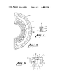
- FIG. 2 is an enlarged view of a portion of the torch assembly, a portion of the collapsing device and a temperature profile across a zone of heat which traverses the tube;
- FIG. 3 is a side elevational view of a surface mix torch assembly which includes a plurality of nozzles
- FIG. 4 is an end view of the torch assembly of FIG. 3 taken along lines 4--4;
- FIG. 5 is an elevational view in section of the torch assembly shown in FIG. 4 and taken along lines 5--5 thereof;
- FIG. 6 is a detail view of a portion of the torch assembly shown in FIG. 3 and taken along lines 6--6 thereof;
- FIG. 7 is an end view of a portion of the torch assembly of FIG. 3 along lines 7--7 thereof;
- FIG. 8 is a front elevational view of a tailstock end of a lathe and an exhaust tube
- FIG. 9 is a front elevational view of an alternative embodiment of an exhaust tube retainer at the tailstock end of the glass tube.
- FIG. 10 is a perspective view of a lathe on which a preform tube is made and which includes a plurality of switches for controlling the operation of the collapsing device.
- FIG. 1 there is shown an apparatus, designated generally by the numeral 30, for heating and collpasing a glass tube 31 to manufacture a solid silica glass preform from which a lightguide fiber is drawn.
- a substrate tube 31 is heated in order to cause the reaction products of gases and/or dopants being fed into the tube to be fused to the inside wall thereof to provide a preform tube having an optically suitable profile for communications use.
- the numeral 31 is used to designate both the substrate tube and the preform tube.
- the heating of the glass tube 31 is carried out while gas phase reactants are delivered to the tube.
- a system for this delivery is disclosed in U.S. Pat. No. 4,276,243 which issued on June 30, 1981, in the name of F. P. Partus.
- the apparatus 30 generally comprises a lathe 32 having a headstock 33 and a tailstock 34 which are used to support the glass starting tube 31 for rotation about its longitudinal axis 36 (see FIG. 2).
- the lathe 32 also includes a carriage 40 which is mounted for reciprocal movement along the lathe. Mounted on the carriage 40 is a torch assembly which is designated generally by the numeral 50 and a collapsing device which is designated 51.
- the torch assembly 50 is adapted to cause a flow of combustible gases to produce flames which are directed toward the tube 31.
- the torch assembly 50 establishes a zone of heat 54 (see FIG. 2) having a temperature profile 55 at the surface of the tube.
- the mounting of the torch assembly 50 on the carriage 40 and its movement relative to the tube 31 causes the zone of heat, which is referred to as a hot zone, to be moved along the length of the tube.
- the torch assembly 50 includes a housing 52 supported by a bracket 53 which is supported from a post 56 that is mounted on the carriage 40.
- the torch assembly 50 may be moved within any one of a range of distances from the tube 31 or to any one of a plurality of positions about and spaced from the tube.
- the capability of adjusting the torch relative to the tube 31 in a transverse direction aids in the control of the temperature profile along successive portions of the tube as the torch assembly moves along the length of the rotating tube during a deposition mode.
- the housing 52 of the torch assembly 50 includes a center section 62 which is disposed between two cover plates 63a-63b.
- a plurality of radially disposed gas nozzles 68--68 extend through and are supported by a bridge wall 67.
- Each includes a passageway 71 (see FIG. 7).
- Each of the cover plates 63a-63b includes a semi-annular lip 74 (see FIG. 6) which extends toward the nozzles 68--68 so that the nozzles are clamped effectively between the opposing lips. Openings 77--77 (see again FIG. 7) are formed between the ends of the nozzles and between the ends of the nozzles and the lips 74--74.
- the housing 52 includes a plurality of tunnels 78--78 which communicate with a supply hydrogen gas and a plurality of tunnels 79--79 that are connected externally to a supply of oxygen gas.
- the cover plates 63a-63b When assembled as shown in FIGS. 3 and 6, the cover plates 63a-63b cooperate with the center section 62 to form an outer cavity 80 and an inner cavity 81.
- the outer cavity 80 opens to the tunnels 79--79 so that the supply of oxygen flows into the cavity 80 and then into the nozzles 68--68.
- the cavity 81 communicates with the tunnels 78--78 so that hydrogen flows into the cavity 81 and thence outwardly through the openings 77--77.
- the bridge wall 67 functions to separate the two cavities 80 and 81 and to prevent any interaction between the two combustible gases.
- the oxygen and the hydrogen are moved through and about the nozzles 68--68 and are mixed generally along an arcuate surface 82 (see FIGS. 3-4) to produce flames which impinge on the tube 31.
- the distance between the tube 31 and the arcuate surface 82 of the torch assembly 50 to which the nozzles 68--68 open is generally in the range of about 1.8-2.0 cm. This distance may vary as between the deposition and collapse modes of the preform manufacture.
- the flows which are emitted to the surface 82 result in flames which provide a temperature profile that facilitates the deposition of doped silicon dioxide, for example, on the inner surface of the tube 31 and collapse.
- the torch assembly 50 produces a zone of heat 54 (see FIG. 2) with temperatures ranging about 1600° C. during deposition to over 2000° C. during a collapse mode.
- the zone of heat 54 is a length of the tube 31 along which the temperature profile is formed by the torch assembly 50 as it passes along the tube. As can be seen in FIG. 2, the zone of heat 54 extends ahead of the torch assembly 50 and behind it. Because the torch assembly 50 moves along the tube 31, a maximum temperature 86 within the zone of heat trails a centerline 87 of the torch assembly 50. Accordingly, the zone of heat is said to trail the torch assembly. Assuming that no adjustment to gas flow controllers is made, the faster the torch assembly is moved, the greater the distance between the maximum temperature 86 of the heat zone and the centerline 87 of the torch assembly.
- a coolant such as water, for example, is fed into each of two conduits 93--93 (see FIGS. 3 and 4) and directed through semi-annular channels 94--94 (see also FIG. 6). From the channels 94--94, the coolant moves into exit conduits 96--96 and out of the assembly 50 for recirculation.
- the apparatus 30 includes facilities for collapsing the preform tube following deposition by either the MCVD or the plasma MCVD process, for example.
- the methods and apparatus of this invention decrease substantially the time required to collapse the tube 31.
- the velocity of the torch achieved by the methods of this invention is about twice that used during the prior art technique of collapse by surface tension. As a result, collapse time is reduced by about 50%.
- a tube contact device 101 is positioned adjacent to the torch assembly 50. It is adapted to be moved in tandem with the torch assembly 50 in a number of passes along the length of the preform tube.
- the contact device 101 may be displaced from the torch assembly 50 in a circumferential direction about the tube.
- the contact device 101 includes a roller 102 which is made of graphite.
- the roller 102 is mounted rotatably in bearings 104--104 that are supported in a platform 106.
- the contact device may take other forms such as, for example, a metallic or ceramic tube or a non-rotatable graphite block.
- the contact device 101 is mounted on the carriage 40, but could just as well be supported from the torch assembly 50 or from an arm 107 of the torch bracket 53. Further, it is positioned on the trailing side of the torch assembly 50 as defined in a collapse mode, and in an operated position in the preferred embodiment, is adjacent to the underside of the glass tube 31 which is destined to become the preform.
- Parameters which are important to the forced collapse of the tube are the temperature of the glass within the zone of heat, the carriage speed and the position of the engagement of the roller 102 with the tube 31 relative to the zone of heat 54.
- the zone of heat is formed in the vicinity of the torch assembly as the torch passes along the tube 31, but, as will be recalled, it is usually not centered with respect to the centerline of the torch and trails it (see FIG. 2).
- the distance by which its maximum temperature 86 lags the torch assembly is a function of the velocity of the torch assembly; the greater the velocity, the greater the trailing distance.
- the maximum velocity at which the torch assembly can be moved and still provide sufficient heat to the tube to facilitate a forced collapse is dependent on and limited by the efficiency of the torch.
- the distance is also a function of the diameter of the tube 31 and its thickness.
- the maximum temperature 86 of the hot zone occurs at the torch centerline 87. Inasmuch as the tube 31 has a thickness and the torch assembly 50 is moving along the tube, the hot zone lags the torch assembly.
- the contact device 101 must engage the glass tube 31 at a point where the glass can be moved in on itself, Inasmuch as the location of the hot zone is difficult to ascertain, the roller 102 may be referenced to the centerline 87 of the torch assembly 50.
- a distance d 1 (see FIG. 2) between the centerline 87 of the torch assembly 50 and the center axis 108 of the roller 102 is called the trailing distance and occurs where the increment of length of glass is soft enough to be collapsed without fracturing or surface stressing the tube 31 or deposited core.
- the distance d 1 is on the order of 4.0 cm. Should the distance exceed an established range, the glass which is contacted by the roller 102 would be too cool to be collapsed successfully. Excessive amounts of burner gas may have to be used to compensate for the excessive spacing of the torch assembly 50 and the roller 102.
- the distance d 1 is somewhat greater than that used to position the contact device for a straightening mode, such as is disclosed in copending application Ser. No. 388,561, filed June 12, 1982 in the names of B. Lynch and F. P. Partus.
- a straightening mode such as is disclosed in copending application Ser. No. 388,561, filed June 12, 1982 in the names of B. Lynch and F. P. Partus.
- the platform 106 is mounted for vertical movement.
- the vertical movement may be provided by a rack and pinion arrangement, a helical gear arrangement or a bevel gear arrangement as shown in FIG. 1, or other equivalent mechanism.
- a shaft 109 extends horizontally through a base 110 and has a beveled gear 111 attached to an inner end.
- the beveled gear 111 meshes with another beveled gear 112 which is attached to a lower end of a threaded shaft 113.
- the shaft 113 turns through a threaded bore of the platform 106 that supports the contact device 101.
- Two guide rods 115--115 extend vertically from the base 110 through bores in the platform 106. Rotation of the beveled gear 111 turns the beveled gear 112 which turns the threaded shaft 113. As the shaft 113 turns, the platform 106 is caused to be moved upwardly or downwardly therealong.
- Roller 102 Vertical movement of the platform 106 and hence of the roller 102 may be controlled manually through a turnwheel (not shown) attached to an outer end of the shaft 109 or by a stepping motor 117 controlled through a feedback loop (not shown). In either arrangement, the roller 102 may be moved closer to the longitudinal axis 36 of the tube between predetermined passes such as, for example, successive passes.
- the collapsing device 51 of the apparatus 30 includes facilities for causing the surface that engages the tube 31 to have a temperature that is substantially below that of the preform tube.
- the platform 106 is adapted to hold a coolant such as deionized water which may be supplied by tubes 116--116 (see FIG, 1).
- the water is applied over the surface of the roller 102 to clean the surface of the roller, which engages the tube 31.
- the water drains from the housing through a passageway (not shown) in the platform 106.
- the roller 102 is surface-cooled, it has been found that a contact device which is cooled internally, for example, also can be used to collapse the preform tube.
- a glass tube 31 is positioned in the lathe with one of its ends in the headstock 33 and with its other end connected by a welded joint 118 (see FIG. 1) to an exhaust conduit 119.
- the exhaust conduit 119 is supported in the tailstock 34 of the lathe 32.
- the glass tube 31 is rotated as the torch assembly 50 is moved in a plurality of passes of a profiled velocity in a direction from the headstock 33 to the tailstock 34. During each pass, doped reactants are moved into the tube 31 from its headstock end while spent gases are exhausted at the tailstock end.
- U.S. Pat. No. 4,278,459 which issued on July 14, 1981 in the name of F. P. Partus.
- the wall of the substrate tube which is now referred to as a preform tube is pinched adjacent to its tailstock end. This prevents the entry of moisture and other contaminants into the tube 31 while it is being collapsed.
- the doped glass tube 31 is collapsed into a solid preform preparatory to drawing.
- the lathe 32 which is used during deposition is used during collapse to support the tube 31; however, the tube could be supported by other apparatus and could be oriented vertically.
- heating, at a higher temperature than during deposition occurs as the torch assembly 50 is moved at another profiled velocity in a number of passes in a direction from the tailstock 34 to the headstock 33.
- the carriage 40 is returned rapidly to the tailstock 34 for the beginning of another cycle.
- the direction of travel of the torch assembly 50 during the collapse mode in the preferred embodiment is opposite to that in the deposition mode, it may be the same. In that event, the tube 31 is not pinched off completely at the tailstock end in order to allow for the removal of gases. Otherwise, an undesirable pressure build-up in the tube could occur.
- the graphite support roller 102 Prior to or during the first pass of the collapse mode, the graphite support roller 102 is moved upwardly to contact the rotating glass tube 31 and to apply forces thereto. As explained hereinbefore, this may be done manually or automatically. Its vertical position is a function of the tube diameter and of the velocity of the torch. The roller is pushed into the softened glass within the moving zone of heat as occurs at a predetermined distance behind the centerline 87 of the torch assembly 50. If necessary, the contact device 101 is effective to force the glass tube 31 into alignment with the centerline between the headstock 33 and the tailstock 34. Accordingly, the roller 102 is adapted to urge each successive increment of length of the tube 31 upwardly until it is disposed substantially concentrically about the centerline between the chucks of the lathe 32.
- the roller 102 is moved farther inward toward the longitudinal axis 36 of the tube 31.
- the carriage 40 is caused to be returned to the tailstock and the roller 102 caused to be moved farther toward the longitudinal axis 36 of the preform tube.
- this incremental movement of the roller 102 is repeated at the beginning of each successive pass of a plurality of passes during the collapse mode.
- the roller on each successive pass is disposed closer to the longitudinal axis 36 of the preform tube 31 than on each preceding pass.
- the collapse mode may include additional passes during which the roller 102 is not used to apply collapsing forces to the preform tube 31.
- a bead 121 is formed on the exhaust conduit 119 adjacent to an outer side 122 of the chuck of the tailstock 34.
- a clamp 124 is positioned about the exhaust conduit 119 adjacent to the outer side 122 of the tailstock chuck.
- each increment engaged by the roller 102 must be cool enough afterwards to retain its reconfiguration as the graphite roller 102 moves on to the next successive increment along the length of the tube.
- the water which is flowed over the graphite roller 102 provides a moving cold zone which helps to establish a set in the tube which is being collapsed incrementally.
- the water cooling of the roller 102 also is helpful in preventing the roller from adhering to the glass tube 31. Further, the water is effective to flush and remove glass ablations, which are caused by heating the tube 31 at a relatively high temperature, from the surface of the graphite roller. Otherwise, the abaltions would accumulate and could become deposited on the graphite roller surface and eventually transferred and impressed into the glass by the roller, resulting in stress points in the preform tube and subsequent low strength fiber.
- a controlled positive pressure inside the tube 31 is of assistance in maintaining circularity as the tube is collapsed.
- This positive pressure is constant and is less than a predetermined value to avoid causing damange to the tube, particularly where the temperature of the outside surface of the tube 31 is a maximum. This is helpful in preventing the tube 31 from going flat or oval in the softened zone of the glass adjacent to the roller 102.
- the tailstock end of the tube 31 is pinched off in a preferred embodiment prior to collapse to prevent the entry of contaminants. Although this is not necessary, it is helpful in maintaining the positive pressure inside the tube 31 to prevent the formation of any irregularities in the tube at the point of its engagement by the contact device 101.
- the preform tube includes deposited layers of chemicals throughout most of its length
- high temperatures must be used to collapse the tube because of its modified wall thickness.
- the temperature exceeds about 2000° C. which is substantially higher than the temperature of the outer surface of the substrate tube during sintering following deposition.
- the same temperature at the same torch velocity may cause the tube to sag slightly and cause an offset when the graphite support is lowered.
- a programmed delay has been incorporated into the carriage return pass after the torch oxygen has been vented. This allows the surface of the tube 31 to cool sufficiently while it is still supported by the roller 102, after which the contact device 101 is lowered for the return pass.
- the torch velocity may be ramped up as the torch approaches the ends.
- the carriage 40 begins its travel from the tailstock 34 and an actuating finger 131 is disengaged from a limit switch 132 (see FIG. 10). As a longer actuating finger 133 of the carriage becomes disengaged from a second limit switch 134, it is deactivated, causing the roller 102 to be raised to a programmed height to engage the tube 31. Then the carriage 40 is caused to traverse the length of the tube 31. At the end of that travel, an actuating finger 135 of the carriage engages a limit switch 136 whereupon the carriage travel is discontinued and the contact roller 102 remains in engagement with the tube during a so-called "cool down" period.
- the roller 102 is caused to be lowered to a datum height whereupon an interlock limit switch 137 is activated by a finger 138 of the platform 106. This causes a high speed return of the carriage 40 to the tailstock 34 whereupon the actuating finger 131 engages the limit switch 132 to cause the movement of the carriage to be reversed and another cycle of the collapse mode to begin. On the next cycle or on predetermined subsequent cycles, the roller 102 is caused to be moved incrementally closer to the longitudinal axis 36 of the tube 31.
- the engagement of the roller 102 with the tube 31 causes an impression on the outer surface of the tube.
- This slight impression generally takes the form of a scroll, the pitch of which is directly influenced by the rotational speed of the substrate tube and the velocity of the carriage 40.
- the preform is flame-polished to remove any such contaminating marks on the outer surface.
- a substrate tube from which multimode fiber was drawn had an inner diameter of 19 mm and an outer diameter of 25 mm. Following deposition, the inner diameter of the preform tube was about 17.7 mm and following collapse, the outer diameter became about 18 mm. No diminution of strength properties has been found to occur in lightguide fiber drawn from preforms which have been collapsed in accordance with the methods and apparatus of this invention.
Abstract
Description
Claims (26)
Priority Applications (1)
| Application Number | Priority Date | Filing Date | Title |
|---|---|---|---|
| US06/559,603 US4486214A (en) | 1983-12-08 | 1983-12-08 | Methods of and apparatus for collapsing a preform tube into a preform from which lightguide fiber is drawn |
Applications Claiming Priority (1)
| Application Number | Priority Date | Filing Date | Title |
|---|---|---|---|
| US06/559,603 US4486214A (en) | 1983-12-08 | 1983-12-08 | Methods of and apparatus for collapsing a preform tube into a preform from which lightguide fiber is drawn |
Publications (1)
| Publication Number | Publication Date |
|---|---|
| US4486214A true US4486214A (en) | 1984-12-04 |
Family
ID=24234231
Family Applications (1)
| Application Number | Title | Priority Date | Filing Date |
|---|---|---|---|
| US06/559,603 Expired - Lifetime US4486214A (en) | 1983-12-08 | 1983-12-08 | Methods of and apparatus for collapsing a preform tube into a preform from which lightguide fiber is drawn |
Country Status (1)
| Country | Link |
|---|---|
| US (1) | US4486214A (en) |
Cited By (15)
| Publication number | Priority date | Publication date | Assignee | Title |
|---|---|---|---|---|
| US4601740A (en) * | 1984-12-18 | 1986-07-22 | At&T Technologies, Inc. | Methods of and apparatus for at least partially closing an end portion of an optical preform tube |
| US4636236A (en) * | 1984-05-26 | 1987-01-13 | Aeg-Telefunken Kabelwerke Ag, Rheydt | Method for producing a preform for drawing optical fibers |
| US4636235A (en) * | 1984-05-26 | 1987-01-13 | Aeg-Telefunken Kabelwerke Ag, Rheydt | Method for producing optical fibers |
| US4741747A (en) * | 1984-12-12 | 1988-05-03 | U.S. Philips Corporation | Method of fabricating optical fibers |
| EP0266763A2 (en) * | 1986-11-07 | 1988-05-11 | AT&T Corp. | Methods of and apparatus for adjusting the configuration of optical substrates |
| US4875916A (en) * | 1986-11-07 | 1989-10-24 | American Telephone And Telegraph Company, At&T Technologies, Inc. | Methods of adjusting the configuration of optical substrates |
| US5030266A (en) * | 1986-11-07 | 1991-07-09 | At&T Bell Laboratories | Apparatus for adjusting the configuration of optical substrates |
| US5118333A (en) * | 1986-11-07 | 1992-06-02 | At&T Bell Laboratories | Apparatus for contacting a preform rod to cause the preform rod to have a substantially straight longitudinal axis and a transverse cross section which is substantially circular and disposed concentrically about its longitudinal axis |
| US5169422A (en) * | 1991-04-11 | 1992-12-08 | At&T Bell Laboratories | Methods for heating elongated glass substrate |
| US5188648A (en) * | 1985-07-20 | 1993-02-23 | U.S. Philips Corp. | Method of manufacturing optical fibres |
| US5522003A (en) * | 1993-03-02 | 1996-05-28 | Ward; Robert M. | Glass preform with deep radial gradient layer and method of manufacturing same |
| EP1106583A2 (en) * | 1999-12-10 | 2001-06-13 | SAMSUNG ELECTRONICS Co. Ltd. | Burner and apparatus for over-cladding a rod pre-form with a tube for optical fibres |
| US20070125127A1 (en) * | 2003-05-05 | 2007-06-07 | Fitel Usa Corp. | Methods for modifying ovality of optical fiber preforms |
| DE102017115397A1 (en) * | 2017-07-10 | 2019-01-10 | Schott Schweiz Ag | Hot forming tool for the manufacture of glass containers |
| CN117003482A (en) * | 2023-10-08 | 2023-11-07 | 成都泰盟软件有限公司 | Vertical drawing instrument for multi-step drawing |
Citations (3)
| Publication number | Priority date | Publication date | Assignee | Title |
|---|---|---|---|---|
| US4087266A (en) * | 1976-04-06 | 1978-05-02 | International Standard Electric Corporation | Optical fibre manufacture |
| US4121919A (en) * | 1977-02-18 | 1978-10-24 | Compagnie Generale D'electricite | Method of producing an optical fibre blank |
| US4302230A (en) * | 1980-04-25 | 1981-11-24 | Bell Telephone Laboratories, Incorporated | High rate optical fiber fabrication process using thermophoretically enhanced particle deposition |
-
1983
- 1983-12-08 US US06/559,603 patent/US4486214A/en not_active Expired - Lifetime
Patent Citations (3)
| Publication number | Priority date | Publication date | Assignee | Title |
|---|---|---|---|---|
| US4087266A (en) * | 1976-04-06 | 1978-05-02 | International Standard Electric Corporation | Optical fibre manufacture |
| US4121919A (en) * | 1977-02-18 | 1978-10-24 | Compagnie Generale D'electricite | Method of producing an optical fibre blank |
| US4302230A (en) * | 1980-04-25 | 1981-11-24 | Bell Telephone Laboratories, Incorporated | High rate optical fiber fabrication process using thermophoretically enhanced particle deposition |
Cited By (23)
| Publication number | Priority date | Publication date | Assignee | Title |
|---|---|---|---|---|
| US4636236A (en) * | 1984-05-26 | 1987-01-13 | Aeg-Telefunken Kabelwerke Ag, Rheydt | Method for producing a preform for drawing optical fibers |
| US4636235A (en) * | 1984-05-26 | 1987-01-13 | Aeg-Telefunken Kabelwerke Ag, Rheydt | Method for producing optical fibers |
| US4741747A (en) * | 1984-12-12 | 1988-05-03 | U.S. Philips Corporation | Method of fabricating optical fibers |
| US4601740A (en) * | 1984-12-18 | 1986-07-22 | At&T Technologies, Inc. | Methods of and apparatus for at least partially closing an end portion of an optical preform tube |
| US5188648A (en) * | 1985-07-20 | 1993-02-23 | U.S. Philips Corp. | Method of manufacturing optical fibres |
| US4875916A (en) * | 1986-11-07 | 1989-10-24 | American Telephone And Telegraph Company, At&T Technologies, Inc. | Methods of adjusting the configuration of optical substrates |
| EP0266763A3 (en) * | 1986-11-07 | 1989-10-25 | American Telephone And Telegraph Company | Methods of and apparatus for adjusting the configuration of optical substrates |
| US5030266A (en) * | 1986-11-07 | 1991-07-09 | At&T Bell Laboratories | Apparatus for adjusting the configuration of optical substrates |
| US5118333A (en) * | 1986-11-07 | 1992-06-02 | At&T Bell Laboratories | Apparatus for contacting a preform rod to cause the preform rod to have a substantially straight longitudinal axis and a transverse cross section which is substantially circular and disposed concentrically about its longitudinal axis |
| EP0266763A2 (en) * | 1986-11-07 | 1988-05-11 | AT&T Corp. | Methods of and apparatus for adjusting the configuration of optical substrates |
| US5169422A (en) * | 1991-04-11 | 1992-12-08 | At&T Bell Laboratories | Methods for heating elongated glass substrate |
| US5522003A (en) * | 1993-03-02 | 1996-05-28 | Ward; Robert M. | Glass preform with deep radial gradient layer and method of manufacturing same |
| US5673353A (en) * | 1993-03-02 | 1997-09-30 | Ward; Robert M. | Fiber and lens preform with deep radial gradient layer and method of manufacturing same |
| EP1106583A3 (en) * | 1999-12-10 | 2002-06-19 | SAMSUNG ELECTRONICS Co. Ltd. | Burner and apparatus for over-cladding a rod pre-form with a tube for optical fibres |
| EP1106583A2 (en) * | 1999-12-10 | 2001-06-13 | SAMSUNG ELECTRONICS Co. Ltd. | Burner and apparatus for over-cladding a rod pre-form with a tube for optical fibres |
| US6729163B2 (en) | 1999-12-10 | 2004-05-04 | Samsung Electronics Co., Ltd. | Apparatus for over-cladding large diameter optical fiber pre-form using the same |
| US20070125127A1 (en) * | 2003-05-05 | 2007-06-07 | Fitel Usa Corp. | Methods for modifying ovality of optical fiber preforms |
| US20110056245A1 (en) * | 2003-05-05 | 2011-03-10 | Fitel Usa Corp. | Methods for modifying ovality of optical fiber preforms |
| US7946133B2 (en) | 2003-05-05 | 2011-05-24 | Fitel Usa Corp. | Methods for modifying ovality of optical fiber preforms |
| DE102017115397A1 (en) * | 2017-07-10 | 2019-01-10 | Schott Schweiz Ag | Hot forming tool for the manufacture of glass containers |
| US11565963B2 (en) | 2017-07-10 | 2023-01-31 | Schott Pharma Schweiz Ag | Hot-forming tool for producing glass containers |
| CN117003482A (en) * | 2023-10-08 | 2023-11-07 | 成都泰盟软件有限公司 | Vertical drawing instrument for multi-step drawing |
| CN117003482B (en) * | 2023-10-08 | 2023-12-19 | 成都泰盟软件有限公司 | Vertical drawing instrument for multi-step drawing |
Similar Documents
| Publication | Publication Date | Title |
|---|---|---|
| EP0111545B1 (en) | Methods of and apparatus for straightening and configuring a preform tube from which lightguide fiber is drawn | |
| US4486214A (en) | Methods of and apparatus for collapsing a preform tube into a preform from which lightguide fiber is drawn | |
| EP1001912B1 (en) | Apparatus and method for overcladding optical fiber preform rod and optical fiber drawing method | |
| EP0082642B1 (en) | Method and apparatus for producing tubular glass article | |
| US6938442B1 (en) | Method for elongating a cylinder of silica glass | |
| KR20000011715A (en) | Large MCVD preform for singlemode fiber and method for making same | |
| JP3353912B2 (en) | Method and apparatus for manufacturing optical fiber preforms | |
| RU2235071C2 (en) | Method for preparing optical fiber blank | |
| US4576622A (en) | Manufacture of preforms for energy transmitting fibers | |
| EP0508677B1 (en) | Methods of and apparatus for heating elongated glass substrate | |
| US6220060B1 (en) | Optical fiber manufacture | |
| US5174803A (en) | Apparatus for heating glassy tubes | |
| EP0357341B1 (en) | Methods of and apparatus for heating glassy tubes | |
| KR950014692B1 (en) | Apparatus for adjusting the configuration of optical substrages | |
| US5203691A (en) | Torch assembly for heating glassy tubes | |
| US5090978A (en) | Methods of collapsing glass tube | |
| US5030266A (en) | Apparatus for adjusting the configuration of optical substrates | |
| US4601740A (en) | Methods of and apparatus for at least partially closing an end portion of an optical preform tube | |
| US4875916A (en) | Methods of adjusting the configuration of optical substrates | |
| EP0112549B1 (en) | Improved sintering of optical fiber preforms | |
| KR20000013544A (en) | Apparatus and method for fabricating freeform for high quality optical fiber | |
| US4457770A (en) | Method and apparatus for the production of optical fibers with lateral gaseous injection | |
| GB2063724A (en) | Continuous production of very small diameter metal wire | |
| KR100619342B1 (en) | Method of manufacturing optical fiber in mcvd | |
| CN111770903A (en) | Device for impact orientation of tubular preform of optical fiber body |
Legal Events
| Date | Code | Title | Description |
|---|---|---|---|
| AS | Assignment |
Owner name: WESTERN ELECTRIC COMPANY, INCORPORATED 222 BROADWA Free format text: ASSIGNMENT OF ASSIGNORS INTEREST.;ASSIGNORS:LYNCH, BRIAN;PARTUS, FRED P.;REEL/FRAME:004213/0203 Effective date: 19831207 Owner name: BELL TELEPHONE LABORATORIES, INCORPORATED 600 MOUN Free format text: ASSIGNMENT OF ASSIGNORS INTEREST.;ASSIGNORS:MACCHESNEY, JOHN B.;SIMPSON, JAY R.;REEL/FRAME:004213/0206 Effective date: 19831207 |
|
| AS | Assignment |
Owner name: AT & T TECHNOLOGIES, INC., Free format text: CHANGE OF NAME;ASSIGNOR:WESTERN ELECTRIC COMPANY, INCORPORATED;REEL/FRAME:004251/0868 Effective date: 19831229 |
|
| STCF | Information on status: patent grant |
Free format text: PATENTED CASE |
|
| FEPP | Fee payment procedure |
Free format text: PAYOR NUMBER ASSIGNED (ORIGINAL EVENT CODE: ASPN); ENTITY STATUS OF PATENT OWNER: LARGE ENTITY |
|
| FPAY | Fee payment |
Year of fee payment: 4 |
|
| FPAY | Fee payment |
Year of fee payment: 8 |
|
| FPAY | Fee payment |
Year of fee payment: 12 |
|
| AS | Assignment |
Owner name: LUCENT TECHNOLOGIES INC., NEW JERSEY Free format text: ASSIGNMENT OF ASSIGNORS INTEREST;ASSIGNOR:AT&T CORP.;REEL/FRAME:012059/0893 Effective date: 19960329 |
|
| AS | Assignment |
Owner name: FITEL USA CORPORATION, GEORGIA Free format text: ASSIGNMENT OF ASSIGNORS INTEREST;ASSIGNOR:LUCENT TECHNOLOGIES;REEL/FRAME:012946/0578 Effective date: 20011116 |