US4489897A - Apparatus for shredding documents - Google Patents
Apparatus for shredding documents Download PDFInfo
- Publication number
- US4489897A US4489897A US06/471,309 US47130983A US4489897A US 4489897 A US4489897 A US 4489897A US 47130983 A US47130983 A US 47130983A US 4489897 A US4489897 A US 4489897A
- Authority
- US
- United States
- Prior art keywords
- members
- yoke
- rotatable
- portions
- cylindrical
- Prior art date
- Legal status (The legal status is an assumption and is not a legal conclusion. Google has not performed a legal analysis and makes no representation as to the accuracy of the status listed.)
- Expired - Fee Related
Links
Images

Classifications
-
- B—PERFORMING OPERATIONS; TRANSPORTING
- B02—CRUSHING, PULVERISING, OR DISINTEGRATING; PREPARATORY TREATMENT OF GRAIN FOR MILLING
- B02C—CRUSHING, PULVERISING, OR DISINTEGRATING IN GENERAL; MILLING GRAIN
- B02C18/00—Disintegrating by knives or other cutting or tearing members which chop material into fragments
- B02C18/0007—Disintegrating by knives or other cutting or tearing members which chop material into fragments specially adapted for disintegrating documents
- B02C2018/0069—Disintegrating by knives or other cutting or tearing members which chop material into fragments specially adapted for disintegrating documents with stripping devices
-
- B—PERFORMING OPERATIONS; TRANSPORTING
- B02—CRUSHING, PULVERISING, OR DISINTEGRATING; PREPARATORY TREATMENT OF GRAIN FOR MILLING
- B02C—CRUSHING, PULVERISING, OR DISINTEGRATING IN GENERAL; MILLING GRAIN
- B02C18/00—Disintegrating by knives or other cutting or tearing members which chop material into fragments
- B02C18/06—Disintegrating by knives or other cutting or tearing members which chop material into fragments with rotating knives
- B02C18/16—Details
- B02C2018/164—Prevention of jamming and/or overload
Definitions
- the present invention is directed to an improved device for shredding documents which device has two rotating members having a plurality of knife-like cylindrical members that are interdigitally mounted to shred a document as it passes therebetween.
- shredding In order to destroy documents to preserve their confidentiality, it is known to cut the documents in narrow strips in a process which is commonly referred to as shredding.
- a specific way of shredding is achieved with circular knives or cutters which are arranged along an axis of a rotating member and coact with a second member having similar knives which are offset so that the knives of one member pass between the rotating knives of the other member.
- stripping arrangements are positioned between the rotating knives on each of the two rotating members to insure that the shredded material does not stick.
- the actual structure of the rotating members having knives or cutters can be a solid bar of steel or similar material in which the knives and cutters are formed by machining so that the cutter and the spacer are all integral to one another.
- Another structure has separate cylindrical members of a large diameter which are utilized as the knives or cutters and are spaced apart by separate cylindrical spacers which are assembled on a shaft in an alternating relationship.
- a third structure is a plurality of sleeves having integral knives and spacers, which sleeves are then assembled on shafts to form the rotating members.
- the shredding device also has strippers or paper guides which are utilized and extend in the area of the spacer for the purpose of guiding the material into the two rotating members or cutting rolls and also to lead the shredded material out on the discharge side as severed or cut strips.
- the present invention is directed to an improved shredding device which overcomes problems of jamming known in the prior art devices without increasing the diameter of the shafts or rotating members and thus maintaining manufacturing costs to a minimum without losing the function or sales appeal of the device.
- the present invention is directed to an apparatus for shredding paper comprising a frame, a pair of rotatable members, each member having a plurality of first cylindrical portions such as cylindrical cutters and a plurality of second cylindrical portions such as cylindrical spacers alternately arranged along the axis of each of the members with the first cylindrical portions or cutters being of a larger diameter than the second cylindrical portions or spacers to provide annular spaces adjacent the periphery of each second portion and between adjacent first cylindrical portions, means for mounting the pair of members interdigitally in the frame for rotation with the first cylindrical portions or cutters of one of the pair of members being opposite the second portions of the other member of the pair and extending into the annular spaces associated therewith so that the first cylindrical portions or cutters of the pair of rotating members overlap each other and coact to shred material passing between the pair of rotating members, means for rotating said pair of members, stripping means operatively extending into the annular spaces between said rotating members to aid in guiding material to pass between said pair of rotating members and to strip or remove material
- each of the yoke members comprises a transverse support member which extends substantially parallel to the rotating members. If each rotating member is provided with the backup means, each rotating member has a support member. While each of the yoke members may have only a single finger preferably, they are provided with more than one finger so that they will engage either adjacent second cylindrical portions or closely spaced second cylindrical portions. Preferably, at least two yoke members are utilized for each rotating member.
- the yoke member can also be formed of a self-lubricating sintered bronze powder metal alloy to insure long life and to enable mounting of the yoke member to be in sliding engagement with the second portion.
- FIG. 1 is a schematic illustration of a shredding device or apparatus in accordance with the present invention
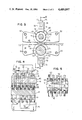
- FIG. 2 is a view of the shredding members taken approximately along lines II--II of FIG. 1;
- FIG. 3 is a cross-sectional view taken along lines III--III of FIG. 2;
- FIG. 4 is a cross-sectional view taken along lines IV--IV of FIG. 3;
- FIG. 5 is a view taken along lines V--V of FIG. 4;
- FIG. 6 is a perspective view of a yoke member in accordance with the present invention.
- FIG. 7 is a perspective view of an embodiment of the yoke member of the present invention.
- the principles of the present invention are particularly useful when incorporated in a shredding apparatus or device generally indicated at 10 in FIG. 1.
- the shredding apparatus 10 has a housing or frame 9 which contains two shredding rolls or rotatable members 11 and 12, and means 13 for mounting the two rolls 11 and 12 interdigitally for rotation in the frame or housing 9.
- a drive means including an electric motor 15 is provided to drive the rotatable members 11 and 12.
- the controls for the electric motors include in addition to start and stop switches, an automatic reversing system for the shredder generally indicated by a box 16 which as mentioned above is disclosed and claimed in copending U.S. patent application Ser. No. 422,282, whose disclosure is incorporated herein by reference thereto.
- the controls also include a sensing means 17 which senses the level of material in a hopper or bag 18 that receives the shredded material.
- the drive means as mentioned hereinabove include the electric motor 15 whose output is connected by a belt 21 to a pulley 22 (FIG. 2) which is keyed on a shaft 23 of the rotatable member 11.
- a gear connection such as a pinion gear 24 is keyed on the shaft 23 and engages a pinion gear 25 on a shaft 26 of the member 12.
- documents such as 30 are introduced through a throat or slot 31 to pass between the two rotatable members 11 and 12 where they are shredded into strips and deposited in a hopper or bag 18.
- the sensing device 17 will create a signal which may be used to actuate an indicating light on the housing 11 and also may be utilized to stop the motor 15.
- the large number or thick arrangement of documents will cause a slowing-down of the system which causes the reversing control 16 to reverse the drive of the motor to expel the documents back out through the throat 31.
- the present invention will prevent jamming if there is a malfunction of the reversing system 16 or even if the reversing system is not present in the shredder 10.
- the first or upper rotatable member 11 has a plurality of first cylindrical portions or cutters 40, which are spaced apart by second cylindrical portions or spacers 41. Between two first cylindrical portions 40 and adjacent each spacer 41 an annular space 42 is formed and is radially outward of the cylindrical or peripheral surface 43 of the spacer 41 as best seen in FIG. 3.
- the lower or second rotatable member 12 has a plurality of first cylindrical members or cutters 50 and second cylindrical members or spacers 51. The spacers are interposed between the cutters 50 so that an annular space 52 will lie between two adjacent cutters 50 and radially outward from a cylindrical or peripheral surface 53 of the spacer 51.
- each of the rotating members such as the member 11 can be formed by a shaft 45 on which the plurality of cylindrical members or cutters 40 and the spacers 41 have been assembled with the spacers between adjacent cutters.
- the shaft has a noncylindrical cross-section such as a hexagon so that each of the cutters as well as the spacers will be positively driven.
- the member can be formed from a single member as illustrated by the member 12.
- the member 12 is a steel shaft which has been machined to produce the cutters 50 which are spaced from each other by smaller cylindrical diameter portions 51. It should be noted that as illustrated, each of the cutters 40 and 50 have serrated peripheral surfaces.
- the mounting means 13 mounts the two rotatable members 11 and 12 as best illustrated in FIGS. 2-4 with the first cylindrical portions 40, which have a larger diameter than the second cylindrical portions 41, lying opposite the second cylindrical portions or spacers 51 of the member 12. Also, the two members 11 and 12 are mounted so that the first portions 40 extend into the annular spaces 52 between the first cylindrical portions 50 of the member 12 while the first cylindrical portions 50 extend into the annular spaces 42 and between adjacent cylindrical members or cutters 40. This interdigital arrangement provides a cutting overlap between the cylindrical cutters 40 of the member 11 and the cylindrical cutters 50 of the member 12.
- guiding and stripping arrangements include a plurality of members 47 and 57.
- the members 47 have a cutout portion 48 so that they can be arranged in the annular space 42 with a bottom surface 49 spaced from the peripheral surface of the opposite cutter 50.
- the member 57 has a cutout portion 48 to allow it to be mounted in the annular space 52 with a bottom surface 59 extending substantially parallel to the bottom surface 49 and spaced from the peripheral surface of the cutter or first cylindrical member 40.
- each of the members 47 and 57 is formed of a sheet metal member which is bent into a U-shaped cross-section. However, they can be a single member or plate. It is also noted that each of the surfaces 49 and 50 has a tapering portion to form an incoming throat 33 and an exit throat 34.
- each of the members 11 and 12, regardless of their particular structure, is mounted by the means 13 which comprise a pair of side plates 60 and 61 which have bearings for rotatably supporting each of the members for rotation.
- the side plate 60 may have rods such as 62 and 63 which are utilized to mount the members 47 and 57 that form the stripping means as best shown in FIG. 3.
- the side plates or members 60 and 61 are detachably connected into the frame or housing 9 of the device 10.
- the backup arrangement or means includes a pair of yoke members 70 which have two spaced fingers 71 which terminate in arcuate end surfaces 72 (FIG. 3).
- the fingers 71 are spaced apart by a gap 73 which as illustrated in FIG. 4, is large enough to receive two of the first cylindrical portions 40 as well as one spacer 41.
- the backup means also include means for positioning each of the yokes 70 with the end surfaces 72 of the fingers 71 either spaced from the periphery 43 by a given amount as illustrated in FIGS.
- the means for mounting comprises a support member 75 which has a rectangular shape and is mounted on the members 60 and 61 to extend parallel to the axes of the rotating members 11 and 12. To provide the resisting force in the right direction, the axis of the support member 75 lies in a plane formed by the axes of members 11 and 12.
- Each of the yoke members 70 on a surface 76, which is opposite the surfaces 72 has a groove 77 (see FIGS. 3 and 6). The groove 77 may be selected to form a tight fit with the support member 75 so that the yoke member 70 can be slid along the support member 75 to the desired position.
- the rotating member 12 is provided with support means which also consist of a support member 75 which supports two yoke members 70 with their end surfaces 72 being spaced from a periphery 53 of the second portions 51 of the member 12.
- yoke member 70' instead of utilizing yoke members 70, an embodiment is illustrated by the yoke member 70' in FIG. 7 which embodiment has four fingers 71' each having arcuate end surfaces 72'. Adjacent fingers 71' are spaced by gap 73' which gap only has the thickness of an adjacent cutter or first cylindrical portion such as 40 or 50.
- the yoke member 70' may be an advantage over the yoke member 70 when the spacing between the cutters such as 40 and 50 is small.
- the shredding devices 10 can utilize rotatable members 11 and 12, which will cut different sizes of strips.
- the cylindrical portions 40 and 41 as well as 50 and 51 will have the substantially the same thickness and this thickness will determine the size of the shredded pieces of a document.
- they may have a thickness of approximately 2 mm, 4 mm or 6 mm.
- the yoke member 70' may be advantageously used with a device which has the smaller thickness for the cylindrical portions while the yoke member 70 would be utilized for a device which has those having the greater thickness.
- the yoke members 70 and 70' may be made of a self-lubricating material.
- the members may be made of a self-lubricating sintered bronze powder alloy.
- two yoke members 70 are sufficient with a rotating member having a length of approximately 12-13 inches. However, when increasing the length of the rotating member to approximately 19 inches, three members are preferred. It is also contemplated utilizing the backup means only for one of the two rotating members although it is illustrated as being utilized with both. Thus, the upper or first rotating member 11 may be provided with the backup means while the member 12 is not or the member 12 may be provided with the backup means while the member 11 is not or the third arrangement is both members as illustrated are provided with the backup means.
Abstract
Description
Claims (19)
Priority Applications (1)
| Application Number | Priority Date | Filing Date | Title |
|---|---|---|---|
| US06/471,309 US4489897A (en) | 1983-03-02 | 1983-03-02 | Apparatus for shredding documents |
Applications Claiming Priority (1)
| Application Number | Priority Date | Filing Date | Title |
|---|---|---|---|
| US06/471,309 US4489897A (en) | 1983-03-02 | 1983-03-02 | Apparatus for shredding documents |
Publications (1)
| Publication Number | Publication Date |
|---|---|
| US4489897A true US4489897A (en) | 1984-12-25 |
Family
ID=23871112
Family Applications (1)
| Application Number | Title | Priority Date | Filing Date |
|---|---|---|---|
| US06/471,309 Expired - Fee Related US4489897A (en) | 1983-03-02 | 1983-03-02 | Apparatus for shredding documents |
Country Status (1)
| Country | Link |
|---|---|
| US (1) | US4489897A (en) |
Cited By (49)
| Publication number | Priority date | Publication date | Assignee | Title |
|---|---|---|---|---|
| US4691871A (en) * | 1984-08-31 | 1987-09-08 | Mochizuki Precision Machine Industries Co., Ltd. | Cutting apparatus |
| US4693428A (en) * | 1984-11-01 | 1987-09-15 | Cummins Allison Corporation | Particle-type shredding mechanism |
| DE3610539A1 (en) * | 1986-03-27 | 1987-10-01 | Hermann Schwelling | Stripping unit for the pair of cutting rollers of a document shredder |
| EP0260636A2 (en) * | 1986-09-15 | 1988-03-23 | H.S.M. Pressen GmbH | Stripper for the cutting mechanism of a document shredder |
| US4889143A (en) * | 1986-05-14 | 1989-12-26 | R. J. Reynolds Tobacco Company | Cigarette rods and filters containing strands provided from sheet-like materials |
| GB2234690A (en) * | 1989-07-28 | 1991-02-13 | Ever Bright Electronics Factor | Paper shredder and letter opener |
| US4997134A (en) * | 1990-01-16 | 1991-03-05 | Group Four Design | Document shredding machine and method |
| US5071080A (en) * | 1990-02-27 | 1991-12-10 | Fellowes Manufacturing Company | Document shredding machine |
| US5232510A (en) * | 1991-01-04 | 1993-08-03 | Tilbey Sydney E | Slitting apparatus for sugarcane rind |
| US5295633A (en) * | 1992-01-13 | 1994-03-22 | Fellowes Manufacturing Company | Document shredding machine with stripper and cutting mechanism therefore |
| EP0616850A2 (en) * | 1993-03-22 | 1994-09-28 | Hermann Schwelling | Document shredder |
| US5409171A (en) * | 1991-03-22 | 1995-04-25 | Schleiche & Co. International Aktiengesellschaft | Document shredder |
| US5474243A (en) * | 1993-07-20 | 1995-12-12 | Schwelling; Herman | Stripping system of a cutting mechanism for a paper shredder |
| US5636801A (en) * | 1995-08-02 | 1997-06-10 | Fellowes Mfg. Co. | One piece molded stripper for shredders |
| US5655725A (en) * | 1995-08-24 | 1997-08-12 | Fellowes Manufacturing Co. | Retaining plate for gearing |
| US5676321A (en) * | 1995-04-03 | 1997-10-14 | Fellowes Mfg. Co. | Cutting disk |
| US5826809A (en) * | 1997-04-30 | 1998-10-27 | Fellowes Manufacturing Company | Support for cutting cylinders in a paper shredder |
| US5829697A (en) * | 1995-08-24 | 1998-11-03 | Fellowes Manufacturing Company | Support for cylinders in a paper shredder |
| US5839675A (en) * | 1996-10-02 | 1998-11-24 | General Binding Corporation | Shredder support assembly and housing |
| USD404756S (en) * | 1996-10-02 | 1999-01-26 | General Binding Corporation | Shredder |
| US5954280A (en) * | 1998-05-12 | 1999-09-21 | Fellowes Manufacturing Company | Top blocker for a paper shredder |
| US5961059A (en) * | 1997-04-30 | 1999-10-05 | Fellowes Manufacturing Company | Support for drive system in a paper shredder |
| US5988542A (en) * | 1998-05-18 | 1999-11-23 | General Binding Corporation | Document shredding devices |
| US6079645A (en) * | 1998-09-15 | 2000-06-27 | General Binding Corporation | Desktop shredders |
| US6572037B1 (en) | 1999-02-04 | 2003-06-03 | Mct Holdings, Llc | Shredder with parts ejector |
| US20060219827A1 (en) * | 2004-09-10 | 2006-10-05 | Fellowes Inc. | Shredder with thickness detector |
| US20070221767A1 (en) * | 2006-03-22 | 2007-09-27 | Fellowes, Inc. | Shredder with oiling mechanism |
| US20070246582A1 (en) * | 2006-04-24 | 2007-10-25 | Acco Uk Limited | Shredding machine |
| US20070284462A1 (en) * | 2003-10-06 | 2007-12-13 | Amos Mfg., Inc. | Shredding machine |
| US20080066322A1 (en) * | 2006-09-14 | 2008-03-20 | The Government Of The Usa As Represented By The Secretary Of The Dept. Of Health & Human Services | Dissection Tool and Methods of Use |
| US20090032629A1 (en) * | 2007-08-02 | 2009-02-05 | Acco Uk Limited | Shredding machine |
| KR100896348B1 (en) | 2007-03-08 | 2009-05-07 | 코리아유니크 주식회사 | Anti-bending devices of rotation axis paper shredding machines |
| US7641138B1 (en) * | 2008-04-14 | 2010-01-05 | Emily Lo | Auxiliary unit of paper shredder cutting tools |
| US7661614B2 (en) | 2004-09-10 | 2010-02-16 | Fellowes Inc. | Shredder throat safety system |
| US20100096484A1 (en) * | 2008-10-20 | 2010-04-22 | Michilin Prosperity Co., Ltd. | Lock elements for preventing rotary shafts of shredder from bending |
| US7954737B2 (en) | 2007-10-04 | 2011-06-07 | Fellowes, Inc. | Shredder thickness with anti-jitter feature |
| US8091809B2 (en) | 2009-03-24 | 2012-01-10 | Fellowes, Inc. | Shredder with jam proof system |
| US8201761B2 (en) | 2009-01-05 | 2012-06-19 | Fellowes, Inc. | Thickness sensor based motor controller |
| US8205815B2 (en) | 2009-05-15 | 2012-06-26 | Fellowes, Inc. | Paper alignment sensor arrangement |
| US8382019B2 (en) | 2010-05-03 | 2013-02-26 | Fellowes, Inc. | In-rush current jam proof sensor control |
| US8430347B2 (en) | 2009-01-05 | 2013-04-30 | Fellowes, Inc. | Thickness adjusted motor controller |
| US8511593B2 (en) | 2010-05-28 | 2013-08-20 | Fellowes, Inc. | Differential jam proof sensor for a shredder |
| US8550387B2 (en) | 2009-06-18 | 2013-10-08 | Tai Hoon K. Matlin | Restrictive throat mechanism for paper shredders |
| US8672247B2 (en) | 2005-07-11 | 2014-03-18 | Fellowes, Inc. | Shredder with thickness detector |
| US8678305B2 (en) | 2009-06-18 | 2014-03-25 | Fellowes, Inc. | Restrictive throat mechanism for paper shredders |
| US20140200548A1 (en) * | 2013-01-17 | 2014-07-17 | Merit Medical Systems, Inc. | Apparatuses and kits for grinding or cutting surgical foam and methods related thereto |
| US8870106B2 (en) | 2004-09-10 | 2014-10-28 | Fellowes, Inc. | Shredder with thickness detector |
| US20160136651A1 (en) * | 2014-11-17 | 2016-05-19 | National Conveyors Company, Inc. | Apparatus and methods for removing blockages in a shredding apparatus |
| KR102240929B1 (en) * | 2019-12-11 | 2021-04-16 | (주)대진코스탈 | Paper shredder blade guide adopted bending protection |
Citations (3)
| Publication number | Priority date | Publication date | Assignee | Title |
|---|---|---|---|---|
| GB1468662A (en) * | 1973-05-17 | 1977-03-30 | Improvements in or relating to crushing apparatus | |
| GB2059804A (en) * | 1979-10-16 | 1981-04-29 | Sant Andrea Novara Officine | Comminuting machine |
| US4411391A (en) * | 1980-05-27 | 1983-10-25 | Ofrex Group Limited | Document shredding machines |
-
1983
- 1983-03-02 US US06/471,309 patent/US4489897A/en not_active Expired - Fee Related
Patent Citations (3)
| Publication number | Priority date | Publication date | Assignee | Title |
|---|---|---|---|---|
| GB1468662A (en) * | 1973-05-17 | 1977-03-30 | Improvements in or relating to crushing apparatus | |
| GB2059804A (en) * | 1979-10-16 | 1981-04-29 | Sant Andrea Novara Officine | Comminuting machine |
| US4411391A (en) * | 1980-05-27 | 1983-10-25 | Ofrex Group Limited | Document shredding machines |
Cited By (79)
| Publication number | Priority date | Publication date | Assignee | Title |
|---|---|---|---|---|
| US4691871A (en) * | 1984-08-31 | 1987-09-08 | Mochizuki Precision Machine Industries Co., Ltd. | Cutting apparatus |
| US4693428A (en) * | 1984-11-01 | 1987-09-15 | Cummins Allison Corporation | Particle-type shredding mechanism |
| DE3610539A1 (en) * | 1986-03-27 | 1987-10-01 | Hermann Schwelling | Stripping unit for the pair of cutting rollers of a document shredder |
| US4889143A (en) * | 1986-05-14 | 1989-12-26 | R. J. Reynolds Tobacco Company | Cigarette rods and filters containing strands provided from sheet-like materials |
| EP0260636A2 (en) * | 1986-09-15 | 1988-03-23 | H.S.M. Pressen GmbH | Stripper for the cutting mechanism of a document shredder |
| EP0260636A3 (en) * | 1986-09-15 | 1989-05-31 | Hermann Schwelling | Stripper for the cutting mechanism of a document shredder |
| GB2234690A (en) * | 1989-07-28 | 1991-02-13 | Ever Bright Electronics Factor | Paper shredder and letter opener |
| US4997134A (en) * | 1990-01-16 | 1991-03-05 | Group Four Design | Document shredding machine and method |
| US5071080A (en) * | 1990-02-27 | 1991-12-10 | Fellowes Manufacturing Company | Document shredding machine |
| US5232510A (en) * | 1991-01-04 | 1993-08-03 | Tilbey Sydney E | Slitting apparatus for sugarcane rind |
| US5409171A (en) * | 1991-03-22 | 1995-04-25 | Schleiche & Co. International Aktiengesellschaft | Document shredder |
| US5295633A (en) * | 1992-01-13 | 1994-03-22 | Fellowes Manufacturing Company | Document shredding machine with stripper and cutting mechanism therefore |
| EP0616850A2 (en) * | 1993-03-22 | 1994-09-28 | Hermann Schwelling | Document shredder |
| EP0616850A3 (en) * | 1993-03-22 | 1995-01-25 | Hermann Schwelling | Document shredder. |
| US5474243A (en) * | 1993-07-20 | 1995-12-12 | Schwelling; Herman | Stripping system of a cutting mechanism for a paper shredder |
| US5676321A (en) * | 1995-04-03 | 1997-10-14 | Fellowes Mfg. Co. | Cutting disk |
| US5636801A (en) * | 1995-08-02 | 1997-06-10 | Fellowes Mfg. Co. | One piece molded stripper for shredders |
| US5655725A (en) * | 1995-08-24 | 1997-08-12 | Fellowes Manufacturing Co. | Retaining plate for gearing |
| US5829697A (en) * | 1995-08-24 | 1998-11-03 | Fellowes Manufacturing Company | Support for cylinders in a paper shredder |
| USD404756S (en) * | 1996-10-02 | 1999-01-26 | General Binding Corporation | Shredder |
| US5839675A (en) * | 1996-10-02 | 1998-11-24 | General Binding Corporation | Shredder support assembly and housing |
| US5826809A (en) * | 1997-04-30 | 1998-10-27 | Fellowes Manufacturing Company | Support for cutting cylinders in a paper shredder |
| US5961059A (en) * | 1997-04-30 | 1999-10-05 | Fellowes Manufacturing Company | Support for drive system in a paper shredder |
| US5954280A (en) * | 1998-05-12 | 1999-09-21 | Fellowes Manufacturing Company | Top blocker for a paper shredder |
| US5988542A (en) * | 1998-05-18 | 1999-11-23 | General Binding Corporation | Document shredding devices |
| US6079645A (en) * | 1998-09-15 | 2000-06-27 | General Binding Corporation | Desktop shredders |
| US6572037B1 (en) | 1999-02-04 | 2003-06-03 | Mct Holdings, Llc | Shredder with parts ejector |
| US7802740B2 (en) * | 2003-10-06 | 2010-09-28 | Amos Mfg., Inc. | Shredding machine |
| US20070284462A1 (en) * | 2003-10-06 | 2007-12-13 | Amos Mfg., Inc. | Shredding machine |
| US7631823B2 (en) | 2004-09-10 | 2009-12-15 | Fellowes Inc. | Shredder with thickness detector |
| US7712689B2 (en) | 2004-09-10 | 2010-05-11 | Fellowes Inc. | Shredder with thickness detector |
| US8870106B2 (en) | 2004-09-10 | 2014-10-28 | Fellowes, Inc. | Shredder with thickness detector |
| US20070246586A1 (en) * | 2004-09-10 | 2007-10-25 | Fellowes Inc. | Shredder with thickness detector |
| US8783592B2 (en) | 2004-09-10 | 2014-07-22 | Fellowes, Inc. | Shredder with thickness detector |
| US20070246580A1 (en) * | 2004-09-10 | 2007-10-25 | Fellowes Inc. | Shredder with thickness detector |
| US7963468B2 (en) | 2004-09-10 | 2011-06-21 | Fellowes, Inc. | Shredder with thickness detector |
| US7946515B2 (en) | 2004-09-10 | 2011-05-24 | Fellowes, Inc. | Shredder throat safety system |
| US7631822B2 (en) | 2004-09-10 | 2009-12-15 | Fellowes Inc. | Shredder with thickness detector |
| US7946514B2 (en) | 2004-09-10 | 2011-05-24 | Fellowes, Inc. | Shredder with thickness detector |
| US7631824B2 (en) | 2004-09-10 | 2009-12-15 | Fellowes Inc. | Shredder with thickness detector |
| US7635102B2 (en) | 2004-09-10 | 2009-12-22 | Fellowes Inc. | Shredder with thickness detector |
| US20060219827A1 (en) * | 2004-09-10 | 2006-10-05 | Fellowes Inc. | Shredder with thickness detector |
| US7661614B2 (en) | 2004-09-10 | 2010-02-16 | Fellowes Inc. | Shredder throat safety system |
| US8672247B2 (en) | 2005-07-11 | 2014-03-18 | Fellowes, Inc. | Shredder with thickness detector |
| US8757526B2 (en) | 2005-07-11 | 2014-06-24 | Fellowes, Inc. | Shredder with thickness detector |
| USRE44161E1 (en) | 2005-07-11 | 2013-04-23 | Fellowes, Inc. | Shredder with thickness detector |
| US7798435B2 (en) | 2006-03-22 | 2010-09-21 | Fellowes, Inc. | Shredder with oiling mechanism |
| US20070221767A1 (en) * | 2006-03-22 | 2007-09-27 | Fellowes, Inc. | Shredder with oiling mechanism |
| US7624938B2 (en) | 2006-04-24 | 2009-12-01 | Acco Uk Limited | Shredding machine |
| US20070246582A1 (en) * | 2006-04-24 | 2007-10-25 | Acco Uk Limited | Shredding machine |
| US8785193B2 (en) | 2006-09-14 | 2014-07-22 | The United States Of America, As Represented By The Secretary Of The Department Of Health And Human Services | Dissection tool and methods of use |
| US20080066322A1 (en) * | 2006-09-14 | 2008-03-20 | The Government Of The Usa As Represented By The Secretary Of The Dept. Of Health & Human Services | Dissection Tool and Methods of Use |
| KR100896348B1 (en) | 2007-03-08 | 2009-05-07 | 코리아유니크 주식회사 | Anti-bending devices of rotation axis paper shredding machines |
| US10576476B2 (en) | 2007-08-02 | 2020-03-03 | ACCO Brands Corporation | Shredding machine |
| US20110180641A1 (en) * | 2007-08-02 | 2011-07-28 | Acco Uk Limited | Shredding machine |
| US9669410B2 (en) | 2007-08-02 | 2017-06-06 | ACCO Brands Corporation | Shredding machine |
| US8162244B2 (en) | 2007-08-02 | 2012-04-24 | Acco Uk Limited | Shredding machine |
| US20090032629A1 (en) * | 2007-08-02 | 2009-02-05 | Acco Uk Limited | Shredding machine |
| US8113451B2 (en) | 2007-10-04 | 2012-02-14 | Fellowes, Inc. | Shredder thickness with anti-jitter feature |
| US8424787B2 (en) | 2007-10-04 | 2013-04-23 | Fellowes, Inc. | Shredder thickness with anti-jitter feature |
| US8020796B2 (en) | 2007-10-04 | 2011-09-20 | Fellowes, Inc. | Shredder thickness with anti-jitter feature |
| US7954737B2 (en) | 2007-10-04 | 2011-06-07 | Fellowes, Inc. | Shredder thickness with anti-jitter feature |
| US8464767B2 (en) | 2007-10-04 | 2013-06-18 | Fellowes, Inc. | Shredder thickness with anti-jitter feature |
| US8500049B2 (en) | 2007-10-04 | 2013-08-06 | Fellowes, Inc. | Shredder thickness with anti-jitter feature |
| US9044759B2 (en) | 2007-10-04 | 2015-06-02 | Fellowes, Inc. | Shredder thickness with anti-jitter feature |
| US9724704B2 (en) | 2007-10-04 | 2017-08-08 | Fellowes Inc. | Shredder thickness with anti-jitter feature |
| US7641138B1 (en) * | 2008-04-14 | 2010-01-05 | Emily Lo | Auxiliary unit of paper shredder cutting tools |
| US20100096484A1 (en) * | 2008-10-20 | 2010-04-22 | Michilin Prosperity Co., Ltd. | Lock elements for preventing rotary shafts of shredder from bending |
| US8201761B2 (en) | 2009-01-05 | 2012-06-19 | Fellowes, Inc. | Thickness sensor based motor controller |
| US8430347B2 (en) | 2009-01-05 | 2013-04-30 | Fellowes, Inc. | Thickness adjusted motor controller |
| US8091809B2 (en) | 2009-03-24 | 2012-01-10 | Fellowes, Inc. | Shredder with jam proof system |
| US8205815B2 (en) | 2009-05-15 | 2012-06-26 | Fellowes, Inc. | Paper alignment sensor arrangement |
| US8678305B2 (en) | 2009-06-18 | 2014-03-25 | Fellowes, Inc. | Restrictive throat mechanism for paper shredders |
| US8550387B2 (en) | 2009-06-18 | 2013-10-08 | Tai Hoon K. Matlin | Restrictive throat mechanism for paper shredders |
| US8382019B2 (en) | 2010-05-03 | 2013-02-26 | Fellowes, Inc. | In-rush current jam proof sensor control |
| US8511593B2 (en) | 2010-05-28 | 2013-08-20 | Fellowes, Inc. | Differential jam proof sensor for a shredder |
| US20140200548A1 (en) * | 2013-01-17 | 2014-07-17 | Merit Medical Systems, Inc. | Apparatuses and kits for grinding or cutting surgical foam and methods related thereto |
| US20160136651A1 (en) * | 2014-11-17 | 2016-05-19 | National Conveyors Company, Inc. | Apparatus and methods for removing blockages in a shredding apparatus |
| KR102240929B1 (en) * | 2019-12-11 | 2021-04-16 | (주)대진코스탈 | Paper shredder blade guide adopted bending protection |
Similar Documents
| Publication | Publication Date | Title |
|---|---|---|
| US4489897A (en) | Apparatus for shredding documents | |
| EP0187445B1 (en) | A particle type shredding mechanism | |
| US5071080A (en) | Document shredding machine | |
| US4798116A (en) | Document shredding machine | |
| EP0009513B1 (en) | Disintegrator | |
| US4194698A (en) | Shredder | |
| US4944462A (en) | Shredder | |
| EP0511535A1 (en) | Shredder cutting discs | |
| US20100170970A1 (en) | Shredder having a dual stage cutting mechanism | |
| US4226372A (en) | Device for the destruction of microfilm and similar data carriers | |
| US3894697A (en) | Paper shredder | |
| US5511732A (en) | Document shredding machine with continuous stripper | |
| US4363453A (en) | Apparatus for chopping scrap strip material into small pieces | |
| US3935775A (en) | Iron piece shearing machine | |
| US3494232A (en) | Slitter and cutter apparatus | |
| GB2226778A (en) | Document shredding machine | |
| DE4021573A1 (en) | Machine for removing and disintegrating calendered film offcuts - comprising means of passing offcuts through pair of rollers via hopper to cutting roller | |
| US3937377A (en) | Chopper for margins of multi-folded paper | |
| US6715393B2 (en) | Cutting apparatus having adjustable cutter assembly | |
| SU812451A1 (en) | Apparatus for cutting wire | |
| RU2086364C1 (en) | Device for longitudinal cutting of roll materials | |
| DE4025631A1 (en) | Document-file shredder mechanism - has knives fitting between feed roller discs and plates preventing wrapping round them | |
| EP0292198A1 (en) | A sheet destruction system | |
| EP0629461A1 (en) | Treatment device for lug scrap strips from metallic strip slitters | |
| WO2020249241A1 (en) | Shredder |
Legal Events
| Date | Code | Title | Description |
|---|---|---|---|
| AS | Assignment |
Owner name: GENERAL BINDING CORPORATION ONE GBC PLAZA, NORTHBR Free format text: ASSIGNMENT OF ASSIGNORS INTEREST.;ASSIGNORS:TURNER, PETER J.;MORRISSEY, NEAL J.;REEL/FRAME:004102/0709 Effective date: 19830225 |
|
| REMI | Maintenance fee reminder mailed | ||
| REIN | Reinstatement after maintenance fee payment confirmed | ||
| FP | Lapsed due to failure to pay maintenance fee |
Effective date: 19881225 |
|
| REMI | Maintenance fee reminder mailed | ||
| LAPS | Lapse for failure to pay maintenance fees | ||
| FP | Lapsed due to failure to pay maintenance fee |
Effective date: 19921227 |
|
| AS | Assignment |
Owner name: HARRIS TRUST AND SAVINGS BANK, AS AGENT, ILLINOIS Free format text: SECURITY AGREEMENT;ASSIGNORS:GENERAL BINDING CORPORATION;VELOBIND, INC.;REEL/FRAME:010360/0404 Effective date: 19991112 |
|
| AS | Assignment |
Owner name: GENERAL BINDING CORPORATION, ILLINOIS Free format text: RELEASE AND REASSIGNMENT OF PATENTS;ASSIGNOR:HARRIS N.A., SUCCESSOR BY MERGER WITH HARRIS TRUST AND SAVINGS BANK;REEL/FRAME:016446/0709 Effective date: 20050817 |
|
| STCH | Information on status: patent discontinuation |
Free format text: PATENT EXPIRED DUE TO NONPAYMENT OF MAINTENANCE FEES UNDER 37 CFR 1.362 |