US4500391A - Method of and system for real time differential pulse detection - Google Patents
Method of and system for real time differential pulse detection Download PDFInfo
- Publication number
- US4500391A US4500391A US06/541,631 US54163183A US4500391A US 4500391 A US4500391 A US 4500391A US 54163183 A US54163183 A US 54163183A US 4500391 A US4500391 A US 4500391A
- Authority
- US
- United States
- Prior art keywords
- electrode
- sensing electrode
- differential
- voltage
- pulse
- Prior art date
- Legal status (The legal status is an assumption and is not a legal conclusion. Google has not performed a legal analysis and makes no representation as to the accuracy of the status listed.)
- Expired - Fee Related
Links
Images


Classifications
-
- G—PHYSICS
- G01—MEASURING; TESTING
- G01N—INVESTIGATING OR ANALYSING MATERIALS BY DETERMINING THEIR CHEMICAL OR PHYSICAL PROPERTIES
- G01N27/00—Investigating or analysing materials by the use of electric, electrochemical, or magnetic means
- G01N27/26—Investigating or analysing materials by the use of electric, electrochemical, or magnetic means by investigating electrochemical variables; by using electrolysis or electrophoresis
- G01N27/416—Systems
- G01N27/48—Systems using polarography, i.e. measuring changes in current under a slowly-varying voltage
Definitions
- the invention relates to a method of gas detection using real time differential pulse detection (“RDPD”), to an electronic system for carrying out the method, and to an electrochemical detection cell which can be used in the system.
- Real time differential pulse detection (RDPD) is a modification of differential pulse voltammetry (“DPV").
- Known analytical systems using conventional voltammetry maintain an accurate potential between the sensing and reference electrodes of an electrochemical sensing cell which may include, in addition to the sensing and reference electrodes, a counter electrode.
- Examples of prior art electrochemical detection cells which include a sensing electrode, a reference electrode and a counter electrode are illustrated in respective U.S. Pat. Nos. 3,776,832 and 3,925,183 to Oswin et al. entitled respectively "Electrochemical Detection Cell” and “Gas Detecting and Quantitative Measuring Device” and issued respectively Dec. 4, 1973 and Dec. 9, 1975.
- the electrodes are of a type which must be operated in a conventional voltammetry mode and, consequently, one cannot realize the advantages of RDPD techniques.
- Electrode Another example of a known electrochemical detection cell, which includes an anode, a cathode and a reference electrode is disclosed in U.S. Pat. No. 4,201,634 to Stetter entitled “Method of Detection of Hydrazine” and issued May 6, 1980.
- the sensing or working electrode includes a noble metal catalyst capable of electrooxidation of hydrazine bonded to a hydrophobic material.
- the electrodes are so configured that detection cells constructed as proposed have the same shortcomings as those disclosed in the Letters Patents to Oswin et al., supra; selectivity and sensitivity is limited.
- the known methods, techniques and systems may be characterized as providing a limited specificity and sensitivity.
- An object of the present invention is to provide a method of gas detection using real time differential pulse detection (RDPD) which has improved specificity and sensitivity as compared to conventional voltammetry.
- RDPD real time differential pulse detection
- An additional object of the present invention is to provide an electronic system especially useful for carrying out the method.
- Another object of the present invention is to provide an electrochemical detection cell which can readily be associated with and form part of the electronic system.
- a further object is to provide an electronic system for detecting gas which can easily be carried about by an individual and can work in various orien- tations.
- the improvements in specificity and sensitivity of the present invention in its various aspects are a result of two modifications of the prior art.
- a major aspect of the present invention includes modification of the configurations of prior art sensors so they are compatible with pulsed electronics.
- a system which includes a conductive connection between a counter electrode of an electrochemical detection cell and the output terminal of a first operational amplifier, which has its inverting (-) input terminal conductively connected to the reference electrode of the cell.
- the inverting input terminal and the output terminal of the first operational amplifier may be capacitively connected to ensure amplifier stability.
- a non-inverting (+) input terminal of the first operational amplifier is connected to a dynamic biasing network which provides an additive or subtractive D.C. pulse train, fed via a first analog switch, that is superimposed on the fixed-background-bias D.C. voltage.
- the dynamic biasing network includes adjustable potentiometers or voltage dividers, active circuit components and a first analog switch.
- the working or sensing electrode of the electrochemical detection cell is coupled, via a resistor, to the inverting (-) input terminal of a second operational amplifier, its other, non-inverting (+) input terminal being connected to a point of reference potential.
- the output terminal of the second operational amplifier is coupled to a buffered sample-and-hold circuit, which includes a storage capacitor and an analog switch, via a processing circuit.
- the processing circuit includes second and third analog switches conductively connected to respective storage capacitors which are coupled to respective inputs of a further operational amplifier, one via another operational amplifier.
- the four analog switches are operatively associated with a synchronized control circuit which opens and closes them in a predetermined sequence.
- the further operational amplifier which acts as a subtracting amplifier, produces a series of output pulses which are stored via a sample-and-hold buffering stage having its output coupled to an alarm circuit via a threshold comparator. Further data processing analog and/or digital may be provided from here.
- an electrochemical detection cell which includes, in the order named, a stack of components constituted by a first membrane, an electrode carrier having reference and counter electrodes thereon, a membrane support, an electrode carrier having a sensing electrode thereon, and a permselective membrane.
- Whatman filter papers or layers of another inert hydrophilic insulator are positioned between the sensing electrode and both the counter and reference electrodes, these being positionable in a central rectangular opening of the membrane support.
- These components are operatively associated with structures which allow air or gas ambient to address the membranes, effect the application of an electrolyte to space between the electrodes by, for example, a wick which extends between an electrolyte-containing reservoir and the Whatman filter papers.
- an electrochemical detection cell having a sensing electrode, a counter electrode and a reference electrode, applying a fixed D.C. voltage bias to the reference electrode, superimposing at least one differential D.C. voltage pulse on the selected fixed D.C. voltage applied to the reference electrode, and determining difference between signals produced from the sensing electrode during a period before superimposing the differential D.C. voltage pulse and in a period before termination of the differential D.C. voltage pulse, while subjecting the sensing electrode to an environment in which the gas to be detected may be present.
- the step of superimposing at least one differential D.C. voltage pulse train on the fixed D.C. voltage bias involves, in a preferred realization of the method, superimposing a first train of differential D.C. voltage pulses thereon, supplying a second train of pulses and a third train of pulses both synchronized with the first train of pulses and having the same repetition rate, and using respectively the second and the third train of pulses to control the sampling of signals from the sensing electrode in periods before start and before termination of each differential D.C. pulse of the first train, and determining the difference between the signals produced during the periods before the respective differential D.C. voltage pulses and those produced during the periods before termination of the respective differential D.C. voltage pulses.
- FIG.. 1A is a graphical representation of potential applied to a sensing electrode of a detecting cell plotted against time, illustrating conventional voltammetry as practiced in a laboratory.
- FIG.. 1B is a graphical representative of signal currents plotted against sensing electrode potential of a detecting cell, illustrating conventional voltammetry as practiced in a laboratory.
- FIG. 2A is a graphical representation of the voltage bias applied to a sensing electrode of a detecting cell and current measuring periods plotted against time, illustrating differential pulse voltammetry again as practiced in a laboratory.
- FIG. 2B is a graphical representation of signal currents plotted against sensing electrode potential of a detecting cell, illustrating differential pulse voltammetry as practiced in a laboratory.
- FIG. 3 is a chart derived from the electromotive series of elements indicating for exemplary redox couples theoretical relative electrode potentials determing whether a couple will undergo an oxidation or a reduction reaction.
- FIG. 4 is a pictorial view of a disposable module which incorporates two gas detecting electrochemical detection cells, one being shown exploded, constructed in accordance with the present invention and constituting the sensor of same in its system aspect.
- FIG. 5 is a graphical representation of an exemplary voltage bias applied to a sensing electrode of a detecting cell plotted against time, illustrating features of gas detection method using real time differential pulse detection in accordance with the present invention in its method aspect.
- FIG. 6 is a pictorial view of the disposable module illustrated in FIG. 4 in association with a casing which also houses an alarm unit.
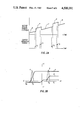
- FIGS. 7A-7C are graphical representations respectively of sensing electrode bias, background current and faradaic current which is to flow in the sensor shown in FIG. 4 during operation thereof.
- FIGS. 8A-8C are graphical representations respectively of sensing electrode bias, standard prior art sensor electrode background current and background current in the sensor shown in FIG. 4.
- FIG. 9 is a simplified, schematic, block diagram of an electronic system for detecting gas using real time, differential pulse detection in accordance with an exemplary embodiment of the present invention in its system aspect.
- FIG. 10 is constituted by a series of graphical representations of waveforms at various points in the electronic system shown in FIG. 9, these representations being helpful in understanding the operation thereof.
- Real time differential pulse detection according to the present invention is a modification of differential pulse voltammetry (DPV). Both specificity improvements and sensitivity gains on the order of 1,000 times have been realized in analytical instruments where conventional voltammetry has been replaced with DPV for reasons mentioned below.
- DPV differential pulse voltammetry
- Analytical instruments utilizing conventional voltammetry maintain an accurate potential between the sensing and reference electrodes of an electrochemical sensing cell.
- the potential is increased linearly over time, as illustrated by line V in FIG.. 1A.
- the current I which is proportional to the concentration of any species reacting at the potential on the sensing electrode, is then plotted vs. the potential of the sensing electrode, as illustrated in FIG.. 1B.
- Miniature detectors which are sometimes carried by individuals, utilizing conventional voltammetry cannot scan the electrode bias due to the extremely large capacitive background currents that would develop at the high surface area gas sensing electrodes when its bias is scanned. Instead, the sensing electrode bias is set at a fixed potential slightly above that where the gas to be detected undergoes a redox reaction.
- the sensing electrode of a detector designed to detect gas B would be set at E 2 .
- the current at this point, minus the background, is proportional to the concentration of gas B in the air.
- the major drawback of this prior art technique is that all gases oxidized below E 2 , that is at E 3 and E 4 for example, will act as interferents.
- gas A will act as an interferent to gas B in this example. If gas B is a typical gas to be detected, there are a significant number of gasses which act like A in most environments.
- FIG. 2A In prior art laboratory differential pulse voltammetry, as illustrated in FIG. 2A, a series of small pulses P are superimposed on a linearly increasing voltage ramp R. The current is measured just before the individual pulses and just before the end of the individual pulses as illustrated, respectively, as i o and i p .
- the DPV signal is the difference between the average current at the end of a pulse P and that before the pulse. Therefore, a current vs voltage plot for a DPV experiment yields a series of peaks instead of plateaus, as illustrated by the dashed lines in FIG. 2B. The peaks roughly coincide with the half wave potentials of conventional voltammetry.
- the specificity advantage of DPV becomes obvious when one examines FIG. 2B.
- the signal current at E 2 is proportional only to the background and gas B in the DPV mode. Gas A does not interfere since it is included in both the current before and at the end of the pulse.
- the signal current at E 3 has, in effect, been cancelled.
- the solid curves A and B, and the dashed curves A and B, in FIG. 2B represent respectively conventional and known DPV signals.
- the improvement in sensitivity is due to decreased concentration gradients at the electrode surface.
- the concentration gradient of the electroactive species at the electrode surface is the primary phenomenon limiting the sensitivity of most conventional voltammetry experiments.
- the concentration gradient is reduced in DPV, since the electroactive species is only depleted 20-300 milliseconds per second in a typical application.
- the present invention involves RDPD, which in some respects is similar to DPV.
- the major difference between the two are that (1) the pulses are superimposed on a fixed bias in RDPD instead of a linearly increasing voltage ramp, and (2) the RDPD signals are continuously sampled, held, and updated. Real time signal monitoring is accomplished since the update process occurs after each pulse.
- the fixed bias would be set at a small voltage, typically from about 5 mv to about 100 mv, below E 2 in FIG. 2B in a RDPD detector designed to detect gas B.
- a pulse of from about 10 msec. to about 200 msec., for example, a 20 msec. pulse of approximately 20 mv would be, superimposed periodically on the continuous fixed bias, in accordance with the present invention.
- the RDPD signal would be equal to the difference between the average current during the last 2 to 50 msec. of the pulse minus the average current during the last 2 to 50 mesc. before the pulse.
- Detectors based on RDPD display most of the sensitivity and specificity advantages of analytical DPV instruments.
- the background signal deviation associated with temperature fluctuations of detectors based on conventional voltammetry are eliminated, since both sampled currents i o and i p will vary equally with temperature.
- FIG. 3. which is known from the U.S. Pat. No. 3,776,832 to Oswin et al., supra, it is obvious that if one were to apply a potential of +1.0 V vs. the standard hydrogen electrode (SHE) to a voltametric cell in order to detect NO, C 2 H 5 0H and CO may also be oxidized and act as interferents. In practicing the present invention, however, one would apply a fixed bias between the sensing and reference electrodes, for example +0.90 V as shown in FIG. 5, slightly lower than potential of the redox couple to be detected.
- SHE standard hydrogen electrode
- a small additional pulse of approximately 0.20 V would be superimposed on the fixed potential such that the sum of the fixed potential and pulse would be greater than the half wave potential of the species to be detected (including overpotential).
- the current would be measured before each pulse and toward the end of each pulse as represented by i o and i p , in FIG. 5.
- the output signal would be the difference between the two measures or i p -i o .
- FIG. 4 A disposable module is illustrated in FIG. 4, the module including a pair of electrochemical detection cells constructed in accordance with the present invention.
- the two cells are operationally associated with a molded cell housing 10 made of a plastic, one of the cells 11 being shown fixed to the outside of the housing 10 by a plurality of screws 12.
- the other cell is shown for the purpose of illustration in an exploded configuration so as to show the relationship of its various components. It is to be understood that for most applications, a single cell would be provided and used. A pair of cells is provided for some applications.
- a pair of electrolyte-containing reservoirs are provided within the cell housing 10.
- the reservoirs communicate with respective apertures 14, 15 which extend through a top portion of the housing 10 and allow one to place an appropriate electrolyte in the respective reservoirs.
- the apertures 14, 15 are closed by appropriate plugs.
- the reservoir 13 is defined in part by a wall 16, which is partially visible through a broken away portion of the side wall of the housing 10.
- the wall 16 also constitutes the back wall of an ambient chamber 17 having its bottom defined by a portion of the housing 10.
- the chamber 17 is in fluid communication with the atmosphere or other gaseous ambient via at least one aperture 18 which extends through the bottom of the housing 10.
- the aperture 18 is shown somewhat larger relative to other features for the sake of clarity, it may be constituted by an aperture having a diameter of 0.02 inch.
- the exploded electrochemical detection cell includes a series of members held in stacked relationship over the chamber 17, when the cell is assembled for operation.
- the depth of chamber 17 is shown larger relative to other features for the sake of clarity. It may, in fact, be very shallow, for example, 0.1397 cm. (0.055 inch) in depth in a practical embodiment. It can be formed by a recess in a surface of the housing 10, the wall 16 being integral with the housing 10.
- the members include an apertured rectangular gasket 20 which is positioned about the open front of the chamber 17.
- the cell has, in the order named, in stacked relationship a polypropylene (PPE) membrane 21 which allows passage of O 2 while not allowing a large amount of interferent gases to pass, an electrode carrier 22 which may be realized as a porous polytetrafluoroethylene (PTFE) membrane or the like, two sheets of Whatman filter paper or another suitable hydrophilic insulator 23, 24, a membrane support 25, a further Whatman filter paper 26, an electrode carrier 27 which may be realized as a porous polytetrafluoroethylene (PTFE) or polypropylene membrane or the like, a permselective membrane 28 made, for example, of a molecular sieve or alumina impregnated with a reactive material such as potassium permanganate, an apertured rectangular gasket 29, a metal frame 30, and one or more grille members 31, 32.
- the membrane 28, when made as suggested above, is especially useful when one wishes to detect CO, while excluding passage of H 2 S, alcohols and several other gases.
- the electrode carrier 27 supports or is integral with a sensing electrode 33, the sensing electrode being preferably of a noble metal, for example, gold or of carbon, the noble metal or carbon being supported by and having been applied to a substrate of nickel or the like.
- the electrode 33 is desirably in the form of mesh or screen and could be a pure noble metal.
- the electrode carrier 22 supports a pair of spaced-apart electrodes 34, 35, these electrodes constituting respectively the reference electrode and counter electrode of the electrochemical detection cell of the present invention.
- the reference electrode 34 and counter electrode 35 like the sensing electrode 33, are preferably made of a noble metal, such as gold or platinum, or of carbon and have the form of a mesh or screen.
- the reference and counter electrodes could be composite electrodes fabricated from a finely divided conductive powder and an inert plastic binder, the conductive powder being, for example, metal or carbon powder.
- the reference electrode 34, the counter electrode 35 and the sensing electrode 33 because of their construction, present a large surface to the materials with which they come in contact, particularly the electrolyte and gas from the environment with which the sensing electrode 33 comes in contact with via the permselective membrane 28 and the grille members 31, 32.
- these electrodes are respectively provided with upwardly extending electrode portions 36, 37 and 38 and which may advantageously be extensions of the electrodes proper and be respective meshes.
- Each of the stacked members 20-22, 25, and 27-32 are provided the vicinity of their edges with a plurality of the aligned apertures 39, six being shown for purposes of illustration for each, through which respective screws 40 are to extend, the housing 10 including a corresponding and aligned plurality of threaded bores 41 which are to receive the screws 40 when the components are in assembled condition.
- the membrane support 25 is an insulating member and is provided on its upper-most edge with an insulating plate or extension 42 thereof which is fixed thereto or made integral therewith in a conventional fashion.
- Three, spaced-apart, electrical contacts 43, 44 and 45 extend upwardly from the insulating plate or extension 42 and through the insulating plate or extension 42 so as to provide respective contact areas beneath the insulating plate or extension 42 which contact respectively with the upwardly extending respective metal portions 38, 36 and 37 of the respective counter electrode 35, the sensing electrode 33 and the reference electrode 34, when the exploded cell is in its assembled condition.
- the contacts 43-45 are preferably made by the same conductive material as the portions 38, 36 and 37 of the electrodes and, if desired, may be fixed thereto by a conductive epoxy resin containing the same metals.
- An aperture 46 extends through the housing 10 into the reservoir 13 and has therein a wick 47 which, when the members are assembled, extends through a passageway defined by respective aligned apertures 48 in the gasket 20, the membrane 21, the electrode support 22 and the membrane support 25 so as to supply electrolyte from the reservoir 13 to the Whatman filter papers 23, 24 and 26 between the sensing electrode 33 and the reference and counter electrodes 34, 35.
- a further aperture 50 extends through the housing 10 and into the reservoir 13, the aperture 50 defining a passageway, when aligned with apertures 51 in the membrane 21 and the gasket 20, between the space between the electrodes 33, 34, 35 via a slot 53 in the top portion of the membrane support 25 to allow gas produced to move to reservoir 13 thereinto.
- the disposable module includes between the two electrochemical sensing cells a portion shown as an elongated, longitudinal protrusion 52 which includes within it a battery for powering the electronic system of the present invention.
- the battery within the portion of the module behind the protrusion 52 is conductively connected to the electronic system of the present invention via electrical contacts 54, 55.
- the electronic portion of the invention as illustrated in some detail in FIG. 9, is physically located on the top portion of the cell housing 10 and is electrically connected to the electrical contacts 43-45, 54 and 55.
- the contacts 54, 55 also are connected to supply power to a second electronic system located on the top portion of the housing 10 and which corresponds to that of FIG. 9, but is set to detect a different gas or is present as a redundant system to assure a high degree of reliability, this second electronic system being associated with the cell 11 via three contacts (unnumbered) which correspond to the contacts 43-45.
- the electronic system including a small buzzer or other audible alarm, is carried within the casing generally designated by the numeral 56.
- the casing 56 includes a pair of side walls 57, 58, a backwall 59 and a front wall 60.
- the front wall 60 does not extend longitudinally to the same extent as the side walls 57, 58 and the back wall 59 so as to provide an opening 61 having a vertical extent such that when the disposable module housing 10 is inserted into the casing 56, the outermore grille member 32 of the one cell and the corresponding grille member of the other cell 11, as well as the protruding portion 52 of the cell housing 10 which contains the battery for the electronic system, will not be covered.
- the casing 60 is open at the bottom so that the cell housing 10 can be easily inserted into it from the bottom with its respective electrical contacts 43-45 and corresponding ones associated with the cell 11 and contacts 54, 55 coming into contact with appropriate connectors associated with the two respective electronic systems which are carried within the casing 60.
- the top wall 62 of the casing 56 includes a grill work 63, behind which an appropriate buzzer or audible alarm (not visible) for sounding an alarm signal is provided.
- An alligator clip 64 is fixedly connected with an upstanding tab 65 of the casing 56 so as to provide a means connecting the alarm unit, constitued by the casing 56 and the disposable cell module within it, to the shirt pocket or the like of a user.
- the cell housing 10 is removably held within the casing 56 by a pair of detents, only one detent 66 being visible on one of the side surfaces of the cell housing 10, a corresponding detent being and on its corresponding outwardly facing side surface, which is not visible.
- the detents 66 cooperate with a pair of detents which are present on opposed, inwardly facing side surfaces of the casing 56, only one groove 67 being visible.
- the real time differential pulse detection (RDPD) sensor shown in FIG. 4 allows one to use the differential pulse technique to improve both the specificity and sensitivity of electrochemical cells adapted to detect various species in a gaseous environment.
- the construction of the sensor is similar to those described in the U.S. Letters Patents of Oswin et al., supra, and Stetter, supra, with the exception of the arrangement of parts and electrode differences; the metal electrodes 33-35 are configured in such a way to provide low resistance and a very low dual layer capacitance, are spaced close together.
- the sensing electrode 33 is sandwiched between a gas permeable membrane 28 and a hydrophilic insulator, in the form of Whatman filter papers 23, 24 and 26, soaked with the electrolyte, so the sensor can be operated in any orientation or during movement.
- the filter papers 23, 24 and 26 are positioned between the sensing electrode 33 and each of the reference electrode 34 and the counter electrode 35 allowing effective application of the electrolyte while maintaining close spacing.
- the polypropylene membrane 21 serves the purpose of protecting the reference electrode 34 from interferents.
- the metals preferably used to construct the sensing electrode 33 can be operated at much higher potentials than mercury, allowing one to detect both oxidizable and reducible gases, unlike the sensor disclosed in the Letters Patent to David et al., supra.
- these materials should be selected and used in such concentration taking into account expected operating conditions and safety factors, so as to assure that the materials will not precipitate out of solution while using a solution which is as concentrated as practicable.
- aqueous solutions of H 2 SO 4 , KOH and KCl are examples of many materials which can be used for the electrolyte.
- FIGS. 7A-7C depict characteristics of the RDPD sensor of the present invention in which cyanide is oxidized on a silver or gold sensing electrode.
- the sensing electrode potential with respect to the reference electrode is periodically pulsed from zero mV to 50 mV, as shown in FIG. 7A.
- Charging the sensing electrode to its new potential results in a positive spike at the beginning of each pulse and a negative spike at the end of each pulse, as shown in FIG. 7B.
- the capacitive background current occurs in both the absence or presence of the gas to be detected. If the gas to be detected is present, the Faradaic signal current shown in FIG. 7C is superimposed on the background capacitive current of FIG. 7B.
- n number of electrons transferred per molecule of gas
- the DPV signal is the difference current, that is i p -i o . Therefore most interferents are removed when the electronics system subtracts i p -i o .
- Equation (2) states that the signal level is inversely proportional to the square root of the time after the pulse begins. Since the signal is measured at the end of the pulse, maximum sensitivity is achieved by minimizing the pulse width. The minimum size of the pulse width is determined by the time required for the capacitive background current to decay, since it masks the Faradaic gas signal until it decays to nearly zero.
- electrodes used in prior art gas sensors exhibit a very slow background current decay, which severaly limits their sensitivity. Their extraordinary large electrode surface area cause a slow background current decay due to the large R and C terms in equation (1), supra.
- the background current problem of prior art electrodes used in the RDPD mode is overcome in this invention by using noble metal screen electrodes or the like and placing them in relation to the other parts as described above. This decreases the R and C terms described in equation (1), supra, of the sensor several orders of magnitude, and results in the improvement in the background signal shown in FIG. 8C as compared to the standard background current shown in FIG. 8B.
- the background signal improvement allows one to utilize shorter pulses, which increases the sensitivity as described in equation (2).
- the shorter pulse allows measurement of the gas signal before it has decayed to the degree in the U.S. Letters Patent to David et al., supra.
- the short pulse typically about 50 msec. long, is only repeated once every second (50 msec. on-950 msec. off), in contrast to the 200 msec. on-200 msec. off cycle used in the prior art. It has been established in the literature that the sensitivity decreases as the pulse on-off ratio increases.
- FIG. 9 a suitable, exemplary electronic system for real time, differential pulse detection, which is particularly useful when operably associated with the detection cell shown in FIG. 4 is illustrated.
- the real time, differential pulse detection electronic system includes a control circuit 68 having three syncronizing outputs, a function generator 69 responsive to one output from the control circuit 68 and having one output, a detection cell 70, which corresponds to the cell shown in exploded configuration and FIG. 4, and a transducing network (potentiostat) 71 which generates voltage and/or current signals proportional to the amount of agent reacting at the sensing electrode 33.
- a control circuit 68 having three syncronizing outputs
- a function generator 69 responsive to one output from the control circuit 68 and having one output
- a detection cell 70 which corresponds to the cell shown in exploded configuration and FIG. 4
- a transducing network (potentiostat) 71 which generates voltage and/or current signals proportional to the amount of agent reacting at the sensing electrode 33.
- the output from the transducing network 71 is coupled to an analog processing circuit 72, which is controlled by two of the output from the control circuit 68, and has its output coupled to a buffered, sample-and-hold circuit 73.
- the output from the sample-and-hold circuit 73 is fed to a threshold circuit 74 which, in turn, has its output fed to an audible alarm circuit 75 which may be constituted by a buzzer, and to a visible alarm circuit 116, which may be constituted by a light-emitting-diode (L.E.D.).
- control circuit 68, the function generator 69, the transducing network 71 and the analog processing circuit 72 may be realized as a miniaturized circuit which can be positioned adjacent to a top portion of the cell housing 10 (FIG. 4) and in electrical connection with contacts 43-45 and 54,55 (FIG. 4), while the buffered, sample-and-hold circuit 73, the alarm circuits 75 and 116, and the threshold circuit 74 are desirably carried separately within the casing 56 (FIG. 6). It is to be appreciated that the output of a second analog processing circuit, associated with the second detecting cell 11 (FIG.
- the buffered, sample-and-hold circuit 73 could be realized as part of a single disposable unit with the control circuit 68, the function generator 69, the transducing network 71 and the analog processing circuit 72 were a single real time differential pulse detection system, rather than two such systems, utilized.
- the power for the circuit illustrated in FIG. 9 is obtained from a battery pack (not illustrated) which includes a ground midpoint, a V+ voltage terminal and a V- voltage terminal.
- a 4K ohm resistor 76, a first voltage reference 77, a second voltage reference 78 and a 4K ohm resistor 79 are connected in series with one another in the order named between the V+ and the V- terminals, the reference point (ground) being provided between the anode and cathode of the respective voltage references 77 and 78.
- the voltage references 77 and 78 provide for a constant steady D.C. voltage across the same.
- a first voltage divider constituted by the series connection of a 1K ohm resistor 80, a 10K ohm potentiometer 81 and a 1K ohm resistor 82 connected in series, is connected across the voltage references 77, 78.
- a second voltage divider constituted by the series connection of a 1K ohm resistor 83, a 10K ohm potentiometer 84 and a 1K ohm resistor 85 is connected in parallel with the voltage references 77, 78.
- the wiper of the potentiometer 81 is connected to the non-inverting (+) terminal of an operational amplifier 86, arranged in a non-inverting amplifier, which has its inverting (-) terminal connected to ground via a 10K ohm resistor 87 and its output terminal connected to its inverting terminal via a 20K ohm resistor 88.
- the operational amplifier 86 with its associated circuit components, is configured to buffer and to amplify the voltage supplied from the potentiometer 81.
- the wiper of the potentiometer 84 is connected to the non-inverting (+) terminal of an operational amplifier 89 which is connected as a unity gain buffer and has its output terminal directly connected to its inverting terminal.
- the output terminals of the operational amplifiers 86 and 89 are coupled to the inverting (-) terminal of a further operational amplifier 90 arranged as a summing, inverting amplifier, the output terminal of the operational amplifier 86 being connected via a 10K ohm resistor 91, while the output terminal of the operational amplifier 89 is connected via a series connection of a controlled analog switch 92 and a 10K ohm resistor 93.
- the non-inverting (+) terminal of the operational amplifier 90 is connected to ground via a 5K ohm resistor 94 and its output terminal is connected to its inverting input terminal via a 10K ohm resistor 95.
- a synchronized output from the control circuit 68 having the form of the waveform illustrated as waveform C in FIG. 10, is coupled to the enabling input of the analog switch 92.
- the final stage, operational amplifier 90, of the function generator 69 has its output terminal connected directly to the non-inverting (+) input terminal of an operational amplifier 96, the first stage of the transducing network (potentiostat) 71.
- the output terminal of the operational amplifier 96 is connected to the counter electrode 35 of the detection cell 70.
- the inverting (-) input terminal of the operational amplifier 96 is connected to the reference electrode 34 of the detection cell 70.
- the output and inverting input terminals of the operational amplifier 96 being coupled together via a 0.1 ⁇ f capacitor 97, so as to reduce the possiblity of the operational amplifier 96, and its associated circuitry undesirably going into oscillation.
- the detection cell 70 includes a sensing electrode 33, which is also shown in FIG. 4, is coupled to the inverting (-) terminal of an operational amplifier 98, via a 33 ohm resistor 99 which provides noise reduction.
- the non-inverting (+) terminal of the operational amplifier 98 is connected to ground, the output terminal thereof being connected to its inverting (-) input terminal via a 2.2K ohm resistor 100.
- the resistor 100 can be considered, in association with the other circuit components connected to the operational amplifier 98, to effect a current-to-voltage conversion, the resistor 100 determining the conversion gain.
- the output terminal of the operational amplifier 98 is connectd via a 5K ohm resistor 101, to the respective input terminals of controlled analog switches 102 and 103, which are the input stages of the analog processing circuit 72.
- the respective controlling inputs to the analog switches 102 and 103 are obtained from the control circuit 68 via connections thereto, the respective controlling inputs being constituted by signals corresponding to the waveforms shown in FIG. 10 as letter A and letter B, respectively.
- the respective output terminals from the analog switches 102, 103 are respectively connected to the ungrounded side of 0.1 ⁇ f capacitors 104 and 105.
- the opposite plates of the capacitors 104 and 105 being connected to ground.
- the ungrounded sides of the respective capacitors 104, 105 are connected respectively to the non-inverting (+) input terminals of respective operational amplifiers 106 and 107, the respective output terminals and inverting (-) input terminals of the respective amplifiers 106 and 107 being connected via respective 22K ohm resistors 108 and 109.
- the output terminal of the operational amplifier 106 is connected to the inverting (-) input terminal of the operational amplifier 107 via a 22K ohm resistor 110.
- the inverting (-) input terminal of the operational amplifier 106 is connected to ground via a 22K ohm resistor 111.
- the output terminal of the operational amplifier 107 which constitutes the output from the analog processing circuit 72, is connected to a controlled analog switch 112 which forms the input stage of the buffered, sample-and-hold circuit 73.
- the enabling input to the controlled analog switch 112 is obtained from the control circuit 68 via the connection thereto which also provides the same enabling input signal to the controlled analog switch 103, this signal being shown as a waveform B in FIG. 10.
- the output from the analog switch 112 is fed to the unground plate of a 0.1 ⁇ f capacitor 113, its other plate being grounded.
- the capacitor 113 has its ungrounded plate connected to the non-inverting (+) input terminal of an operational amplifier 114, the inverting (-) input terminal of the operational amplifier 114 being directly connected to the output terminal thereof, which constitutes the output from the buffered, sample-and-hold circuit 73.
- the output terminal from the operational amplifier 114 is connected to a first input terminal of a threshold comparator 115 which has its other input terminal connected to a wiper of a potentiometer 116 which, as shown, is connected between the V+ and V- terminals of the battery pack power source.
- the potentiometer 116 could be connected in parallel with the voltage references 77, 78 for better regulation.
- the output from the threshold comparator 115 which constitutes the output of the threshold circuit 74, is connected to the audible alarm circuit 75, illustrated as a buzzer.
- the output of the threshold comparator 115 is also fed to a visible alarm circuit 117, illustrated as a light emitting diode (L.E.D.) 116 which may be powered from a switched power source or in some cases, an oscillator which would cause the L.E.D. 116 to blink on and off.
- the operational amplifiers 86, 89, 90, 96, 98, 106, 107 and 114 can be realized from respective one-quarters of two quad CMOS OP AMPS e.g. Intersil's ICL 7641 circuit modules.
- the user first determines which gas is to be detected, and selects the appropriate electrolyte which is placed in the electrolyte reservoir 13 (FIG. 4). This electrolyte, because of the wick 47 which extends from the reservoir 13 and to physical contact with the Whatman filter papers 23, 24 and 26 (FIG. 4), transfers some electrolyte into space between the sensing electrode 33 and each of the counter electrode 35 and the reference electrode 34.
- the output terminal of the operational amplifier 96 and its inverting input terminal are directly respectively connected conductively to the counter electrode 35 and the reference electrode 34 of the detection cell 70, as pointed out above.
- control circuit 68 which may be realized as a timing circuit which includes a master oscillator, counters and logic circuits, so as to produce the appropriate control pulses, shown as waveform A-C in FIG. 10, in timed, synchronized sequence.
- the control circuit 68 when turned on by user as suggested by the START input produces a train of short, for example ten msec. pulses, the pulses being shown as waveform A in FIG. 10, the individual pulses acting to enable the analog switch 102 which, when enabled, effects a transfer of the output signal from the operational amplifier 98 of the transducing network 71 to charge the storage capacitor 104 during the duration of the enabling pulse.
- This results in a voltage across the capacitor 104 which corresponds to the current produced from the transducing network 71 which responds to output from the sensing electrode 33 (FIGS. 4, 9) the detection cell just prior to the superposition of the differential D.C. pulse on the aforementioned and already present fixed-background-bias D.C.
- the pulse control circuit 68 produces, at the trailing edge of each of these pulses, respective control pulses of, for example, 40 msec. lengths having the waveform C illustrated in FIG. 10 which enables the analog gate 92, causing a representation of the D.C. voltage output from the operational amplifier 89 to be superimposed on the fixed-background-bias D.C. potential output from the operational amplifier 86 as set by the placement of the wiper of the potentiometer 81.
- the reference electrode 34 exhibits an increase in voltage thereof for the duration of the individual control pulses illustrated as waveform C in FIG. 10.
- the control circuit 68 produces a further 10 msec. enabling pulse which is applied to the respective analog switches 103 and 112 so as to enable these respective analog switches and in effect, transfer the difference between the stored signals appearing across the capacitors 104 and 105 to the buffered sample-and-hold circuit 73 via the operational amplifier 107 and, in particular, to the capacitor 113.
- the capacitors 104 and 105 are identical in size, therefore the respective voltages which appear on these respective capacitors correspond respectively to currents produced from the transducing network 71 which respectively correspond to the voltages produced from the detection cell 70 just before the beginning and just before the end of each of the pulses shown in FIG. 10 as waveform C and which are used to enable the analog switch 92.
- the signals from the operational amplifier 107 are thus periodically stored on the capacitor 113 and the production thereof, at least over a given special level, indicates the presence of an agent to be detected, such as a gas, and which has been detected by the detection cell 70.
- the buffered, sample-and-hold circuit 73 holds the highest level it receives from the operational amplifier 107, which output is fed to the operational amplifier 114 which has its output coupled to the threshold circuit 74, in particular, to one input of the threshold comparator 115, which has its other input connected to the adjustable threshold level setting potentiometer 116.
- the threshold comparator 115 Whenever the output from the operational amplifier 114 exceeds the voltage supplied from the potentiometer 116, the threshold comparator 115 provides an output which enables the alarm circuits 75 and 116 or one of them if only one is present, these alarm circuits being shown as a buzzer and an L.E.D. In instances where the L.E.D. alarm circuit 116 is provided, it is turned on by an output from the threshold comparator 115, blinking in the case an oscillator is used to supply the power to the L.E.D. via a controlled switch (not shown) responsive to output from the threshold comparator 115.
- the output from the amplifier 114 could be used alternatively or in addition to effecting the turning on of the alarm circuits 75 and 116, to provide a direct analog readout to a meter or the like or be associated with digital storage and/or display and/or further processing.
Abstract
Description
______________________________________
U.S. Letters Pat.
            Nelms et al.  August 9, 1977
No. 4,040,805
U.S. Letters Pat.
            David et al.  September 13, 1977
No. 4,048,041
U.S. Letters Pat.
            Dempsey et al.
                          October 14, 1980
No. 4,227,984
U.S. Letters Pat.
            Kring et al.  November 25, 1980
No. 4,235,097
U.S. Letters Pat.
            Diller et al. June 2, 1981.
No. 4,271,121
______________________________________
______________________________________
U.S. Letters Pat. No. 3,420,764
                 Schlein     January 7, 1969
U.S. Letters Pat. No. 4,253,847
                 Matson et al.
                             March 3, 1981
U.S. Letters Pat. No. 4,321,322
                 Ahnell      March 23, 1982.
______________________________________
Claims (24)
Priority Applications (5)
| Application Number | Priority Date | Filing Date | Title |
|---|---|---|---|
| US06/541,631 US4500391A (en) | 1983-10-13 | 1983-10-13 | Method of and system for real time differential pulse detection |
| CA000464507A CA1219910A (en) | 1983-10-13 | 1984-10-02 | Method of and system for real time differential pulse detection (rdpd) |
| EP84111859A EP0141282B1 (en) | 1983-10-13 | 1984-10-04 | Method of and system for real time differential pulse detection |
| DE8484111859T DE3478057D1 (en) | 1983-10-13 | 1984-10-04 | Method of and system for real time differential pulse detection |
| JP59212757A JPS60149960A (en) | 1983-10-13 | 1984-10-12 | Method and system of detecting gas |
Applications Claiming Priority (1)
| Application Number | Priority Date | Filing Date | Title |
|---|---|---|---|
| US06/541,631 US4500391A (en) | 1983-10-13 | 1983-10-13 | Method of and system for real time differential pulse detection |
Publications (1)
| Publication Number | Publication Date |
|---|---|
| US4500391A true US4500391A (en) | 1985-02-19 |
Family
ID=24160396
Family Applications (1)
| Application Number | Title | Priority Date | Filing Date |
|---|---|---|---|
| US06/541,631 Expired - Fee Related US4500391A (en) | 1983-10-13 | 1983-10-13 | Method of and system for real time differential pulse detection |
Country Status (5)
| Country | Link |
|---|---|
| US (1) | US4500391A (en) |
| EP (1) | EP0141282B1 (en) |
| JP (1) | JPS60149960A (en) |
| CA (1) | CA1219910A (en) |
| DE (1) | DE3478057D1 (en) |
Cited By (20)
| Publication number | Priority date | Publication date | Assignee | Title |
|---|---|---|---|---|
| US4631116A (en) * | 1985-06-05 | 1986-12-23 | Hughes Aircraft Company | Method of monitoring trace constituents in plating baths |
| EP0226768A2 (en) * | 1985-12-23 | 1987-07-01 | Environmental Technologies Group, Inc. | Method and apparatus for operating electrochemical detector cell |
| EP0269794A2 (en) * | 1986-11-07 | 1988-06-08 | Environmental Technologies Group, Inc. | Method for operating an electrochemical cell having redox potential applied thereto |
| US4917775A (en) * | 1984-10-30 | 1990-04-17 | Outokumpu Oy | Method for measuring and adjusting electrochemical potential and/or component content in the process of treating valuable materials |
| US5117680A (en) * | 1990-12-26 | 1992-06-02 | Ford Motor Company | Method and control circuit for measuring trace constituents in automotive engine exhaust |
| US5126034A (en) * | 1988-07-21 | 1992-06-30 | Medisense, Inc. | Bioelectrochemical electrodes |
| US5262034A (en) * | 1992-10-23 | 1993-11-16 | International Fuel Cells Corporation | Electrochemical sensor for monitoring electrochemical potentials of fuel cell components |
| EP0569826A1 (en) * | 1992-05-12 | 1993-11-18 | Hughes Aircraft Company | Method and system for monitoring quality of phosphate coating |
| FR2700393A1 (en) * | 1993-01-14 | 1994-07-13 | Souchon Neuvesel Verreries | Determination of the state of oxidation of a molten material |
| US5554269A (en) * | 1995-04-11 | 1996-09-10 | Gas Research Institute | Nox sensor using electrochemical reactions and differential pulse voltammetry (DPV) |
| US5611909A (en) * | 1994-12-22 | 1997-03-18 | Dragerwerk Aktiengesellschaft | Method for detecting source of error in an amperometric measuring cell |
| US5611908A (en) * | 1994-12-22 | 1997-03-18 | Dr agerwerk Aktiengesellschaft | Method of operating and amperometric measuring cell |
| FR2785679A1 (en) * | 1998-11-06 | 2000-05-12 | Draeger Sicherheitstech Gmbh | OPERATING METHOD FOR AN ELECTROCHEMICAL MEASUREMENT CELL |
| US6416651B1 (en) * | 1999-02-26 | 2002-07-09 | Honeywell Measurex | Multi-electrode composition measuring device and method |
| US20050284772A1 (en) * | 2004-06-18 | 2005-12-29 | Bjr Sensors, Llc. | Method of sensor conditioning for improving signal output stability for mixed gas measurements |
| US20060063284A1 (en) * | 2004-09-22 | 2006-03-23 | Asm Japan K.K. | DC bias voltage measurement circuit and plasma CVD apparatus comprising the same |
| DE19882506B4 (en) * | 1997-07-02 | 2009-01-02 | Mine Safety Appliances Co. | Electrochemical sensor for detecting hydrogen cyanide and method for using the electrochemical sensor |
| US20090078587A1 (en) * | 2004-06-18 | 2009-03-26 | Bjr Sensors, Llc | Method of Sensor Conditioning for Improving Signal Output Stability for Mixed Gas Measurements |
| US10197525B2 (en) * | 2015-12-21 | 2019-02-05 | Msa Technology, Llc | Pulsed potential gas sensors |
| CN112166318A (en) * | 2018-03-30 | 2021-01-01 | 株式会社普欧威盖特 | Electric circuit for electrochemical measurement and measuring device |
Families Citing this family (5)
| Publication number | Priority date | Publication date | Assignee | Title |
|---|---|---|---|---|
| JPH0736009B2 (en) * | 1984-02-24 | 1995-04-19 | テルモ株式会社 | Ion concentration measuring device |
| JPH0762667B2 (en) * | 1987-12-11 | 1995-07-05 | 株式会社日立製作所 | Solution quantitative analysis device, quantitative analysis method, and water quality control system for nuclear reactor |
| US5186798A (en) * | 1987-12-11 | 1993-02-16 | Hitachi, Ltd. | Solution quantitative analysis apparatus, quantitative analysis methods, and nuclear reactor water quality control system |
| DE4030873C2 (en) * | 1990-09-29 | 2000-05-04 | Conducta Endress & Hauser | Method for determining the concentration of electrochemically convertible gases |
| JP4759734B2 (en) * | 2005-09-29 | 2011-08-31 | 国立大学法人 千葉大学 | Hydroponics equipment |
Citations (2)
| Publication number | Priority date | Publication date | Assignee | Title |
|---|---|---|---|---|
| US4340885A (en) * | 1979-09-24 | 1982-07-20 | Super Shops, Inc. | Gas detector |
| US4388822A (en) * | 1981-07-15 | 1983-06-21 | Mine Safety Appliances Company | Atmospheric sampling system |
Family Cites Families (7)
| Publication number | Priority date | Publication date | Assignee | Title |
|---|---|---|---|---|
| US3420764A (en) * | 1964-03-16 | 1969-01-07 | North American Rockwell | Electrochemical analysis system |
| US3776832A (en) * | 1970-11-10 | 1973-12-04 | Energetics Science | Electrochemical detection cell |
| US3755125A (en) * | 1971-01-14 | 1973-08-28 | Envirometrics Inc | Electrochemical gas analyzer |
| US3925183A (en) * | 1972-06-16 | 1975-12-09 | Energetics Science | Gas detecting and quantitative measuring device |
| US4017373A (en) * | 1976-04-05 | 1977-04-12 | Interscan Corporation | Electrochemical sensing cell |
| US4048041A (en) * | 1976-05-24 | 1977-09-13 | The United States Of America As Represented By The Secretary Of The Army | Electronic system for providing specificity in an electrochemical analytical device |
| US4227984A (en) * | 1979-03-01 | 1980-10-14 | General Electric Company | Potentiostated, three-electrode, solid polymer electrolyte (SPE) gas sensor having highly invariant background current characteristics with temperature during zero-air operation |
-
1983
- 1983-10-13 US US06/541,631 patent/US4500391A/en not_active Expired - Fee Related
-
1984
- 1984-10-02 CA CA000464507A patent/CA1219910A/en not_active Expired
- 1984-10-04 EP EP84111859A patent/EP0141282B1/en not_active Expired
- 1984-10-04 DE DE8484111859T patent/DE3478057D1/en not_active Expired
- 1984-10-12 JP JP59212757A patent/JPS60149960A/en active Pending
Patent Citations (2)
| Publication number | Priority date | Publication date | Assignee | Title |
|---|---|---|---|---|
| US4340885A (en) * | 1979-09-24 | 1982-07-20 | Super Shops, Inc. | Gas detector |
| US4388822A (en) * | 1981-07-15 | 1983-06-21 | Mine Safety Appliances Company | Atmospheric sampling system |
Non-Patent Citations (2)
| Title |
|---|
| D. G. Swartzfager, Anal. Chem., vol. 48, No. 14, pp. 2189 2192, Dec. 1976. * |
| D. G. Swartzfager, Anal. Chem., vol. 48, No. 14, pp. 2189-2192, Dec. 1976. |
Cited By (29)
| Publication number | Priority date | Publication date | Assignee | Title |
|---|---|---|---|---|
| US4917775A (en) * | 1984-10-30 | 1990-04-17 | Outokumpu Oy | Method for measuring and adjusting electrochemical potential and/or component content in the process of treating valuable materials |
| US4631116A (en) * | 1985-06-05 | 1986-12-23 | Hughes Aircraft Company | Method of monitoring trace constituents in plating baths |
| EP0226768A3 (en) * | 1985-12-23 | 1989-10-11 | Allied Corporation | Method and apparatus for operating electrochemical detector cell |
| EP0226768A2 (en) * | 1985-12-23 | 1987-07-01 | Environmental Technologies Group, Inc. | Method and apparatus for operating electrochemical detector cell |
| US4735691A (en) * | 1985-12-23 | 1988-04-05 | Allied Corporation | Method for operating electrochemical detector cell |
| EP0269794A2 (en) * | 1986-11-07 | 1988-06-08 | Environmental Technologies Group, Inc. | Method for operating an electrochemical cell having redox potential applied thereto |
| EP0269794A3 (en) * | 1986-11-07 | 1989-08-30 | Environmental Technologies Group, Inc. | Method for operating an electrochemical cell having redox potential applied thereto |
| US5126034A (en) * | 1988-07-21 | 1992-06-30 | Medisense, Inc. | Bioelectrochemical electrodes |
| US5117680A (en) * | 1990-12-26 | 1992-06-02 | Ford Motor Company | Method and control circuit for measuring trace constituents in automotive engine exhaust |
| EP0569826A1 (en) * | 1992-05-12 | 1993-11-18 | Hughes Aircraft Company | Method and system for monitoring quality of phosphate coating |
| US5324399A (en) * | 1992-05-12 | 1994-06-28 | Hughes Aircraft Company | Method and system for monitoring quality of phosphate coating |
| US5262034A (en) * | 1992-10-23 | 1993-11-16 | International Fuel Cells Corporation | Electrochemical sensor for monitoring electrochemical potentials of fuel cell components |
| FR2700393A1 (en) * | 1993-01-14 | 1994-07-13 | Souchon Neuvesel Verreries | Determination of the state of oxidation of a molten material |
| US5611909A (en) * | 1994-12-22 | 1997-03-18 | Dragerwerk Aktiengesellschaft | Method for detecting source of error in an amperometric measuring cell |
| US5611908A (en) * | 1994-12-22 | 1997-03-18 | Dr agerwerk Aktiengesellschaft | Method of operating and amperometric measuring cell |
| US5554269A (en) * | 1995-04-11 | 1996-09-10 | Gas Research Institute | Nox sensor using electrochemical reactions and differential pulse voltammetry (DPV) |
| DE19882506B4 (en) * | 1997-07-02 | 2009-01-02 | Mine Safety Appliances Co. | Electrochemical sensor for detecting hydrogen cyanide and method for using the electrochemical sensor |
| FR2785679A1 (en) * | 1998-11-06 | 2000-05-12 | Draeger Sicherheitstech Gmbh | OPERATING METHOD FOR AN ELECTROCHEMICAL MEASUREMENT CELL |
| US6416651B1 (en) * | 1999-02-26 | 2002-07-09 | Honeywell Measurex | Multi-electrode composition measuring device and method |
| US7585402B2 (en) * | 2004-06-18 | 2009-09-08 | Bjr Sensors, Llc | Method of sensor conditioning for improving signal output stability for mixed gas measurements |
| US20090078587A1 (en) * | 2004-06-18 | 2009-03-26 | Bjr Sensors, Llc | Method of Sensor Conditioning for Improving Signal Output Stability for Mixed Gas Measurements |
| US20050284772A1 (en) * | 2004-06-18 | 2005-12-29 | Bjr Sensors, Llc. | Method of sensor conditioning for improving signal output stability for mixed gas measurements |
| US20060063284A1 (en) * | 2004-09-22 | 2006-03-23 | Asm Japan K.K. | DC bias voltage measurement circuit and plasma CVD apparatus comprising the same |
| WO2006138094A3 (en) * | 2005-06-15 | 2008-12-31 | Boris Farber | Method of sensor conditioning for mixed gas measurements |
| US10197525B2 (en) * | 2015-12-21 | 2019-02-05 | Msa Technology, Llc | Pulsed potential gas sensors |
| AU2016375264B2 (en) * | 2015-12-21 | 2020-07-30 | Msa Technology, Llc | Pulsed potential gas sensors |
| CN112166318A (en) * | 2018-03-30 | 2021-01-01 | 株式会社普欧威盖特 | Electric circuit for electrochemical measurement and measuring device |
| EP3779426A4 (en) * | 2018-03-30 | 2021-12-15 | Provigate Inc. | Electrical circuit for electrochemical measurement and measurement device |
| CN112166318B (en) * | 2018-03-30 | 2023-06-23 | 株式会社普欧威盖特 | Electrical circuit for electrochemical measurement and measurement device |
Also Published As
| Publication number | Publication date |
|---|---|
| EP0141282A1 (en) | 1985-05-15 |
| CA1219910A (en) | 1987-03-31 |
| EP0141282B1 (en) | 1989-05-03 |
| DE3478057D1 (en) | 1989-06-08 |
| JPS60149960A (en) | 1985-08-07 |
Similar Documents
| Publication | Publication Date | Title |
|---|---|---|
| US4500391A (en) | Method of and system for real time differential pulse detection | |
| US5217595A (en) | Electrochemical gas sensor | |
| US3454485A (en) | Oxygen sensor with scavenger means | |
| US3260656A (en) | Method and apparatus for electrolytically determining a species in a fluid | |
| US4025412A (en) | Electrically biased two electrode, electrochemical gas sensor with a H.sub.2 | |
| US4406770A (en) | Gas sensor | |
| US3325378A (en) | Electrochemical method and apparatus for measuring hydrogen content | |
| US4525266A (en) | Electrochemical gas sensor | |
| JPH057657B2 (en) | ||
| US4735691A (en) | Method for operating electrochemical detector cell | |
| US3223597A (en) | Method and means for oxygen analysis of gases | |
| JPS634660B2 (en) | ||
| CA2360595C (en) | Hybrid film type sensor | |
| GB2164156A (en) | Electrochemical gas sensor | |
| GB2097931A (en) | Carbon dioxide measurement | |
| US3855096A (en) | Electrochemical cells | |
| US4057478A (en) | Electrochemical gas monitor | |
| US4166775A (en) | Electrochemical gas monitoring method | |
| US4591414A (en) | Method of determining methane and electrochemical sensor therefor | |
| US4152233A (en) | Apparatus for electrochemical gas detection and measurement | |
| US3258415A (en) | Oxygen analyzer and oxygen-depolarized cell therefor | |
| US3824166A (en) | Trace gas analyzer | |
| US4595486A (en) | Electrochemical gas sensor | |
| US5334295A (en) | Micro fuel-cell oxygen gas sensor | |
| JPH02297054A (en) | Electrochemical measuring cell for measuring ammonia or hydrazine in gaseous or liquid measuring sample |
Legal Events
| Date | Code | Title | Description |
|---|---|---|---|
| AS | Assignment |
Owner name: ALLIED CORPORATION, COLUMBUS ROAD, ANDPARK AVENUE, Free format text: ASSIGNMENT OF ASSIGNORS INTEREST.;ASSIGNORS:SCHMIDT, JOHN C.;SANDS, CLIFTON A.;CAMPBELL, DONALD N.;REEL/FRAME:004257/0889;SIGNING DATES FROM 19840508 TO 19840509 Owner name: ALLIED CORPORATION, A CORP OF NY, NEW JERSEY Free format text: ASSIGNMENT OF ASSIGNORS INTEREST;ASSIGNORS:SCHMIDT, JOHN C.;SANDS, CLIFTON A.;CAMPBELL, DONALD N.;SIGNING DATES FROM 19840508 TO 19840509;REEL/FRAME:004257/0889 |
|
| AS | Assignment |
Owner name: ALLIED CORPORATION, COLUMBIA ROAD & PARK AVENUE, M Free format text: ASSIGNMENT OF ASSIGNORS INTEREST.;ASSIGNOR:BENDIX CORPORATION, THE, A DE CORP;REEL/FRAME:004301/0126 Effective date: 19840828 |
|
| FEPP | Fee payment procedure |
Free format text: PAYOR NUMBER ASSIGNED (ORIGINAL EVENT CODE: ASPN); ENTITY STATUS OF PATENT OWNER: SMALL ENTITY |
|
| FPAY | Fee payment |
Year of fee payment: 4 |
|
| AS | Assignment |
Owner name: ENVIRONMENTAL ANALYTICAL SYSTEMS, INC., A DE CORP. Free format text: ASSIGNMENT OF ASSIGNORS INTEREST.;ASSIGNOR:ALLIED-SIGNAL INC.;REEL/FRAME:005006/0607 Effective date: 19880919 Owner name: NATIONAL WESTMINSTER BANK USA, A NATIONAL BANKING Free format text: SECURITY INTEREST;ASSIGNOR:ENVIRONMENTAL ANALYTICAL SYSTEMS, INC.;REEL/FRAME:005006/0599 Effective date: 19880922 |
|
| AS | Assignment |
Owner name: ENVIROMENTAL TECHNOLOGIES GROUP, INC., MARYLAND Free format text: ASSIGNMENT OF ASSIGNORS INTEREST.;ASSIGNOR:ALLIED-SIGNAL INC.;REEL/FRAME:005115/0035 Effective date: 19890525 |
|
| FEPP | Fee payment procedure |
Free format text: PAYER NUMBER DE-ASSIGNED (ORIGINAL EVENT CODE: RMPN); ENTITY STATUS OF PATENT OWNER: SMALL ENTITY Free format text: PAYOR NUMBER ASSIGNED (ORIGINAL EVENT CODE: ASPN); ENTITY STATUS OF PATENT OWNER: SMALL ENTITY Free format text: PAT HOLDER CLAIMS SMALL ENTITY STATUS - SMALL BUSINESS (ORIGINAL EVENT CODE: SM02); ENTITY STATUS OF PATENT OWNER: SMALL ENTITY |
|
| FPAY | Fee payment |
Year of fee payment: 8 |
|
| REMI | Maintenance fee reminder mailed | ||
| LAPS | Lapse for failure to pay maintenance fees | ||
| FP | Lapsed due to failure to pay maintenance fee |
Effective date: 19970219 |
|
| STCH | Information on status: patent discontinuation |
Free format text: PATENT EXPIRED DUE TO NONPAYMENT OF MAINTENANCE FEES UNDER 37 CFR 1.362 |