US4514199A - Vacuum cleaner dirt box - Google Patents
Vacuum cleaner dirt box Download PDFInfo
- Publication number
- US4514199A US4514199A US06/614,261 US61426184A US4514199A US 4514199 A US4514199 A US 4514199A US 61426184 A US61426184 A US 61426184A US 4514199 A US4514199 A US 4514199A
- Authority
- US
- United States
- Prior art keywords
- top wall
- chamber
- dirt box
- dirt
- box
- Prior art date
- Legal status (The legal status is an assumption and is not a legal conclusion. Google has not performed a legal analysis and makes no representation as to the accuracy of the status listed.)
- Expired - Lifetime
Links
Images

Classifications
-
- A—HUMAN NECESSITIES
- A47—FURNITURE; DOMESTIC ARTICLES OR APPLIANCES; COFFEE MILLS; SPICE MILLS; SUCTION CLEANERS IN GENERAL
- A47L—DOMESTIC WASHING OR CLEANING; SUCTION CLEANERS IN GENERAL
- A47L9/00—Details or accessories of suction cleaners, e.g. mechanical means for controlling the suction or for effecting pulsating action; Storing devices specially adapted to suction cleaners or parts thereof; Carrying-vehicles specially adapted for suction cleaners
- A47L9/10—Filters; Dust separators; Dust removal; Automatic exchange of filters
- A47L9/14—Bags or the like; Rigid filtering receptacles; Attachment of, or closures for, bags or receptacles
- A47L9/149—Emptying means; Reusable bags
-
- A—HUMAN NECESSITIES
- A47—FURNITURE; DOMESTIC ARTICLES OR APPLIANCES; COFFEE MILLS; SPICE MILLS; SUCTION CLEANERS IN GENERAL
- A47L—DOMESTIC WASHING OR CLEANING; SUCTION CLEANERS IN GENERAL
- A47L9/00—Details or accessories of suction cleaners, e.g. mechanical means for controlling the suction or for effecting pulsating action; Storing devices specially adapted to suction cleaners or parts thereof; Carrying-vehicles specially adapted for suction cleaners
- A47L9/10—Filters; Dust separators; Dust removal; Automatic exchange of filters
- A47L9/14—Bags or the like; Rigid filtering receptacles; Attachment of, or closures for, bags or receptacles
- A47L9/1427—Means for mounting or attaching bags or filtering receptacles in suction cleaners; Adapters
-
- A—HUMAN NECESSITIES
- A47—FURNITURE; DOMESTIC ARTICLES OR APPLIANCES; COFFEE MILLS; SPICE MILLS; SUCTION CLEANERS IN GENERAL
- A47L—DOMESTIC WASHING OR CLEANING; SUCTION CLEANERS IN GENERAL
- A47L9/00—Details or accessories of suction cleaners, e.g. mechanical means for controlling the suction or for effecting pulsating action; Storing devices specially adapted to suction cleaners or parts thereof; Carrying-vehicles specially adapted for suction cleaners
- A47L9/24—Hoses or pipes; Hose or pipe couplings
- A47L9/242—Hose or pipe couplings
-
- Y—GENERAL TAGGING OF NEW TECHNOLOGICAL DEVELOPMENTS; GENERAL TAGGING OF CROSS-SECTIONAL TECHNOLOGIES SPANNING OVER SEVERAL SECTIONS OF THE IPC; TECHNICAL SUBJECTS COVERED BY FORMER USPC CROSS-REFERENCE ART COLLECTIONS [XRACs] AND DIGESTS
- Y10—TECHNICAL SUBJECTS COVERED BY FORMER USPC
- Y10S—TECHNICAL SUBJECTS COVERED BY FORMER USPC CROSS-REFERENCE ART COLLECTIONS [XRACs] AND DIGESTS
- Y10S55/00—Gas separation
- Y10S55/03—Vacuum cleaner
Definitions
- This invention relates to upright vacuum cleaners, and more particularly to dirt boxes used with such cleaners.
- Upright vacuum cleaners with reusable fabric filter bags have long been provided with a dirt box at the lower or intake end of the fabric bag. Dirt-laden air from the vacuum fan flows more or less tangentially into the dirt box, and then upwardly through the dirt box and into the fabric bag.
- the exhaust of the dirt box may either communicate directly with the interior of the fabric bag, or it may communicate with a sleeve or "fill tube" within the fabric bag, which in turn leads to a disposable paper filter bag carried within the fabric bag.
- the dirt box acts as a separator to collect larger, heavier particles before they enter the dirt bag. Such particles must be cleaned out from time to time, and to this end the dirt box is provided with a removable bottom.
- the dirt box may also serve as a clean-out receptacle for receiving dirt from the reusable fabric bag when that bag has been relied on for primary filtering and requires cleaning out.
- Such a prior art upright vacuum cleaner is shown in U.S. Pat. No. 4,262,384 of common assignee.
- Dirt boxes of the prior art have involved a relatively high degree of turbulence of the dirt-laden air during through-flow. This turbulence reduces air wattage and interferes with proper centrifugal action, thereby detracting from both the vacuuming and dirt-separating functions of the vacuum cleaner. Furthermore, the prior art dirt boxes have been relatively bulky and costly to manufacture.
- the present invention provides a compact dirt box which has a superior centrifugal swirling action that minimizes turbulence and loss of air wattage.
- the dirt box comprises an elliptical upper side wall portion below a top wall, a bowl-shaped bottom wall, and an inlet neck opening through the bowl-shaped bottom wall into the chamber in the lengthwise direction and below one end of the upper side wall portion, and aimed to establish a swirling action.
- An outlet port for the dirt box is off-center toward the end from which the inlet extends.
- the invention provides for removal of collected particles through the disconnected air intake of the dirt box when the box is periodically cleaned.
- the shape of the box as just described accomplishes the guiding of collected particles to the air intake when the dirt box is disconnected from the vacuum fan and tilted so as to drop the air intake below the main body of the box.
- the present invention also provides a seal between the dirt box and fill tube without application or use of a tie clamp. Instead, the threads on the outlet collar associated with the dirt box are edged in a way that has been found to produce an effective and reliable seal.
- FIG. 1 is an isometric view of a vacuum cleaner using the dirt box of the invention.
- FIG. 2 is a plan view of the dirt box itself, taken on an enlarged scale.
- FIG. 3 is a side elevation of the dirt box.
- FIG. 3A is an enlarged fragmentary sectional view of a portion of FIG. 3.
- FIG. 4 is a cross section taken on line 4--4 of FIG. 2.
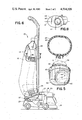
- FIG. 5 is an end elevation of the dirt box.
- FIG. 6 is a side elevation of the cleaner seen in FIG. 1, with the fabric bag partly broken away to show the fill tube and part of the paper filter bag.
- FIG. 7 is a view taken on line 7--7 in FIG. 6.
- FIG. 8 is a view taken along line 8--8 of FIG. 3.
- FIGS. 1 and 6 Shown in FIGS. 1 and 6 is an upright vacuum cleaner 10 provided with a fabric filter bag 12 and a disposable paper filter bag 14.
- the cleaner includes a rug-cleaning nozzle 16, a motor housing 18 and an exhaust fan outlet 20.
- a vacuum cleaner fan (not shown) sucks dirt into the cleaner through the rug cleaning nozzle and then blows the dirt-laden air through the outlet tube 20 to the inlet neck 21 of a dirt box 22.
- the bottom end of the fabric bag 12 is attached to the top of the dirt box 22.
- the dirt box 22 will be more fully described below. As has been done with conventional dirt boxes, see for example U.S. Pat. No.
- the dirt box of the present invention may exhaust into a fill tube 24 which is hung within the fabric bag 12 and feeds the dirt-laden air to the top end of the paper filter bag 14.
- the filter bag 14 is removable and replaceable in a known manner, as described for example in the aforesaid patent, a zipper (not shown) being provided at the rear side of the fabric bag 12 so that it may be opened and reclosed for such purposes.
- the fill tube 24 remains in place during removal and replacement of the paper bag.
- the fill tube is connected to the paper bag by a molded connector assembly 26. The details of such connection form no part of the present invention, but may be as described in the aforesaid patent.
- the dirt box is intended to act as a separator to collect larger, heavier particles before they enter the filter bags.
- the dirt box 22 of the invention is of a novel design which eliminates a removable bottom and, instead, provides a bowl-like ovoid structure which has a superior centrifugal swirling action that minimizes turbulence and loss of air wattage.
- the dirt box can be readily emptied by being partially disconnected, tilted, and emptied through its intake.
- the dirt box includes a top wall 28 which slants downwardly in the lengthwise direction in the normal position of use of the box, such normal position being shown in solid lines in all of the figures.
- a side wall 30 is elliptical in shape where it is adjacent the top wall 28.
- the side wall 30 is faired into a permanently closed bottom wall 32 which generally has the shape of a somewhat elongated bowl. These walls define the dirt box chamber 34.
- the inlet neck 21 opens through the bowl-shaped bottom wall 32 into the dirt box chamber 34. As best seen from FIG. 2, such opening of the neck 21 through the bottom wall into the chamber 34 is in the lengthwise direction. As best seen in FIG. 4, such opening of the neck 21 into the chamber 34 is below the front end of the top wall 28 and is spaced downwardly from such end of the top wall by the elliptical portion of the side wall 30 which is adjacent the top wall 28.
- the inlet neck 21 is aimed in a lengthwise direction, but as seen, for example, in FIG. 5, the center or central axis C of the inlet neck is aimed to one side of the center of chamber 34. As best seen in FIGS. 3-5, the center of the inlet neck is aimed convergently toward the downwardly slanting top wall 28.
- An outlet port in the top wall 28 is defined by outlet collar 36.
- the center or central axis D of the outlet port (such axis being seen on end as a point in FIG. 8) is longitudinally offset from the center of the top wall, such offsetting being toward the front end of the top wall.
- the dirt box 22 is formed in two parts which are welded together after being molded separately.
- the collar 36, top wall 28, and the elliptical upper portion of side wall 30 which is adjacent the top wall all are molded as a unitary part provided around its bottom edge with a suitable bead 31 and groove to receive the upper edge of the other unitary molded part, the latter comprising the remaining portions of side wall 30, the bowl-shaped bottom wall 32, and the inlet neck 21.
- the fabric bag is provided with the conventional elastic band (helical spring or elasticized cord, not seen) sewn into a hem around the bag mouth, and this may be stretched over a retaining flange 29 formed at the edge of the top wall 28, so that the bag mouth is engaged around the upper elliptical portion of side wall 30 in the groove-like channel between flange 29 and bead 31.
- a flexible elastomeric collar 27 (FIGS. 1 and 6) may be provided to engage over the flange 29 and bead 31 to cover the just-described joinder of the fabric bag and dirt box.
- the elliptical shape of side wall 30 is divided into symmetrical lateral halves by the imaginary plane of symmetry E which passes through the long axis of the elliptical shape, and is divided into symmetrical front and back halves by the imaginary plane of symmetry F which passes through the short axis of the elliptical shape.
- the outlet port formed by outlet collar 36 is symmetrical with respect to the plane E, while the central axis D of the outlet port is offset forwardly of the plane F but generally parallel thereto.
- the central axis C of the inlet neck is not normal to plane F but, rather, forms an acute angle a therewith.
- the central axis C (seen on end as a point) is offset from the plane E, but is generally parallel thereto.
- the fill tube 24 comprises a helically ridged and grooved, flexible vinyl tube whose bottom end engages the threading 38 on outlet collar 36 and whose top end engages threading (not seen) on molded connector assembly 26.
- the top end engagement is secured by a tie clamp 40 which accomplishes a seal of the tube 24 to the threading on the connector assembly 26.
- no tie clamp is required for the bottom connection of the fill tube.
- the threading 38 is formed with a relatively rounded upper crest edge 42 (say 0.06 inch radius), but a sharp lower crest edge 41 (say, 0.01 inch radius or less). This arrangement has been found to provide an effective and reliable seal between the fill tube 24 and the outlet collar without use of any tie clamp at such connection, with resulting cost saving.
- the exhaust fan outlet tube 20 is provided with the male portion of a bayonet connection, and suitable bayonet connector slots 42 are provided on the female connector side associated with the inlet neck 21.
- the male end of the exhaust fan outlet tube 20 may seal against an O-ring (not shown) which is seated against the flange stop 44.
- the inlet neck 21, together with the dirt box proper is bodily twisted to release the bayonet connection between the inlet neck 21 and exhaust fan outlet tube 20. To accomplish this, it is not necessary to disconnect the dirt box from the fabric bag 12 nor from the fill tube 24. After the bayonet connection is released, the neck 21 is tilted downwardly along with the rest of the dirt box, as shown in phantom in FIG. 6, in which position the chamber 34 may be readily emptied. The bayonet connection is then re-established for subsequent operation of the cleaner.
Abstract
Description
Claims (5)
Priority Applications (1)
| Application Number | Priority Date | Filing Date | Title |
|---|---|---|---|
| US06/614,261 US4514199A (en) | 1984-05-25 | 1984-05-25 | Vacuum cleaner dirt box |
Applications Claiming Priority (1)
| Application Number | Priority Date | Filing Date | Title |
|---|---|---|---|
| US06/614,261 US4514199A (en) | 1984-05-25 | 1984-05-25 | Vacuum cleaner dirt box |
Publications (1)
| Publication Number | Publication Date |
|---|---|
| US4514199A true US4514199A (en) | 1985-04-30 |
Family
ID=24460498
Family Applications (1)
| Application Number | Title | Priority Date | Filing Date |
|---|---|---|---|
| US06/614,261 Expired - Lifetime US4514199A (en) | 1984-05-25 | 1984-05-25 | Vacuum cleaner dirt box |
Country Status (1)
| Country | Link |
|---|---|
| US (1) | US4514199A (en) |
Cited By (10)
| Publication number | Priority date | Publication date | Assignee | Title |
|---|---|---|---|---|
| GB2214104A (en) * | 1988-01-19 | 1989-08-31 | Electrolux Ab | Separator for vacuum cleaner |
| US4877432A (en) * | 1988-06-17 | 1989-10-31 | The Scott Fetzer Company | Disposable dust bag for vacuum cleaners and the like |
| WO1990003214A1 (en) * | 1988-09-26 | 1990-04-05 | The Scott Fetzer Company | Vacuum cleaner filter bag assembly |
| WO1991000707A1 (en) * | 1989-07-11 | 1991-01-24 | The Scott Fetzer Company | Disposable dust bag for vacuum cleaners and the like |
| US5057131A (en) * | 1988-09-26 | 1991-10-15 | The Scott Fetzer Company | Vacuum cleaner filter bag assembly |
| US5064455A (en) * | 1988-06-17 | 1991-11-12 | The Scott Fetzer Company | Disposable dust bag for vacuum cleaners and the like |
| US5092915A (en) * | 1988-06-17 | 1992-03-03 | The Scott Fetzer Company | Disposable dust bag for vacuum cleaners and the like |
| GB2266065A (en) * | 1992-04-06 | 1993-10-20 | Arthur John Arnold | Vacuum particle collector |
| US6348078B1 (en) | 2000-05-22 | 2002-02-19 | Jerry Crismore | Vacuum cleaner output duct extension |
| US6574827B2 (en) | 2000-01-31 | 2003-06-10 | Matsushita Electric Industrial Co., Ltd. | Electric vacuum cleaner having increased stability and resistance against inadvertant falling over of the vacuum cleaner |
Citations (8)
| Publication number | Priority date | Publication date | Assignee | Title |
|---|---|---|---|---|
| US1983175A (en) * | 1930-07-11 | 1934-12-04 | Ind Improvements Inc | Suction cleaner |
| US2133141A (en) * | 1936-12-05 | 1938-10-11 | Gen Electric | Vacuum cleaner |
| US2537523A (en) * | 1948-04-09 | 1951-01-09 | Clements A Frost | Portable vacuum cleaner |
| US2583054A (en) * | 1946-04-22 | 1952-01-22 | James B Kirby | Automatic nozzle adjusting device for vacuum cleaners |
| US2823411A (en) * | 1953-06-22 | 1958-02-18 | James B Kirby | Vacuum cleaner |
| US3468563A (en) * | 1966-08-10 | 1969-09-23 | Vallourec | Separable joint for pipes |
| US3608333A (en) * | 1968-06-20 | 1971-09-28 | Bison Mfg Co Inc | Vacuum cleaner and power unit |
| US4262384A (en) * | 1980-01-25 | 1981-04-21 | The Scott & Fetzer Company | Vacuum cleaner bag assembly |
-
1984
- 1984-05-25 US US06/614,261 patent/US4514199A/en not_active Expired - Lifetime
Patent Citations (8)
| Publication number | Priority date | Publication date | Assignee | Title |
|---|---|---|---|---|
| US1983175A (en) * | 1930-07-11 | 1934-12-04 | Ind Improvements Inc | Suction cleaner |
| US2133141A (en) * | 1936-12-05 | 1938-10-11 | Gen Electric | Vacuum cleaner |
| US2583054A (en) * | 1946-04-22 | 1952-01-22 | James B Kirby | Automatic nozzle adjusting device for vacuum cleaners |
| US2537523A (en) * | 1948-04-09 | 1951-01-09 | Clements A Frost | Portable vacuum cleaner |
| US2823411A (en) * | 1953-06-22 | 1958-02-18 | James B Kirby | Vacuum cleaner |
| US3468563A (en) * | 1966-08-10 | 1969-09-23 | Vallourec | Separable joint for pipes |
| US3608333A (en) * | 1968-06-20 | 1971-09-28 | Bison Mfg Co Inc | Vacuum cleaner and power unit |
| US4262384A (en) * | 1980-01-25 | 1981-04-21 | The Scott & Fetzer Company | Vacuum cleaner bag assembly |
Cited By (14)
| Publication number | Priority date | Publication date | Assignee | Title |
|---|---|---|---|---|
| GB2214104A (en) * | 1988-01-19 | 1989-08-31 | Electrolux Ab | Separator for vacuum cleaner |
| US5092915A (en) * | 1988-06-17 | 1992-03-03 | The Scott Fetzer Company | Disposable dust bag for vacuum cleaners and the like |
| US4877432A (en) * | 1988-06-17 | 1989-10-31 | The Scott Fetzer Company | Disposable dust bag for vacuum cleaners and the like |
| US5064455A (en) * | 1988-06-17 | 1991-11-12 | The Scott Fetzer Company | Disposable dust bag for vacuum cleaners and the like |
| WO1990003214A1 (en) * | 1988-09-26 | 1990-04-05 | The Scott Fetzer Company | Vacuum cleaner filter bag assembly |
| US5057131A (en) * | 1988-09-26 | 1991-10-15 | The Scott Fetzer Company | Vacuum cleaner filter bag assembly |
| WO1991000707A1 (en) * | 1989-07-11 | 1991-01-24 | The Scott Fetzer Company | Disposable dust bag for vacuum cleaners and the like |
| AU633948B2 (en) * | 1989-07-11 | 1993-02-11 | Scott Fetzer Company, The | Disposable dust bag for vacuum cleaners and the like |
| GB2266065A (en) * | 1992-04-06 | 1993-10-20 | Arthur John Arnold | Vacuum particle collector |
| GB2266065B (en) * | 1992-04-06 | 1995-10-25 | Arthur John Arnold | Vacuum particle collector |
| US6574827B2 (en) | 2000-01-31 | 2003-06-10 | Matsushita Electric Industrial Co., Ltd. | Electric vacuum cleaner having increased stability and resistance against inadvertant falling over of the vacuum cleaner |
| US6588051B2 (en) * | 2000-01-31 | 2003-07-08 | Matsushita Electric Industrial Co., Ltd. | Electric vacuum cleaner having a structure for facilitating the manufacturability thereof |
| US6678916B2 (en) | 2000-01-31 | 2004-01-20 | Matsushita Electric Industrial Co., Ltd. | Vacuum cleaner hose unit having a hose fitting with a coupling protrusion |
| US6348078B1 (en) | 2000-05-22 | 2002-02-19 | Jerry Crismore | Vacuum cleaner output duct extension |
Similar Documents
| Publication | Publication Date | Title |
|---|---|---|
| US11910992B2 (en) | Handheld vacuum cleaner | |
| US6432154B2 (en) | Cyclone dust collecting apparatus for a vacuum cleaner | |
| CA2539689C (en) | Cyclone dust-collecting device and vacuum cleaner having the same | |
| EP0489565B1 (en) | Shroud and cyclonic cleaning apparatus incorporating same | |
| US7395579B2 (en) | Cyclone dust collecting device and vacuum cleaner having the same | |
| AU2007201420B2 (en) | Dust collector of vacuum cleaner | |
| US4262384A (en) | Vacuum cleaner bag assembly | |
| US4514199A (en) | Vacuum cleaner dirt box | |
| US7479172B2 (en) | Cyclonic separators for suction cleaners | |
| US20050252179A1 (en) | Multi cyclone vessel dust collecting apparatus for vacuum cleaner | |
| MXPA00001895A (en) | Cyclonic dirt cup assembly. | |
| US6772473B2 (en) | Waste collecting container for vacuum cleaner | |
| US20040040270A1 (en) | Cyclonic vacuum cleaner | |
| JPH11511340A (en) | Pickup head for vacuum cleaner | |
| AU2003255215B2 (en) | Handle Tube and Cyclone Vacuum Cleaner Equipped with the Same | |
| US20030167591A1 (en) | Vacuum cleaner having cyclone dust collecting apparatus | |
| US7181803B2 (en) | Dual filter, upright vacuum cleaner with detachable hose | |
| JP2006508725A (en) | Arrangement of dust separator and collector for vacuum cleaner | |
| US4469498A (en) | Dirt interceptor filter bag mount for vacuum cleaner | |
| EP3009059A1 (en) | Cleaner | |
| US10376116B2 (en) | Vacuum cleaner | |
| KR200342947Y1 (en) | Cyclone dust-collecting apparatus for a vacuum cleaner | |
| JPS6250140B2 (en) | ||
| US1855672A (en) | Dirt-receiving receptacle for vacuum cleaners | |
| KR101065954B1 (en) | Vacuunm cleaner |
Legal Events
| Date | Code | Title | Description |
|---|---|---|---|
| AS | Assignment |
Owner name: SCOTT & FETZER COMPANY, THE AN OH CORP. Free format text: ASSIGNMENT OF ASSIGNORS INTEREST.;ASSIGNORS:FORD, ROGER S.;SHIE, HERMAN J. III;BAIRD, THOMAS E. SR;REEL/FRAME:004266/0120 Effective date: 19840521 |
|
| STCF | Information on status: patent grant |
Free format text: PATENTED CASE |
|
| AS | Assignment |
Owner name: SCOTT FETZER COMPANY, THE, A CORP. OF DE. Free format text: ASSIGNMENT OF ASSIGNORS INTEREST. ASSIGNMENT OF ASSIGNORS INTEREST, EFFECTIVE DECEMBER 31, 1986.;ASSIGNOR:SCOTT & FETZER COMPANY, THE, A OH. CORP.;REEL/FRAME:004717/0286 Effective date: 19861126 |
|
| FEPP | Fee payment procedure |
Free format text: PAYOR NUMBER ASSIGNED (ORIGINAL EVENT CODE: ASPN); ENTITY STATUS OF PATENT OWNER: LARGE ENTITY |
|
| FPAY | Fee payment |
Year of fee payment: 4 |
|
| FEPP | Fee payment procedure |
Free format text: PAYER NUMBER DE-ASSIGNED (ORIGINAL EVENT CODE: RMPN); ENTITY STATUS OF PATENT OWNER: LARGE ENTITY Free format text: PAYOR NUMBER ASSIGNED (ORIGINAL EVENT CODE: ASPN); ENTITY STATUS OF PATENT OWNER: LARGE ENTITY |
|
| FPAY | Fee payment |
Year of fee payment: 8 |
|
| FEPP | Fee payment procedure |
Free format text: PAYER NUMBER DE-ASSIGNED (ORIGINAL EVENT CODE: RMPN); ENTITY STATUS OF PATENT OWNER: LARGE ENTITY Free format text: PAYOR NUMBER ASSIGNED (ORIGINAL EVENT CODE: ASPN); ENTITY STATUS OF PATENT OWNER: LARGE ENTITY |
|
| FPAY | Fee payment |
Year of fee payment: 12 |