US4516791A - Safety ski binding - Google Patents
Safety ski binding Download PDFInfo
- Publication number
- US4516791A US4516791A US06/479,407 US47940783A US4516791A US 4516791 A US4516791 A US 4516791A US 47940783 A US47940783 A US 47940783A US 4516791 A US4516791 A US 4516791A
- Authority
- US
- United States
- Prior art keywords
- ski
- pressure
- pin
- sole
- upper side
- Prior art date
- Legal status (The legal status is an assumption and is not a legal conclusion. Google has not performed a legal analysis and makes no representation as to the accuracy of the status listed.)
- Expired - Fee Related
Links
Images


Classifications
-
- A—HUMAN NECESSITIES
- A63—SPORTS; GAMES; AMUSEMENTS
- A63C—SKATES; SKIS; ROLLER SKATES; DESIGN OR LAYOUT OF COURTS, RINKS OR THE LIKE
- A63C9/00—Ski bindings
- A63C9/08—Ski bindings yieldable or self-releasing in the event of an accident, i.e. safety bindings
- A63C9/088—Ski bindings yieldable or self-releasing in the event of an accident, i.e. safety bindings with electronically controlled locking devices
Definitions
- the invention relates to a safety ski binding and, more particularly, to a binding having two jaws which hold the ski boot, preferably a releasable heel holder and a holding jaw, a sensing system for detecting a force which acts onto the ski boot upwardly or downwardly, transversely and, if desired, longitudinally, wherein signals generated by the sensing system are processed in a control circuit which, if pregiven limit values are exceeded, emits a release signal to the releasable jaw.
- the safety ski binding which is disclosed therein includes a front jaw and a heel holder which is pivotal about a transverse axis (see FIGS. 1 to 3).
- a transverse axis which is above the leg of the boot and in the longitudinal direction of the ski approximately intermediate the front and the rear boot-leg edge.
- a first pressure sensor is provided between the tip of the sole of the boot and its point of contact on the holding jaw, and further pressure sensors are arranged below the sole of the boot and between a sole down-holding means which is arranged on the heel holder and the upper side of the boot sole and the stepping spur of the heel holder.
- either one or two sole holders are provided which can be swung up or out against a spring force. Even though the release force can be adjusted by changing the initial tension of the spring, it is not possible in such a binding to detect in a sufficient manner all forces which endanger the leg of the skier.
- a purpose of the invention is therefore to design a sensing device of the above-mentioned type in which detection of all dangerous forces which act onto the leg of the skier is possible.
- the set purpose is attained inventively by providing on the holding jaw two sole holders which hold the ski boot sole from above and from the side and which are supported slightly pivotally on a pin which extends perpendicular to the upper side of the ski and is itself slightly pivotally supported by a further pin which extends transversely to the longitudinal direction of the ski and parallel to the upper side of the ski.
- the sole holders are each provided with a respective pressure Piston which can act on either a differential pressure cell or a respective absolute pressure cell, and at least one of the sole holders has in a region which does not face the ski boot a pressure pin which can act on a further absolute pressure cell.
- a stepping plate is supported slightly pivotally on the further pin which extends transversely to the longitudinal axis of the ski, parallel to and is spaced from the upper side of the ski.
- the stepping plate carries at its end region which does not face the ski boot a pressure pin which can also act on the further absolute pressure cell.
- the inventive sensing device permits detection of the forces which occur in the region of the holding jaw.
- absolute pressure cells In the case that absolute pressure cells are provided, it permits a detection of forces which act transversely to the longitudinal axis of the ski and longitudinally of the ski through subtraction or addition of the signals which correspond to the measured values and are produced by the absolute pressure cells which are arranged on the sole holders.
- the pressure pin which is arranged on the sole holder or the pressure pin on the stepping plate acts on the further absolute pressure cell.
- a differential pressure cell which cooperates with the two pressure pistons arranged on the sole holders can be used to detect the forces which act transversely to the longitudinal axis of the ski.
- An advantageous development of the invention includes the pressure pin of the sole holder and the pressure pin of the stepping plate acting onto respective membranes of a closed sensing chamber filled with pressure fluid, which membranes extend approximately parallel to the upper side of the ski, the pressure pin of the sole holder acting from above and the pressure pin of the stepping plate acting from below, and a further surface of the sensing chamber being defined by the membrane of the further absolute pressure cell.
- a structurally simple arrangement is provided for transferring forces which act vertically onto the sole holder or onto the stepping plate in the area of the ball of the foot to the absolute pressure cell. The resulting force is measured as an absolute force, and a signal corresponding to this measured force is produced by the absolute pressure cell and processed in the control circuit.
- the pin which extends perpendicular to the upper side of the ski is held in a bearing member which is supported on a further pin which extends parallel to the upper side of the ski, transversely to the longitudinal axis of the ski, and is held by means of its end regions in fastening plates of a ski-fixed housing which carries the pressure cells.
- the stepping plate has two holding plates which extend perpendicular to the upper side of the ski and parallel to the longitudinal axis of the ski, respectively extend into the area between the bearing member and a respective one of the fastening plates of the housing, and by means of which the stepping plate is pivotally supported on the pin.
- each sole holder in a region which does not face the ski boot, a holding arm on which a respective one of the pressure pistons is provided, each piston extending inwardly toward the longitudinal axis of the ski and engaging a respective membrane which defines one side of a respective chamber filled with pressure fluid, a further side of each such chamber being formed either by a respective one of the membranes of the differential pressure cell or by the membrane of a respective one of the two absolute pressure cells, which are arranged in alignment with one another.
- FIG. 1 is a longitudinal sectional side view of an exemplary embodiment of a jaw embodying the invention
- FIG. 2 is a top view of the jaw of FIG. 1;
- FIG. 3 is a sectional rear view taken along the line III--III of FIG. 2;
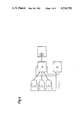
- FIG. 4 is a block diagram for a control unit for controlling a releasable jaw embodying the present invention.
- FIG. 5 is a schematic diagram of an exemplary circuit implementing different parts of the control unit of FIG. 4.
- a housing 2 is secured on a ski 1.
- the housing 2 can also be connected fixedly to the ski 1 with the interpositioning of a conventional base plate (not illustrated).
- Three pressure cells 3, 4 and 5 are installed in the housing 2, for example by being screwed in.
- the pressure cell 3 is hereby provided in the region of the housing 2 which is nearest the tip of the ski, and the two pressure cells 4 and 5 are installed in longitudinal and vertical alignment with one another approximately in the center of the jaw.
- the pressure cells 3, 4 and 5 are absolute pressure cells, as compared to differential pressure cells, the pressure cell 3 being provided for detecting forces which act in a vertical direction, and the pressure cells 4 and 5 being provided for detecting forces which act in horizontal directions laterally and longitudinally of the ski, the directions of these forces being defined with reference to the plane of the top surface of the ski.
- pressure cells e.g. pressure cells manufactured by the company Druckund Kraftmesstechnik H. W. Keller, CH 8404 Winterthur (Switzerland), model nos. PA-10, PR-10 or PA-14.
- the pressure cell 3 is positioned in the housing so that its steel membrane 3a is perpendicular to the upper side of the ski and to the longitudinal axis of the ski.
- the steel membrane 3a forms one wall of an elongate, closed sensing chamber 25 which is filled with a substantially incompressible pressure fluid, extends substantially parallel to the steel membrane 3a, and has bottom and top walls which extend parallel to the upper side of the ski and are formed by respective flexible membranes 6 and 7.
- the lower membrane 6 can be flexed inwardly by a pressure pin 8 secured on an extension 9a of a stepping plate 9, and the upper membrane 7 can be flexed inwardly by a pressure pin 15 which is secured on a sole holder 13.
- the stepping plate 9 forms, together with its extension 9a, a flat plate, the end region 9b of the stepping plate 9, which is remote from the extension 9a, being adapted to support the ball region of a ski boot sole.
- the center section 9c of the stepping plate 9, which is adjacent the stepping region 9b, carries two holding plates 9d (FIG. 3) which are arranged symmetrically with respect to the longitudinal axis of the ski and extend at a right angle with respect to the upper side of the ski.
- Two fastening plates 2a provided on the housing 2 overlap the two holding plates 9d of the stepping plate 9.
- a pin 11 which extends parallel to the upper side of the ski and transversely with respect to the longitudinal axis of the ski is held by means of its end areas in the fastening plates 2a of the housing 2.
- the pin 11 also extends through the holding plates 9d of the stepping plate 9, whereby a pivotal support of the stepping plate 9 on the pin 11 is effected, and between the underside of the stepping plate 9 and the upper side of the ski 1 there exists a small space or vertical clearance.
- the stepping plate 9 is permitted to carry out a limited swivelling movement about the pin 11. If no ski boot is inserted into the jaw, so that the jaw is in the position illustrated in FIG.
- the stepping plate 9 is held in a position which is generally parallel to the upper side of the ski, on the one hand by the pressure pin 8 which engages the flexible membrane 6 of the sensing chamber 25 and on the other hand by an elastic sleeve 12 which surrounds the stepping plate 9 at least in the region thereof which is not covered by the housing 2.
- the sleeve 12 also prevents a penetration of snow and dirt into the region which exists between the stepping plate 9 and the upper side of the ski.
- a bearing member 10 is pivotally supported on the pin 11 at a distance from the upper side of the stepping plate 9 and in the present exemplary embodiment is designed as a square-shaped block. The function of the bearing member 10 will be discussed below.
- the pressure pin 15 which engages the upper membrane 7 of the sensing chamber 25 is secured on an arm 13a of the sole holder 13.
- Each of the sole holders 13 and 14 has a region which at least partially covers the bearing member 10 from above, which regions overlap one another. By means of these overlapping regions of the two sole holders 13 and 14, they are pivotally supported on a common vertical axle which is constructed as a further pin 16.
- the pin 16 is supported by the bearing member 10 and extends perpendicular to the upper side of the ski.
- Each of the sole holders 13 and 14 has a respective holding arm 13c and 14c which carries a respective pressure piston 17 and 18.
- the two pressure pistons 17 and 18 extend from the associated holding arm 13c or 14c of the sole holder 13 or 14 inwardly toward the longitudinal axis of the ski in a direction generally parallel to the upper side of the ski and at a right angel with respect to the longitudinal axis of the ski.
- Each of the pressure pistons 17 and 18 engages a respective flexible membrane 21 and 22, which membranes 21 and 22 each define one surface of a respective sensing chamber 19 or 20 which is filled with a substantially incompressible pressure fluid.
- a surface of each chamber 19 and 20 remote from the pressure piston 17 or 18 is formed by a membrane of one of the two pressure cells 4 and 5.
- the pressure cells are preferably piezoelectric, temperature-compensated pressure cells.
- the voltage which is produced by the piezoelectric crystal is transmitted to and further processed (amplified, filtered, etc.) in a control circuit, which can be located in the front jaw or in the not-illustrated heel holder of the ski binding.
- a release signal is produced by the control circuit and causes a release of a locking mechanism which is provided in the not-illustrated heel holder and is for example controlled by means of an electromagnet, thereby effecting a release of the ski boot from the binding at the heel holder.
- the voltage supply for the control circuit and the release mechanism is provided by batteries which are preferably disposed in the heel holder or in the ski. Since the heel holder is not a part of the subject matter of the present invention, its design is not discussed in greater detail. Of course, the heel holder is also preferably equipped with force-measuring sensors, so that the locking mechanism is also released to free the ski boot if the boot heel transmits impermissibly high forces to the heel holder.
- the skier's weight When the ski boot is inserted into the binding, the skier's weight, through the ski boot, exerts a force on the stepping plate 9. This force is thereby transmitted to the fluid in chamber 25 and thus to the pressure cell 3 and is considered by the control circuit in comparison to the stored body weight of the skier. Due to the conventional forward pressure normally exerted on the boot by the heel holder, the sole holders 13 and 14 pivot slightly and a certain force is thereby applied by the sole holders 13 and 14 to the fluid in chambers 19 and 20 and thus to the pressure cells 4 and 5, producing a signal which is also considered by the control circuit.
- the sole holders 13 and 14 both pivot slightly further outwardly about the pin 16, which causes the force which is transmitted by the pressure pistons 17 and 18 to the pressure fluid in the chambers 19 and 20 and thus to the pressure cells 4 and 5 to be increased. If only one of the two sole holders 13 and 14 is urged by the boot in a horizontal direction, then only the pressure cell 4 or 5 which is associated with the respective sole holder 13 or 14 is subjected to an increased force. By adding up in the control circuit the signals which represent the two measured variables and are produced by the two pressure cells 4 and 5, the forces which act in the longitudinal direction of the ski are determined.
- the control circuit determines whether they exceed pregiven threshold values and thus whether to produce a release signal to the heel holder locking mechanism.
- the signal which is produced by the pressure cell 3 and fed to the control circuit is increased and is considered when determining whether to produce a release signal.
- a differential pressure cell can be used, the two membranes of which are associated with the sole holders 13 and 14, so that measuring of the difference in the forces transmitted by the sole holders 13 and 14 onto the membranes is possible. Forces which act in the longitudinal direction of the ski can be detected by a pressure cell of this type.
- FIG. 4 illustrates a block diagram including a power supply unit 30 connected to the pressure sensors 3, 4, 5 and to the control unit 31.
- the pressure sensors 3, 4, 5 are connected to the control unit 31, which itself is connected to a solenoid 32 representing the locking mechanism of heel holder 33.
- FIG. 5 illustrates an exemplary circuit for the control unit 31.
- the piezoelectric pressure cells 3, 4, 5 are formed by bridge circuits of resistance strain sensors 40.
- the output signals of the pressure cells 3, 4, 5 are amplified by amplifiers V3, V4, V5.
- the output signals of the amplifiers V4 and V5 are fed to an integrator V1 for adding up and to an integrator V2 for substraction respectively.
- the output signal of the integrator V1 is fed to a rectifier 34, which includes two amplifiers V6 and V7, for building the absolute value.
- the output signal of the amplifier V3 is fed to an integrator V8.
- the output signals of the rectifier 34, the integrator V2 and the integrator V8 are summed up in a summing amplifier V9 and are then fed to an amplifier V10 which acts as a threshold switch, the switching threshold of which is determined by variable resistors R5, R6 and R7, which resistors are provided in a storage unit 35 and have values corresponding to user-specific data.
- the output driver 36 which is driven by the threshold switch is formed by a thyristor T1 which is connected to and controls the solenoid 32.
- the R-C network comprising resistor R81 and capacitor C1 (feedback path of the integrator V1), resistor R2 and capacitor C2 (feedback path of the integrator V2), resistor R8 and capacitor C8 (feedback path of the integrator V8), and resistor R9 and Capacitor C9 are provided in an exchangeable program storage 37 which is selected to correspond to the ability group of the particular skier, for example a beginning or sport skier, the signal amplification and dynamic release behaviour being predetermined by the particular component values selected so as to correspond to the appropriate ability group.
- control unit 31 For a more detailed description of the control unit 31 reference is made to the U.S. application Ser. No. 315,671, which is an earlier application and which includes a control unit very similar to that described above.
Landscapes
- Force Measurement Appropriate To Specific Purposes (AREA)
- Footwear And Its Accessory, Manufacturing Method And Apparatuses (AREA)
Abstract
Description
Claims (5)
Applications Claiming Priority (2)
| Application Number | Priority Date | Filing Date | Title |
|---|---|---|---|
| AT0123082A AT372866B (en) | 1982-03-30 | 1982-03-30 | SAFETY SKI BINDING |
| AT1230/82 | 1982-03-30 |
Publications (1)
| Publication Number | Publication Date |
|---|---|
| US4516791A true US4516791A (en) | 1985-05-14 |
Family
ID=3509416
Family Applications (1)
| Application Number | Title | Priority Date | Filing Date |
|---|---|---|---|
| US06/479,407 Expired - Fee Related US4516791A (en) | 1982-03-30 | 1983-03-28 | Safety ski binding |
Country Status (5)
| Country | Link |
|---|---|
| US (1) | US4516791A (en) |
| EP (1) | EP0091574B1 (en) |
| JP (1) | JPS58178237A (en) |
| AT (1) | AT372866B (en) |
| DE (1) | DE3360201D1 (en) |
Cited By (4)
| Publication number | Priority date | Publication date | Assignee | Title |
|---|---|---|---|---|
| US5294144A (en) * | 1991-09-10 | 1994-03-15 | Marker Deutschland Gmbh | Hydraulic ski binding incorporating electronically-controlled bypass |
| US5775715A (en) * | 1995-08-01 | 1998-07-07 | K-2 Corporation | Piezoelectric damper for a board such as a snow ski or snowboard |
| US6095547A (en) * | 1995-08-01 | 2000-08-01 | K-2 Corporation | Active piezoelectric damper for a snow ski or snowboard |
| US20070090626A1 (en) * | 2005-10-20 | 2007-04-26 | Salomon S.A. | Safety binding |
Citations (5)
| Publication number | Priority date | Publication date | Assignee | Title |
|---|---|---|---|---|
| US3919563A (en) * | 1973-04-10 | 1975-11-11 | Anvar | Controllably self-releasable safety fastener and method of unlocking same |
| US4311321A (en) * | 1978-07-11 | 1982-01-19 | Tmc Corporation | Ski binding |
| US4385773A (en) * | 1979-11-30 | 1983-05-31 | Geze Gmbh | Ski safety binding |
| US4444411A (en) * | 1981-05-04 | 1984-04-24 | Tmc Corporation | Safety ski binding |
| US4463968A (en) * | 1980-06-24 | 1984-08-07 | The Regents Of The University Of California | Method for programmed release in ski bindings |
Family Cites Families (7)
| Publication number | Priority date | Publication date | Assignee | Title |
|---|---|---|---|---|
| FR89533E (en) * | 1965-08-25 | |||
| AT324903B (en) * | 1971-11-25 | 1975-09-25 | Smolka & Co Wiener Metall | SKI BINDING |
| FR2218913B1 (en) * | 1973-02-22 | 1978-01-06 | Ver Baubeschlag Gretsch Co | |
| FR2309257A1 (en) * | 1975-04-30 | 1976-11-26 | Salomon & Fils F | SAFETY BINDING FOR SKI |
| FR2413915A1 (en) * | 1978-01-10 | 1979-08-03 | Beyl Jean Joseph Alfred | Safety release binding for ski - has spring follower held against cam slots with release effected by combined horizontal and vertical movement |
| DE2901110A1 (en) * | 1979-01-12 | 1980-07-31 | U V G Unternehmensberatungs Un | Front jaw for safety ski bindings - has one piece angled section fitted to common turning axis to swivel sideways against spring tension |
| DE2925375A1 (en) * | 1979-06-22 | 1981-01-29 | Marker Hannes | ELECTRONIC SAFETY SKI BINDING |
-
1982
- 1982-03-30 AT AT0123082A patent/AT372866B/en not_active IP Right Cessation
-
1983
- 1983-03-19 DE DE8383102744T patent/DE3360201D1/en not_active Expired
- 1983-03-19 EP EP83102744A patent/EP0091574B1/en not_active Expired
- 1983-03-28 US US06/479,407 patent/US4516791A/en not_active Expired - Fee Related
- 1983-03-28 JP JP58050575A patent/JPS58178237A/en active Granted
Patent Citations (5)
| Publication number | Priority date | Publication date | Assignee | Title |
|---|---|---|---|---|
| US3919563A (en) * | 1973-04-10 | 1975-11-11 | Anvar | Controllably self-releasable safety fastener and method of unlocking same |
| US4311321A (en) * | 1978-07-11 | 1982-01-19 | Tmc Corporation | Ski binding |
| US4385773A (en) * | 1979-11-30 | 1983-05-31 | Geze Gmbh | Ski safety binding |
| US4463968A (en) * | 1980-06-24 | 1984-08-07 | The Regents Of The University Of California | Method for programmed release in ski bindings |
| US4444411A (en) * | 1981-05-04 | 1984-04-24 | Tmc Corporation | Safety ski binding |
Cited By (5)
| Publication number | Priority date | Publication date | Assignee | Title |
|---|---|---|---|---|
| US5294144A (en) * | 1991-09-10 | 1994-03-15 | Marker Deutschland Gmbh | Hydraulic ski binding incorporating electronically-controlled bypass |
| US5775715A (en) * | 1995-08-01 | 1998-07-07 | K-2 Corporation | Piezoelectric damper for a board such as a snow ski or snowboard |
| US6095547A (en) * | 1995-08-01 | 2000-08-01 | K-2 Corporation | Active piezoelectric damper for a snow ski or snowboard |
| US20070090626A1 (en) * | 2005-10-20 | 2007-04-26 | Salomon S.A. | Safety binding |
| US7438307B2 (en) * | 2005-10-20 | 2008-10-21 | Salomon S.A. | Safety binding |
Also Published As
| Publication number | Publication date |
|---|---|
| EP0091574A1 (en) | 1983-10-19 |
| DE3360201D1 (en) | 1985-06-27 |
| AT372866B (en) | 1983-11-25 |
| ATA123082A (en) | 1983-04-15 |
| JPH0252973B2 (en) | 1990-11-15 |
| EP0091574B1 (en) | 1985-05-22 |
| JPS58178237A (en) | 1983-10-19 |
Similar Documents
| Publication | Publication Date | Title |
|---|---|---|
| US3610650A (en) | Ski boot holding clamp | |
| US4694684A (en) | Dynamic balancing for skis | |
| US4516792A (en) | Laterally releasable toe unit for a ski safety binding | |
| US4385773A (en) | Ski safety binding | |
| US4516791A (en) | Safety ski binding | |
| US4545598A (en) | Safety ski binding | |
| US4784404A (en) | Safety ski binding capable of releasing sideways | |
| US4465295A (en) | Dynamic ski boot positioning apparatus | |
| US5687982A (en) | Element and assembly for retaining a boot on a gliding board | |
| US5566966A (en) | Device for modifying the pressure distribution of a ski along its sliding surface | |
| ATE165989T1 (en) | BINDINGS FOR ALPINE SKI | |
| US4600213A (en) | Safety ski-binding having a sole plate | |
| US5639108A (en) | Boot-retention element assembly, particularly for skiing | |
| US4394032A (en) | Ski safety binding | |
| US4526397A (en) | Electronic safety ski binding having oblique, orthogonal transducers | |
| US4468049A (en) | Safety ski binding provided with an electronic device for displaying the degree of stiffness of ski-boot release | |
| US3734521A (en) | Toe iron for safety ski bindings | |
| US5695211A (en) | Binding element for alpine skis | |
| FR2361921A1 (en) | Safety release binding for ski - has sole plate with front and rear release and additional central rubber stop giving under side pressure | |
| US4616843A (en) | Release ski binding | |
| GB921403A (en) | Safety securing means for skis | |
| US4844502A (en) | Monoski binding arrangement | |
| US4027897A (en) | Safety ski binding | |
| US4073509A (en) | Safety ski binding | |
| US3830101A (en) | Device for measuring the vertical force required to release a ski boot from a ski heel clamp |
Legal Events
| Date | Code | Title | Description |
|---|---|---|---|
| AS | Assignment |
Owner name: TMC CORPORATION, RUESSENSTRASSE 16, WALTERSWIL, 63 Free format text: ASSIGNMENT OF ASSIGNORS INTEREST.;ASSIGNORS:RISS, WILFRIED;NITSCHKO, THEODOR;SPITALER, ENGELBERT;AND OTHERS;REEL/FRAME:004112/0094;SIGNING DATES FROM 19830310 TO 19830314 |
|
| FEPP | Fee payment procedure |
Free format text: PAYOR NUMBER ASSIGNED (ORIGINAL EVENT CODE: ASPN); ENTITY STATUS OF PATENT OWNER: LARGE ENTITY |
|
| FPAY | Fee payment |
Year of fee payment: 4 |
|
| FPAY | Fee payment |
Year of fee payment: 8 |
|
| AS | Assignment |
Owner name: AMF CORPORATION, SWITZERLAND Free format text: ASSIGNMENT OF ASSIGNORS INTEREST.;ASSIGNOR:TMC CORPORATION;REEL/FRAME:006402/0909 Effective date: 19921109 |
|
| AS | Assignment |
Owner name: TMC CORPORATION, SWITZERLAND Free format text: ASSIGNMENT OF ASSIGNORS INTEREST.;ASSIGNOR:AMF CORPORATION;REEL/FRAME:006475/0198 Effective date: 19930209 |
|
| AS | Assignment |
Owner name: HTM SPORT- UND FREIZEITGERAETE GESELLSCHAFT M.B.H. Free format text: ASSIGNMENT OF ASSIGNORS INTEREST.;ASSIGNOR:TMC CORPORATION;REEL/FRAME:006484/0933 Effective date: 19930216 |
|
| AS | Assignment |
Owner name: HTM SPORT- UND FREIZEITGERAETE AKTIENGESELLSCHAFT, Free format text: CHANGE OF NAME;ASSIGNOR:HTM SPORT- UND FREIZEITGERAETE GESELLSCHAFT M.B.H.;REEL/FRAME:006800/0632 Effective date: 19931014 |
|
| REMI | Maintenance fee reminder mailed | ||
| LAPS | Lapse for failure to pay maintenance fees | ||
| FP | Lapsed due to failure to pay maintenance fee |
Effective date: 19970514 |
|
| STCH | Information on status: patent discontinuation |
Free format text: PATENT EXPIRED DUE TO NONPAYMENT OF MAINTENANCE FEES UNDER 37 CFR 1.362 |