US4520508A - Subscriber terminal for monitoring radio-frequency signal ingress into cable television systems - Google Patents
Subscriber terminal for monitoring radio-frequency signal ingress into cable television systems Download PDFInfo
- Publication number
- US4520508A US4520508A US06/624,804 US62480484A US4520508A US 4520508 A US4520508 A US 4520508A US 62480484 A US62480484 A US 62480484A US 4520508 A US4520508 A US 4520508A
- Authority
- US
- United States
- Prior art keywords
- frequency
- signal
- ingress
- cable
- return
- Prior art date
- Legal status (The legal status is an assumption and is not a legal conclusion. Google has not performed a legal analysis and makes no representation as to the accuracy of the status listed.)
- Expired - Lifetime
Links
Images


Classifications
-
- H—ELECTRICITY
- H04—ELECTRIC COMMUNICATION TECHNIQUE
- H04B—TRANSMISSION
- H04B3/00—Line transmission systems
- H04B3/02—Details
- H04B3/28—Reducing interference caused by currents induced in cable sheathing or armouring
-
- H—ELECTRICITY
- H04—ELECTRIC COMMUNICATION TECHNIQUE
- H04N—PICTORIAL COMMUNICATION, e.g. TELEVISION
- H04N7/00—Television systems
- H04N7/16—Analogue secrecy systems; Analogue subscription systems
- H04N7/173—Analogue secrecy systems; Analogue subscription systems with two-way working, e.g. subscriber sending a programme selection signal
Definitions
- the present invention relates generally to cable television systems, and more particularly to a subscriber terminal for use in a cable television system including a return system.
- Cable television systems are now in widespread use to provide a full complement of channels of television programming transmitted from a headend at frequencies falling within a forward frequency spectrum over a cable to subscribers whose receivers are connected to the cable.
- An increasing number of cable systems also include a means for allowing the subscriber to transmit return signals at frequencies falling within a different return frequency spectrum back along the cable to the headend.
- a cable return system of this type is a security system in which the subscriber's home is provided with sensors that detect, for example, the occurrence of fire or an intrusion in the home, and then automatically cause an alarm signal to be transmitted along the cable from the subscriber's location to the headend.
- Most cable TV security systems also allow the subscriber, in the event of a fire or a burglary in his home, to press a button at a security control console to cause a coded radio-frequency alarm signal to be transmitted along the cable to the headend.
- the subscriber's alarm signal is processed at the headend to identify the subscriber and the nature of the problem, e.g., fire, thereby to permit appropriate help to be quickly provided to the subscriber's home.
- Cable return systems may also allow the subscriber to select one of a series of available special programs by the operation of a select button on a console which causes a radio-frequency program-select signal to be transmitted at a frequency within the return spectrum along the cable to the headend from where the selected program is transmitted to the subscriber and appropriate billing data is prepared based on the subscriber's program selection.
- the headend is connected to a trunk cable along which a series of amplifying trunk stations are distributed.
- Each of the trunk stations is typically connected to a cable span, which is, in turn, coupled through a series of directional couplers to a series of drop lines.
- the latter are, in turn, connected, usually through a set-top converter, to the subscribers television receiver.
- the television signals are transmitted between the headend and the subscribers' locations through a series of coaxial cables all of which include an outer conductor or shield, which is connected to system ground. So long as the outer conductor of the cable remains intact, no leakage of radio-frequency signals can occur either into the cable from an external source or out from the cable into the surrounding area. However, when a break or other loss of integrity occurs in the outer shield conductor of the cable, leakage of ambient radio-frequency signals can occur into the cable (ingress) and radio-frequency signals on the inner central conductor of the cable can leak out of the cable (egress).
- Cable return systems of the type described are commonly located in areas in which ambient radio-freqency signals are produced by such sources as amateur radio operators and business-band communications systems. These apparatus typically produce signal frequencies that fall within the frequency spectrum of the return system, typically between 5 mHz and 30 mHz. In the event of a leak in the cable, these ambient radio-frequency signals may, for the reasons noted above, gain ingress into the cable system. Such ingress of ambient radio-frequency signals into the cable system may be of a suffient magnitude to create undesirable interference with the return signals transmitted along the cable system to the headend.
- the present invention is directed to a terminal for use at a cable television subscriber location from which information within a return frequency spectrum can be transmitted by the subscriber terminal along the cable back to a central station or headend.
- the subscriber terminal of the invention includes a radio-frequency receiver which sequentially monitors and detects the level of ingress at the terminal at various preselected frequencies within the return frequency spectrum that may result, for example, from a fault in the cable.
- the frequencies at which ingress is monitored is established in the terminal in response to a coded signal received from the headend and stored in the terminal.
- Signals representing the magnitude of detected ingress at each of the monitored frequencies modulate a return ingress-detect signal which is transmitted from the subscriber terminal along the cable to the headend.
- the ingress-detect signals received at the headend from the subscriber terminals in the system permit the source of the ingress to be accurately and quickly located and then repaired.
- the headend in the event the detected ingress at any of the monitored frequencies exceeds a preset level, the headend thereafter is caused to transmit a new coded signal to instruct the subscriber terminal to modify the frequency of the return signal in subsequent transmissions, thereby to avoid interference with the detected signal in the transmission of the return signal.
- the present invention relates to an ingress-monitoring subscriber terminal for use in a cable television system, substantially as defined in the appended claims and as described in the following specification as considered together with the accompanying drawings in which:
- FIG. 1 is a schematic block diagram of an ingress-monitoring subscriber terminal according to the present invention
- FIG. 2 is a flow chart of a portion of the program implemented in the microprocessor of the subscriber terminal of FIG. 1;
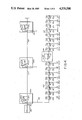
- FIG. 3 is a schematic diagram of a directional coupler employed in a typical cable system for use in explaining the use of the subscriber terminal of the invention in the cable systems illustrated in FIGS. 4 and 5;
- FIG. 4 is a schematic design of a cable system in which a fault is located in subscriber drop line.
- FIG. 5 is a schematic diagram similar to that of FIG. 4 of a cable system in which a fault is located in a feeder line cable span.
- a subscriber terminal in accordance with the invention is connected through a cable 12 to a cable television system headend or central station (not shown in the drawing).
- the subscriber terminal 10 includes a control signal receiver 14, which receives a coded frequency shift-keyed command signal from the headend via the cable 12.
- the control receiver 14 detects the frequency shift-keyed signal and applies a corresponding signal containing, in digital form, information obtained from the headend specifying the address of the subscriber terminal, the frequency or frequencies at which ingress is to be monitored, and the system return transmit signal frequency to a microcomputer or microprocessor 16.
- the ingress-monitoring frequencies may be established as a result of actual ingress detected at the headend or as a function of the time of year during which different types of ingress are anticipated.
- the subscriber terminal 10 also includes a signal level measurement receiver, generally designated 18, which detects ingress on the cable 12 and applies an ingress signal to the microprocessor 16, and a return frequency transmitter 20 connected to the microprocessor 16 and to the cable 12 to transmit information concerning the detected ingress to the headend via the cable.
- the signal level measurement receiver 18 includes a return spectrum receiver 22 having an input coupled to the cable 12, an analog-to-digital converter coupled to the output of receiver 22 and to an input of microcomputer 16, a digital-to-analog converter 26 connected to an output of the microprocessor 16, and a voltage-controlled oscillator 28 connected to the output of converter 26 and to the mixer stage of receiver 22.
- the output frequency of oscillator 28 is established by a control voltage received from the output of digital-to-analog converter 26, the input of which receives a digital frequency control signal from microprocessor 16.
- Microprocessor 16 contains a program, a portion of which is illustrated in FIG. 2, which may be stored in the microprocessor in, for example, a programmable read-only memory (PROM).
- the monitored ingress frequencies are preferably selected to fall within one of the available return frequencies at which information from the subscriber's security terminal or the like is transmitted back to the headend along the cable 12.
- the microprocessor 16 may be preprogrammed to generate a frequency-scan signal to establish output frequencies for oscillator 28 to cause the return spectrum receiver 22 to monitor ingress at a number of predetermined frequencies of, for example, 5, 10, 20 and 30 mHz.
- the digital frequency-scan signal from the microprocessor 16 is applied to the input of digital-to-analog converter 26, which converts that signal to a corresponding series of analog voltages at different levels that are applied sequentially to the control terminal of variable-frequency oscillator 28.
- the number of voltage levels developed at the output of converter 26 is the same as the number of monitored ingress frequencies, here four.
- Oscillator 28, in accordance with these four scan voltages, sequentially provides a series of local oscillator signals at four different frequencies to the mixer stage of receiver 22 in which these signals are mixed or heterodyned with radio-frequency signals that may have gained ingress onto the cable.
- the signal produced by oscillator 28 thus heterodynes with any ingress signals that may be on the cable at the several preselected monitored ingress frequencies so as to develop a series of ingress-detect signals at a predetermined intermediate frequency.
- the resulting intermediate-frequency signal developed in receiver 22 will be of a magnitude that corresponds to the magnitude of the detected ingress signal.
- These intermediate-frequency signals are detected in receiver 22 to produce a series of analog signals each having an amplitude that is proportional to the magnitude of any radio-frequency ingress that is detected at the four monitored frequencies.
- These analog output signals from receiver 22 are applied sequentially to the input of analog-to-digital converter 24, which converts the signals to a corresponding series of digital signals that are applied to the microprocessor 16 in which the signals are processed to produce information relative to the magnitudes of each of the detected ingress signals at the monitored ingress frequencies.
- the return frequency transmitter 20 includes a return spectrum transmitter 30 having an input coupled to an output of microprocessor 16; a digital-to-analog converter 22, which includes an input coupled to an output of microprocessor 16; a voltage-controlled oscillator 34 having an input coupled to the output of converter 32, and an output applied to the mixer stage of transmitter 30; and a variable attenuator 36 connected intermediate the output of the return spectrum transmitter 30 and the cable 12.
- the ingress-detect signals detected in receiver 22 and applied in digital form to the microprocessor 16 are processed there in accordance with the latter's prestored program. That operation produces a digital transmit-control signal, which is applied to an input of return spectrum transmitter 30.
- the transmit-control signal thus represents the magnitude and frequency of any detected ingress, as well as the address of the subscriber terminal.
- the microprocessor 16 also applies a frequency-control digital signal to the input of digital-to-analog converter 32 based on the transmit frequency command signal received at receiver 14 from the headend.
- the frequency-control signal is converted in converter 32 to a corresponding analog voltage that is, in turn, applied to the control terminal of voltage-controlled oscillator 34 to control the latter's frequency of oscillation.
- the radio-frequency output of oscillator 34 is applied to the mixer stage of return spectrum transmitter 30, where the signal is modulated by the transmit-control digital signal applied to the return spectrum transmitter 30 from the microprocessor 16.
- the output of return spectrum transmitter 30 is thus a frequency shift-keyed radio-frequency signal having a center transmit frequency established by the coded frequency command signal received from the central station, and which is modulated by the digital ingress-detect signal developed by the microprocessor 16. That signal, as noted, contains information relative to the magnitude and frequency of the ingress signals detected at receiver 22, as well as the address of the particular subscriber terminal.
- variable attenuator 36 which also receives a control signal from the microprocessor 16 that represents the magnitude of the detected ingress signal at the transmit frequency.
- the amount of attenuation provided by attenuator 36 to the transmit signal is decreased to permit a greater level of the transmit signal to be transmitted on the cable to the headend at that frequency.
- the attenuation provided in attenuator 36 to the return transmit signal is relatively high so that the return signal on the cable does not exceed certain maximum transmission levels.
- the attenuator 36 may also be operated in response to a transmission-terminate signal from the microprocessor 16 to effectively turn off the return transmitter during those periods in which the subscriber terminal is not addressed from the headend.
- microprocessor 16 is programmed according to known techniques to carry out the following functions:
- step 38 the program is entered in step 38 wherein the assigned control frequency and subscriber address, as established by the frequency shift-keyed signal received at forward spectrum receiver 14, are monitored.
- the received address is entered in step 40 where a determination is made if the received address signal is that of the particular subscriber terminal. If the received address does not match the address of the subscriber terminal, the program returns to step 38; if the address matches that of the subscriber, the program proceeds to step 42 in which the return spectrum receiver 22 is instructed to measure the radio-frequency signal on the cable at the specified ingress frequencies as determined by the signal from the headend which establishes the frequency to be monitored for ingress in the return spectrum.
- step 44 the return spectrum transmitter 30 is instructed by means of a signal applied to digital-to-analog converter 32 to operate at a return frequency as also specified in the coded signal received at receiver 14.
- step 46 of the program the return transmitter signal at the specified return frequency is modulated by a signal representative of the monitored radio-frequency ingress signals. The program is then returned to step 38.
- each of the terminals on the system receives a start command signal from the central headend station, each terminal being separately and sequentially addressed.
- the central station upon receiving signals from one or more of the terminals indicating the detection of an excessive level of ingress at one or more of the monitored frequencies in the manner described above, will select a transmit frequency that is different from any of the frequencies at which a greater than specified magnitude of ingress has been detected for use in subsequent return transmissions so as to avoid interference in subsequent return transmissions as a result of the ingress.
- the detection and measurement of the monitored ingress signals at the various subscriber terminals in the manner described above can also be used to accurately and quickly locate the fault in the cable at which the ambient radio-frequency signal in the return spectrum is gaining ingress into the cable, as in the examples given with reference to FIGS. 4 and 5, which illustrate a cable system in which a fault has occurred along one cable span of a cable system and in which the resulting ingress is detected and measured in a plurality of subscriber terminals connected to that cable span by means of the subscriber terminal of the invention as illustrated in FIG. 1.
- the cable system includes a headend 48 connected by a length of coaxial cable 50 to one of a series of trunk stations 52, a, b . . . n, spaced along the trunk cable 50.
- Each of the trunk stations 52 includes a pair of oppositely connected forward and return amplifiers 54 and 56 with a filter 58 connected therebetween.
- the forward amplifier 54 passes signals in the forward spectrum of 50-400 mHz
- the return amplifier 56 passes the return signals in the return frequency spectrum of 5-30 mHz.
- Each of the filters 58 is connected by means of a feeder line 60 to a cable span 62 in which a line extender 64 comprising a forward amplifier 66 and a return amplifier 68 is interposed at suitable locations.
- Cable span 62 is respectively connected by means of directional couplers 70a-p to a series of drop lines 72-p, the latter being respectively connected to a corresponding number of subscriber terminals (not shown in FIGS. 4 and 5).
- Each of directional couplers 70 is illustrated in FIGS. 4 and 5 in accordance with the representation of a coupler provided in FIG. 3 which, as shown in the accompanying chart, has an attenuation expressed in db between the "in” terminal and tap by the numerical indication in FIGS. 4 and 5 corresponding to the letter a in FIG. 3, and an attenuation expressed in db between the "out" terminal and the tap by the numerical indication corresponding to the letter b.
- each of the lengths of cable spans between adjacent couplers 70 has an attenuation of 3 db in the forward direction and an attenuation of 1 db in the reverse or return direction. It is also assumed that the level of ingress at a location on the cable at which a fault occurs is 0 dbmv.
- the ingress at the subscriber terminal connected to that drop line will thus be at a level of odbmv and the levels of ingress measured at the subscriber terminals connected to that cable span that result from the fault will be at the values shown in FIG. 4 at the drop lines 72a-l and 72n-p.
- the levels of ingress measured at the various subscriber terminals connected along cable span 62 will be at the values indicated in FIG. 5 at each of the drop lines 72a-p, as a result of the attenuation to the ingress offered by the directional couplers and lengths of cable span between the location of the fault and the subscriber terminals at which the levels of the ingress are measured.
- the subscriber terminals sequentially transmit signals at the specified return frequency to the headend indicating the level of ingress detected at each terminal in the manner described above.
- a data-processing system at the headend can provide the system operator with an ingress magnitude map of the entire cable system. This information could then be used by the cable system maintenance personnel to isolate the location of the cable fault at which the ingress is occurring to enable them more expeditiously to determine the exact location along the system at which the cable shielding is faulty.
- the subscriber terminal of the present invention is capable of quickly and accurately locating sources of radio-frequency ingress into a cable television system, thereby to expedite the correction of the ingress problem and to cause subsequent return transmissions to be unaffected by the ingress so long as the ingress remains uncorrected. It will also be appreciated that although the present invention has been described hereinabove with respect to one embodiment, modifications may be made therein, such as in the number and frequencies of the monitored ingress signals, without necessarily departing from the spirit and scope of the invention.
Abstract
Description
Claims (8)
Priority Applications (1)
| Application Number | Priority Date | Filing Date | Title |
|---|---|---|---|
| US06/624,804 US4520508A (en) | 1982-12-21 | 1984-06-26 | Subscriber terminal for monitoring radio-frequency signal ingress into cable television systems |
Applications Claiming Priority (2)
| Application Number | Priority Date | Filing Date | Title |
|---|---|---|---|
| US45185882A | 1982-12-21 | 1982-12-21 | |
| US06/624,804 US4520508A (en) | 1982-12-21 | 1984-06-26 | Subscriber terminal for monitoring radio-frequency signal ingress into cable television systems |
Related Parent Applications (1)
| Application Number | Title | Priority Date | Filing Date |
|---|---|---|---|
| US45185882A Continuation-In-Part | 1982-12-21 | 1982-12-21 |
Publications (1)
| Publication Number | Publication Date |
|---|---|
| US4520508A true US4520508A (en) | 1985-05-28 |
Family
ID=27036545
Family Applications (1)
| Application Number | Title | Priority Date | Filing Date |
|---|---|---|---|
| US06/624,804 Expired - Lifetime US4520508A (en) | 1982-12-21 | 1984-06-26 | Subscriber terminal for monitoring radio-frequency signal ingress into cable television systems |
Country Status (1)
| Country | Link |
|---|---|
| US (1) | US4520508A (en) |
Cited By (86)
| Publication number | Priority date | Publication date | Assignee | Title |
|---|---|---|---|---|
| US4586078A (en) * | 1983-09-12 | 1986-04-29 | Zenith Electronics Corporation | CATV upstream signal transmission at nonharmonic video frequencies |
| US4633309A (en) * | 1985-05-06 | 1986-12-30 | Oak Industries Inc. | Cable television master/slave decoder control |
| US4670889A (en) * | 1983-09-07 | 1987-06-02 | British Telecommunications Plc | Frequency control for point to multipoint radio |
| US4673976A (en) * | 1984-05-31 | 1987-06-16 | American Television & Communications Corporation | Cable television system data verification apparatus |
| US4684980A (en) * | 1984-05-31 | 1987-08-04 | American Television & Communications Corporation | System for controlling communications on a cable television network |
| US4710956A (en) * | 1984-05-31 | 1987-12-01 | American Television & Communications Corporation | Cable television system |
| US4755871A (en) * | 1986-11-25 | 1988-07-05 | Magus, Ltd. | Control of rf answer pulses in a TV answer back system |
| US4980924A (en) * | 1986-11-19 | 1990-12-25 | Plessey Overseas Limited | HF radio communication systems with frequency management |
| US5142690A (en) * | 1990-03-20 | 1992-08-25 | Scientific-Atlanta, Inc. | Cable television radio frequency data processor |
| US5155590A (en) * | 1990-03-20 | 1992-10-13 | Scientific-Atlanta, Inc. | System for data channel level control |
| FR2680935A1 (en) * | 1991-08-30 | 1993-03-05 | Telediffusion Fse | Installation with a wired network for distributing audiovisual programmes and for digital communication with a digital data bridge |
| US5225902A (en) * | 1990-03-20 | 1993-07-06 | Scientific-Atlanta, Inc. | Automatic frequency selection in a bi-directional cable television system |
| US5235619A (en) * | 1990-03-20 | 1993-08-10 | Scientific-Atlanta, Inc. | Cable television radio frequency subscriber data transmission apparatus and rf return method |
| US5361394A (en) * | 1989-12-19 | 1994-11-01 | Kabushiki Kaisha Toshiba | Upstream signal control apparatus for cable television system |
| WO1998007276A1 (en) * | 1996-08-15 | 1998-02-19 | Com21, Inc. | Tv and data cable system ingress noise blocker |
| US5787335A (en) * | 1996-11-18 | 1998-07-28 | Ethnic-American Broadcasting Co, Lp | Direct broadcast satellite system for multiple dwelling units |
| US5790806A (en) * | 1996-04-03 | 1998-08-04 | Scientific-Atlanta, Inc. | Cable data network architecture |
| US5819159A (en) * | 1996-07-25 | 1998-10-06 | At&T Corp | Method for asymmetrically attenuating signals in a transmission system |
| US5845191A (en) * | 1996-07-25 | 1998-12-01 | At&T Corp | Method for asymmetrically attenuating signals in a transmission system |
| EP0916223A1 (en) * | 1996-07-31 | 1999-05-19 | Trilithic, Inc. | Return path ingress noise measurement system |
| US5937330A (en) * | 1997-02-18 | 1999-08-10 | General Instrument Corporation | Settop terminal controlled return path filter for minimizing noise ingress on bidirectional cable systems |
| US5939887A (en) * | 1997-09-05 | 1999-08-17 | Tektronix, Inc. | Method for measuring spectral energy interference in a cable transmission system |
| US5956074A (en) * | 1997-03-11 | 1999-09-21 | Sclafani; Peter J. | Cable television return display unit |
| WO2000013424A1 (en) * | 1998-09-02 | 2000-03-09 | Wavetek Wandel Goltermann, Inc. | Catv return path impairment detection and location system |
| US6215514B1 (en) | 1997-06-27 | 2001-04-10 | Trilithic, Inc. | Ingress monitoring system |
| WO2001062003A1 (en) | 2000-02-16 | 2001-08-23 | Kjell Arne Ljungdahl | Cable tv system or other similar communication system |
| US6337711B1 (en) | 1999-06-22 | 2002-01-08 | Comsonics, Inc. | Transmission performance testing |
| US6393063B1 (en) * | 1996-01-03 | 2002-05-21 | John F. Flood | Two-way digital communication system and method without carrier lock-on or ingress interference |
| US6425132B1 (en) | 1998-04-06 | 2002-07-23 | Wavetek Corporation | Ingress testing of CATV system utilizing remote selection of CATV node |
| US20020141347A1 (en) * | 2001-03-30 | 2002-10-03 | Harp Jeffrey C. | System and method of reducing ingress noise |
| US20030022645A1 (en) * | 2001-07-26 | 2003-01-30 | Runzo Joseph Donald | System and method for signal validation and leakage detection |
| US20030033609A1 (en) * | 2000-05-16 | 2003-02-13 | Zimmerman Dennis A | Device and method of determining location of signal ingress |
| US6530088B1 (en) | 1996-06-03 | 2003-03-04 | Scientific-Atlanta, Inc. | Apparatus for automatic sensing of line amplifier configuration for status monitoring |
| US20030179723A1 (en) * | 2002-03-21 | 2003-09-25 | Abram Novak | Satellite signal distribution systems |
| DE10218668C1 (en) * | 2002-04-19 | 2003-10-09 | Satelliten Und Kabelfernsehanl | System for analyzing noise signals in community antenna TV system return channel has spectrum converter with IF amplifier input connected to return channel input via filters and mixers |
| US6804826B1 (en) | 1999-07-28 | 2004-10-12 | Trilithic, Inc. | Radio frequency leakage detection system for CATV system |
| US6915530B1 (en) * | 1994-11-30 | 2005-07-05 | General Instrument Corporation | Ingress detection and characterization by time/frequency map |
| US7254827B1 (en) | 2000-05-08 | 2007-08-07 | Sunrise Telecom Incorporated | Ingress monitoring system and method |
| US20080133308A1 (en) * | 2006-11-27 | 2008-06-05 | Harris James E | Leakage location methods |
| US20090265745A1 (en) * | 2008-04-17 | 2009-10-22 | Egan Jr John M | Reversible Faceplate Terminal Adapter Which Changes Signal Flow Direction |
| US20090300534A1 (en) * | 2008-05-30 | 2009-12-03 | Trilithic, Inc. | Apparatus and method for displaying network status |
| US20100017842A1 (en) * | 2008-07-17 | 2010-01-21 | Wells Chad T | Passive-Active Terminal Adapter and Method Having Automatic Return Loss Control |
| US20100064078A1 (en) * | 2008-08-15 | 2010-03-11 | Powell Thomas J | Wireless communication between testing instrument and network |
| US20100095344A1 (en) * | 2008-10-13 | 2010-04-15 | Newby Charles F | Ingress Noise Inhibiting Network Interface Device and Method for Cable Television Networks |
| US20100100921A1 (en) * | 2008-10-16 | 2010-04-22 | John Mezzalingua Associates, Inc. | Dynamically configurable frequency band selection device between catv distribution system and catv user |
| US20100100922A1 (en) * | 2008-10-16 | 2010-04-22 | John Mezzalingua Associates, Inc. | Downstream output level and/or output level tilt compensation device between catv distribution system and catv user |
| US20100100918A1 (en) * | 2008-10-21 | 2010-04-22 | Egan Jr John M | Multi-Port Entry Adapter, Hub and Method for Interfacing a CATV Network and a MoCA Network |
| US20100125877A1 (en) * | 2008-10-21 | 2010-05-20 | Wells Chad T | CATV Entry Adapter and Method for Preventing Interference with eMTA Equipment from MoCA Signals |
| US20100146564A1 (en) * | 2008-10-21 | 2010-06-10 | Halik Gregory F | CATV Entry Adapter and Method Utilizing Directional Couplers for MoCA Signal Communication |
| US7752649B1 (en) * | 1981-11-03 | 2010-07-06 | Personalized Media Communications, Llc | Signal processing apparatus and methods |
| US7784082B1 (en) * | 1981-11-03 | 2010-08-24 | Personalized Media Communications, Llc | Signal processing apparatus and methods |
| US20100251322A1 (en) * | 2009-03-30 | 2010-09-30 | Raymond Palinkas | Upstream bandwidth conditioning device |
| US20100251320A1 (en) * | 2009-03-30 | 2010-09-30 | Shafer Steven K | Automatic return path switching for a signal conditioning device |
| US20100251321A1 (en) * | 2009-03-30 | 2010-09-30 | Raymond Palinkas | Upstream bandwidth conditioning device |
| US20100251323A1 (en) * | 2009-03-30 | 2010-09-30 | Jackson David H | Upstream bandwidth conditioning device |
| US20100244980A1 (en) * | 2009-03-30 | 2010-09-30 | Olson Thomas A | Method and apparatus for a self-terminating signal path |
| US20100251314A1 (en) * | 2009-03-30 | 2010-09-30 | John Mezzalingua Associates, Inc. | Total bandwidth conditioning device |
| US20100301972A1 (en) * | 2009-05-29 | 2010-12-02 | John Mezzalingua Associates, Inc. | Self-terminating coaxial cable port |
| US20110072472A1 (en) * | 2009-09-21 | 2011-03-24 | Wells Chad T | Passive Multi-Port Entry Adapter and Method for Preserving Downstream CATV Signal Strength within In-Home Network |
| US20110085480A1 (en) * | 2009-10-09 | 2011-04-14 | John Mezzalingua Associates, Inc. | Upstream bandwidth conditioning device |
| US20110085452A1 (en) * | 2009-10-09 | 2011-04-14 | John Mezzalingua Associates, Inc. | Upstream bandwidth level measurement device |
| US20110085045A1 (en) * | 2009-10-09 | 2011-04-14 | John Mezzalingua Associates, Inc. | Modulation analyzer and level measurement device |
| US20110085586A1 (en) * | 2009-10-09 | 2011-04-14 | John Mezzalingua Associates, Inc. | Total bandwidth conditioning device |
| US20110088077A1 (en) * | 2009-10-09 | 2011-04-14 | John Mezzalingua Associates, Inc. | Downstream bandwidth conditioning device |
| US20110181371A1 (en) * | 2010-01-26 | 2011-07-28 | John Mezzalingua Associates, Inc. | Band selective isolation bridge for splitter |
| US20110187481A1 (en) * | 2010-02-01 | 2011-08-04 | John Mezzalingua Associates, Inc. | Multipath mitigation circuit for home network |
| US8141122B2 (en) | 2009-03-30 | 2012-03-20 | John Mezzalingua Associates, Inc. | RF terminate/permit system |
| US8464301B2 (en) | 2008-10-16 | 2013-06-11 | Ppc Broadband, Inc. | Upstream bandwidth conditioning device between CATV distribution system and CATV user |
| US8479247B2 (en) | 2010-04-14 | 2013-07-02 | Ppc Broadband, Inc. | Upstream bandwidth conditioning device |
| US8532488B2 (en) | 2011-07-01 | 2013-09-10 | Certusview Technologies, Llc | Cable communication systems and methods employing QAM upstream channels below 16.4 MHz for increased aggregate deployed upstream capacity to support voice and/or data services |
| US20130258910A1 (en) * | 2012-03-29 | 2013-10-03 | Fujitsu Limited | Wireless communication device |
| US8561125B2 (en) | 2010-08-30 | 2013-10-15 | Ppc Broadband, Inc. | Home network frequency conditioning device and method |
| US8724681B2 (en) | 2011-06-27 | 2014-05-13 | Jds Uniphase Corporation | Ingress noise localization in a cable network |
| US8752108B2 (en) | 2010-07-21 | 2014-06-10 | Magella Bouchard | System and method for detecting signal ingress interferences |
| US8949918B2 (en) | 2013-03-15 | 2015-02-03 | Certusview Technologies, Llc | Hybrid fiber-coaxial (HFC) cable communication systems having well-aligned optical and radio-frequency links to facilitate upstream channel plans having high aggregate data capacity |
| US9264012B2 (en) | 2012-06-25 | 2016-02-16 | Ppc Broadband, Inc. | Radio frequency signal splitter |
| US20160112734A1 (en) * | 2014-09-24 | 2016-04-21 | Cable Television Laboratories, Inc. | Isolating an upstream noise source in a cable television network |
| US9351051B2 (en) | 2008-10-13 | 2016-05-24 | Ppc Broadband, Inc. | CATV entry adapter and method for distributing CATV and in-home entertainment signals |
| US9357163B2 (en) | 2012-09-20 | 2016-05-31 | Viavi Solutions Inc. | Characterizing ingress noise |
| US10021343B2 (en) | 2010-12-21 | 2018-07-10 | Ppc Broadband, Inc. | Method and apparatus for reducing isolation in a home network |
| US10142677B2 (en) | 2008-10-21 | 2018-11-27 | Ppc Broadband, Inc. | Entry device for a CATV network |
| US10212392B2 (en) | 2016-06-30 | 2019-02-19 | Ppc Broadband, Inc. | Passive enhanced MoCA entry device |
| US10250781B1 (en) | 2017-11-16 | 2019-04-02 | Via Vi Solutions, Inc. | Instrument for locating a noise source in a CATV system and method of using same |
| US10764532B2 (en) | 2012-10-30 | 2020-09-01 | Viavi Solutions Inc. | Method and system for locating ingress utilizing customer premises equipment |
| US11076191B2 (en) | 2018-01-19 | 2021-07-27 | Ppc Broadband, Inc. | Systems and methods for extending an in-home splitter network |
| US11910052B2 (en) | 2008-10-21 | 2024-02-20 | Ppc Broadband, Inc. | Entry device for communicating external network signals and in-home network signals |
Citations (5)
| Publication number | Priority date | Publication date | Assignee | Title |
|---|---|---|---|---|
| US3668307A (en) * | 1970-03-30 | 1972-06-06 | Kms Ind Inc | Two-way community antenna television system |
| US3806814A (en) * | 1972-04-26 | 1974-04-23 | Hughes Aircraft Co | Phantom subscriber |
| US4317215A (en) * | 1978-09-13 | 1982-02-23 | Pioneer Electronic Corporation | Tuning system for CATV terminal |
| US4322854A (en) * | 1979-05-18 | 1982-03-30 | Allan B. Bundens | Data communications terminal |
| US4408345A (en) * | 1979-06-21 | 1983-10-04 | Pioneer Electronic Corporation | Remote line monitoring method and device for CATV system |
-
1984
- 1984-06-26 US US06/624,804 patent/US4520508A/en not_active Expired - Lifetime
Patent Citations (5)
| Publication number | Priority date | Publication date | Assignee | Title |
|---|---|---|---|---|
| US3668307A (en) * | 1970-03-30 | 1972-06-06 | Kms Ind Inc | Two-way community antenna television system |
| US3806814A (en) * | 1972-04-26 | 1974-04-23 | Hughes Aircraft Co | Phantom subscriber |
| US4317215A (en) * | 1978-09-13 | 1982-02-23 | Pioneer Electronic Corporation | Tuning system for CATV terminal |
| US4322854A (en) * | 1979-05-18 | 1982-03-30 | Allan B. Bundens | Data communications terminal |
| US4408345A (en) * | 1979-06-21 | 1983-10-04 | Pioneer Electronic Corporation | Remote line monitoring method and device for CATV system |
Cited By (168)
| Publication number | Priority date | Publication date | Assignee | Title |
|---|---|---|---|---|
| US7752649B1 (en) * | 1981-11-03 | 2010-07-06 | Personalized Media Communications, Llc | Signal processing apparatus and methods |
| US7784082B1 (en) * | 1981-11-03 | 2010-08-24 | Personalized Media Communications, Llc | Signal processing apparatus and methods |
| US4670889A (en) * | 1983-09-07 | 1987-06-02 | British Telecommunications Plc | Frequency control for point to multipoint radio |
| US4586078A (en) * | 1983-09-12 | 1986-04-29 | Zenith Electronics Corporation | CATV upstream signal transmission at nonharmonic video frequencies |
| US4673976A (en) * | 1984-05-31 | 1987-06-16 | American Television & Communications Corporation | Cable television system data verification apparatus |
| US4684980A (en) * | 1984-05-31 | 1987-08-04 | American Television & Communications Corporation | System for controlling communications on a cable television network |
| US4710956A (en) * | 1984-05-31 | 1987-12-01 | American Television & Communications Corporation | Cable television system |
| US4633309A (en) * | 1985-05-06 | 1986-12-30 | Oak Industries Inc. | Cable television master/slave decoder control |
| US4980924A (en) * | 1986-11-19 | 1990-12-25 | Plessey Overseas Limited | HF radio communication systems with frequency management |
| US4755871A (en) * | 1986-11-25 | 1988-07-05 | Magus, Ltd. | Control of rf answer pulses in a TV answer back system |
| US5361394A (en) * | 1989-12-19 | 1994-11-01 | Kabushiki Kaisha Toshiba | Upstream signal control apparatus for cable television system |
| US5142690A (en) * | 1990-03-20 | 1992-08-25 | Scientific-Atlanta, Inc. | Cable television radio frequency data processor |
| US5235619A (en) * | 1990-03-20 | 1993-08-10 | Scientific-Atlanta, Inc. | Cable television radio frequency subscriber data transmission apparatus and rf return method |
| US5225902A (en) * | 1990-03-20 | 1993-07-06 | Scientific-Atlanta, Inc. | Automatic frequency selection in a bi-directional cable television system |
| US5155590A (en) * | 1990-03-20 | 1992-10-13 | Scientific-Atlanta, Inc. | System for data channel level control |
| FR2680935A1 (en) * | 1991-08-30 | 1993-03-05 | Telediffusion Fse | Installation with a wired network for distributing audiovisual programmes and for digital communication with a digital data bridge |
| US6915530B1 (en) * | 1994-11-30 | 2005-07-05 | General Instrument Corporation | Ingress detection and characterization by time/frequency map |
| US6393063B1 (en) * | 1996-01-03 | 2002-05-21 | John F. Flood | Two-way digital communication system and method without carrier lock-on or ingress interference |
| US5790806A (en) * | 1996-04-03 | 1998-08-04 | Scientific-Atlanta, Inc. | Cable data network architecture |
| US6530088B1 (en) | 1996-06-03 | 2003-03-04 | Scientific-Atlanta, Inc. | Apparatus for automatic sensing of line amplifier configuration for status monitoring |
| US5845191A (en) * | 1996-07-25 | 1998-12-01 | At&T Corp | Method for asymmetrically attenuating signals in a transmission system |
| US5819159A (en) * | 1996-07-25 | 1998-10-06 | At&T Corp | Method for asymmetrically attenuating signals in a transmission system |
| EP0916223A1 (en) * | 1996-07-31 | 1999-05-19 | Trilithic, Inc. | Return path ingress noise measurement system |
| US6292944B1 (en) | 1996-07-31 | 2001-09-18 | Trilithic, Inc. | Return path ingress in a two-way CATV system |
| EP0916223A4 (en) * | 1996-07-31 | 2000-01-12 | Trilithic Inc | Return path ingress noise measurement system |
| US6049693A (en) * | 1996-08-15 | 2000-04-11 | Com21, Inc. | Upstream ingress noise blocking filter for cable television system |
| US6094211A (en) * | 1996-08-15 | 2000-07-25 | Com21, Inc. | TV and data cable system ingress noise blocker |
| WO1998007276A1 (en) * | 1996-08-15 | 1998-02-19 | Com21, Inc. | Tv and data cable system ingress noise blocker |
| US5787335A (en) * | 1996-11-18 | 1998-07-28 | Ethnic-American Broadcasting Co, Lp | Direct broadcast satellite system for multiple dwelling units |
| US5937330A (en) * | 1997-02-18 | 1999-08-10 | General Instrument Corporation | Settop terminal controlled return path filter for minimizing noise ingress on bidirectional cable systems |
| US5956074A (en) * | 1997-03-11 | 1999-09-21 | Sclafani; Peter J. | Cable television return display unit |
| US6215514B1 (en) | 1997-06-27 | 2001-04-10 | Trilithic, Inc. | Ingress monitoring system |
| US5939887A (en) * | 1997-09-05 | 1999-08-17 | Tektronix, Inc. | Method for measuring spectral energy interference in a cable transmission system |
| US6425132B1 (en) | 1998-04-06 | 2002-07-23 | Wavetek Corporation | Ingress testing of CATV system utilizing remote selection of CATV node |
| WO2000013424A1 (en) * | 1998-09-02 | 2000-03-09 | Wavetek Wandel Goltermann, Inc. | Catv return path impairment detection and location system |
| US6337711B1 (en) | 1999-06-22 | 2002-01-08 | Comsonics, Inc. | Transmission performance testing |
| US20050034170A1 (en) * | 1999-07-28 | 2005-02-10 | Bush Terry W. | Radio frequency leakage detection system for CATV system |
| US6804826B1 (en) | 1999-07-28 | 2004-10-12 | Trilithic, Inc. | Radio frequency leakage detection system for CATV system |
| US20030014765A1 (en) * | 2000-02-16 | 2003-01-16 | Ljungdahl Kjell Arne | Cable tv system or other similar communication system |
| EP1264483A1 (en) * | 2000-02-16 | 2002-12-11 | Kjell Arne Ljungdahl | Cable tv system or other similar communication system |
| WO2001062003A1 (en) | 2000-02-16 | 2001-08-23 | Kjell Arne Ljungdahl | Cable tv system or other similar communication system |
| US7283479B2 (en) * | 2000-02-16 | 2007-10-16 | Spacenet Proxilliant Systems Ab | Cable TV system or other similar communication system |
| US7254827B1 (en) | 2000-05-08 | 2007-08-07 | Sunrise Telecom Incorporated | Ingress monitoring system and method |
| EP1295463A4 (en) * | 2000-05-16 | 2005-12-14 | Comsonics Inc | Device and method of determining location of signal ingress |
| US20030033609A1 (en) * | 2000-05-16 | 2003-02-13 | Zimmerman Dennis A | Device and method of determining location of signal ingress |
| US6978476B2 (en) * | 2000-05-16 | 2005-12-20 | Comsonics | Device and method of determining location of signal ingress |
| EP1295463A2 (en) * | 2000-05-16 | 2003-03-26 | Comsonics, Inc. | Device and method of determining location of signal ingress |
| US20020141347A1 (en) * | 2001-03-30 | 2002-10-03 | Harp Jeffrey C. | System and method of reducing ingress noise |
| US7395548B2 (en) * | 2001-07-26 | 2008-07-01 | Comsonics, Inc. | System and method for signal validation and leakage detection |
| US20030022645A1 (en) * | 2001-07-26 | 2003-01-30 | Runzo Joseph Donald | System and method for signal validation and leakage detection |
| US20030179723A1 (en) * | 2002-03-21 | 2003-09-25 | Abram Novak | Satellite signal distribution systems |
| US7352991B2 (en) | 2002-03-21 | 2008-04-01 | National Antenna Systems | Satellite signal distribution systems |
| DE10218668C1 (en) * | 2002-04-19 | 2003-10-09 | Satelliten Und Kabelfernsehanl | System for analyzing noise signals in community antenna TV system return channel has spectrum converter with IF amplifier input connected to return channel input via filters and mixers |
| US20080133308A1 (en) * | 2006-11-27 | 2008-06-05 | Harris James E | Leakage location methods |
| US20090265745A1 (en) * | 2008-04-17 | 2009-10-22 | Egan Jr John M | Reversible Faceplate Terminal Adapter Which Changes Signal Flow Direction |
| US20090300534A1 (en) * | 2008-05-30 | 2009-12-03 | Trilithic, Inc. | Apparatus and method for displaying network status |
| US20100017842A1 (en) * | 2008-07-17 | 2010-01-21 | Wells Chad T | Passive-Active Terminal Adapter and Method Having Automatic Return Loss Control |
| US10257462B2 (en) | 2008-07-17 | 2019-04-09 | Ppc Broadband, Inc. | Adapter for a cable-television network |
| US9769418B2 (en) | 2008-07-17 | 2017-09-19 | Ppc Broadband, Inc. | Passive-active terminal adapter and method having automatic return loss control |
| US9363469B2 (en) | 2008-07-17 | 2016-06-07 | Ppc Broadband, Inc. | Passive-active terminal adapter and method having automatic return loss control |
| US20100064078A1 (en) * | 2008-08-15 | 2010-03-11 | Powell Thomas J | Wireless communication between testing instrument and network |
| US9781472B2 (en) | 2008-10-13 | 2017-10-03 | Ppc Broadband, Inc. | CATV entry adapter and method for distributing CATV and in-home entertainment signals |
| US10154302B2 (en) | 2008-10-13 | 2018-12-11 | Ppc Broadband, Inc. | CATV entry adapter and method for distributing CATV and in-home entertainment signals |
| US10187673B2 (en) | 2008-10-13 | 2019-01-22 | Ppc Broadband, Inc. | Ingress noise inhibiting network interface device and method for cable television networks |
| US20100095344A1 (en) * | 2008-10-13 | 2010-04-15 | Newby Charles F | Ingress Noise Inhibiting Network Interface Device and Method for Cable Television Networks |
| US9647851B2 (en) | 2008-10-13 | 2017-05-09 | Ppc Broadband, Inc. | Ingress noise inhibiting network interface device and method for cable television networks |
| US10045056B2 (en) | 2008-10-13 | 2018-08-07 | Ppc Broadband, Inc. | Ingress noise inhibiting network interface device and method for cable television networks |
| US9351051B2 (en) | 2008-10-13 | 2016-05-24 | Ppc Broadband, Inc. | CATV entry adapter and method for distributing CATV and in-home entertainment signals |
| US20100100922A1 (en) * | 2008-10-16 | 2010-04-22 | John Mezzalingua Associates, Inc. | Downstream output level and/or output level tilt compensation device between catv distribution system and catv user |
| US8832767B2 (en) | 2008-10-16 | 2014-09-09 | Ppc Broadband, Inc. | Dynamically configurable frequency band selection device between CATV distribution system and CATV user |
| US20100100921A1 (en) * | 2008-10-16 | 2010-04-22 | John Mezzalingua Associates, Inc. | Dynamically configurable frequency band selection device between catv distribution system and catv user |
| US10924811B2 (en) | 2008-10-16 | 2021-02-16 | Ppc Broadband, Inc. | Compensation device for maintaining a desired signal quality in transmitted signals |
| US8001579B2 (en) | 2008-10-16 | 2011-08-16 | John Mezzalingua Associates, Inc. | Downstream output level and/or output level tilt compensation device between CATV distribution system and CATV user |
| US10264325B2 (en) | 2008-10-16 | 2019-04-16 | Ppc Broadband, Inc. | System, method and device having teaching and commerce subsystems |
| US8464301B2 (en) | 2008-10-16 | 2013-06-11 | Ppc Broadband, Inc. | Upstream bandwidth conditioning device between CATV distribution system and CATV user |
| US9271026B2 (en) | 2008-10-16 | 2016-02-23 | Ppc Broadband, Inc. | Dynamically configurable frequency band selection device between CATV distribution system and CATV user |
| US10419813B2 (en) | 2008-10-21 | 2019-09-17 | Ppc Broadband, Inc. | Passive multi-port entry adapter for preserving downstream CATV signal strength |
| US10154304B2 (en) | 2008-10-21 | 2018-12-11 | Ppc Broadband, Inc. | Methods for controlling CATV signal communication between a CATV network and an in-home network, and preserving downstream CATV signal strength within the in-home network |
| US10154303B2 (en) | 2008-10-21 | 2018-12-11 | Ppc Broadband, Inc. | Entry adapter that blocks different frequency bands and preserves downstream signal strength |
| US10284904B2 (en) | 2008-10-21 | 2019-05-07 | Ppc Broadband, Inc. | Entry adapters for conducting can signals and in-home network signals |
| US10149004B2 (en) | 2008-10-21 | 2018-12-04 | Ppc Broadband, Inc. | Entry device and method for communicating CATV signals and MoCA in-home network signals in an entry device |
| US10142677B2 (en) | 2008-10-21 | 2018-11-27 | Ppc Broadband, Inc. | Entry device for a CATV network |
| US10284903B2 (en) | 2008-10-21 | 2019-05-07 | Ppc Broadband, Inc. | Entry adapters for frequency band blocking internal network signals |
| US10341719B2 (en) | 2008-10-21 | 2019-07-02 | Ppc Broadband, Inc. | Entry adapter for communicating external signals to an internal network and communicating client signals in the client network |
| US10341718B2 (en) | 2008-10-21 | 2019-07-02 | Ppc Broadband, Inc. | Passive multi-port entry adapter and method for preserving downstream CATV signal strength within in-home network |
| US10917685B2 (en) | 2008-10-21 | 2021-02-09 | Ppc Broadband, Inc. | Entry device for communicating signals between an external network and an in-home network |
| US11528526B2 (en) | 2008-10-21 | 2022-12-13 | Ppc Broadband, Inc. | Entry device for communicating external network signals and in-home network signals |
| US8286209B2 (en) | 2008-10-21 | 2012-10-09 | John Mezzalingua Associates, Inc. | Multi-port entry adapter, hub and method for interfacing a CATV network and a MoCA network |
| US11910052B2 (en) | 2008-10-21 | 2024-02-20 | Ppc Broadband, Inc. | Entry device for communicating external network signals and in-home network signals |
| US20100146564A1 (en) * | 2008-10-21 | 2010-06-10 | Halik Gregory F | CATV Entry Adapter and Method Utilizing Directional Couplers for MoCA Signal Communication |
| US20100125877A1 (en) * | 2008-10-21 | 2010-05-20 | Wells Chad T | CATV Entry Adapter and Method for Preventing Interference with eMTA Equipment from MoCA Signals |
| US8429695B2 (en) | 2008-10-21 | 2013-04-23 | Ppc Broadband, Inc. | CATV entry adapter and method utilizing directional couplers for MoCA signal communication |
| US20100100918A1 (en) * | 2008-10-21 | 2010-04-22 | Egan Jr John M | Multi-Port Entry Adapter, Hub and Method for Interfacing a CATV Network and a MoCA Network |
| US8510782B2 (en) | 2008-10-21 | 2013-08-13 | Ppc Broadband, Inc. | CATV entry adapter and method for preventing interference with eMTA equipment from MoCA Signals |
| US8181211B2 (en) | 2009-03-30 | 2012-05-15 | John Mezzalingua Associates, Inc. | Total bandwidth conditioning device |
| US8141122B2 (en) | 2009-03-30 | 2012-03-20 | John Mezzalingua Associates, Inc. | RF terminate/permit system |
| US20100251322A1 (en) * | 2009-03-30 | 2010-09-30 | Raymond Palinkas | Upstream bandwidth conditioning device |
| US20100251320A1 (en) * | 2009-03-30 | 2010-09-30 | Shafer Steven K | Automatic return path switching for a signal conditioning device |
| US20100251321A1 (en) * | 2009-03-30 | 2010-09-30 | Raymond Palinkas | Upstream bandwidth conditioning device |
| US20100251323A1 (en) * | 2009-03-30 | 2010-09-30 | Jackson David H | Upstream bandwidth conditioning device |
| US20100244980A1 (en) * | 2009-03-30 | 2010-09-30 | Olson Thomas A | Method and apparatus for a self-terminating signal path |
| US20100251314A1 (en) * | 2009-03-30 | 2010-09-30 | John Mezzalingua Associates, Inc. | Total bandwidth conditioning device |
| US8584192B2 (en) | 2009-03-30 | 2013-11-12 | Ppc Broadband, Inc. | Upstream bandwidth conditioning device |
| US8179814B2 (en) | 2009-03-30 | 2012-05-15 | John Mezzalingua Associates, Inc. | Automatic return path switching for a signal conditioning device |
| US8990881B2 (en) | 2009-03-30 | 2015-03-24 | Ppc Broadband, Inc. | Upstream bandwidth conditioning device |
| US8082570B2 (en) | 2009-03-30 | 2011-12-20 | John Mezzalingua Associates, Inc. | Method and apparatus for a self-terminating signal path |
| US8098113B2 (en) | 2009-05-29 | 2012-01-17 | John Mezzalingua Associates, Inc. | Self-terminating coaxial cable port |
| US20100301972A1 (en) * | 2009-05-29 | 2010-12-02 | John Mezzalingua Associates, Inc. | Self-terminating coaxial cable port |
| US20110072472A1 (en) * | 2009-09-21 | 2011-03-24 | Wells Chad T | Passive Multi-Port Entry Adapter and Method for Preserving Downstream CATV Signal Strength within In-Home Network |
| US9860591B2 (en) | 2009-09-21 | 2018-01-02 | Ppc Broadband, Inc. | Passive multi-port entry adapter and method for preserving downstream CATV signal strength within in-home network |
| US9516376B2 (en) | 2009-09-21 | 2016-12-06 | Ppc Broadband, Inc. | Passive multi-port entry adapter and method for preserving downstream CATV signal strength within in-home network |
| US8356322B2 (en) | 2009-09-21 | 2013-01-15 | John Mezzalingua Associates, Inc. | Passive multi-port entry adapter and method for preserving downstream CATV signal strength within in-home network |
| US9167286B2 (en) | 2009-09-21 | 2015-10-20 | Ppc Broadband, Inc. | Passive multi-port entry adapter and method for preserving downstream CATV signal strength within in-home network |
| US20110085480A1 (en) * | 2009-10-09 | 2011-04-14 | John Mezzalingua Associates, Inc. | Upstream bandwidth conditioning device |
| US8274566B2 (en) | 2009-10-09 | 2012-09-25 | John Mezzalingua Associates, Inc. | Modulation analyzer and level measurement device |
| US8516537B2 (en) | 2009-10-09 | 2013-08-20 | Ppc Broadband, Inc. | Downstream bandwidth conditioning device |
| US20110088077A1 (en) * | 2009-10-09 | 2011-04-14 | John Mezzalingua Associates, Inc. | Downstream bandwidth conditioning device |
| US8385219B2 (en) | 2009-10-09 | 2013-02-26 | John Mezzalingua Associates, Inc. | Upstream bandwidth level measurement device |
| US20110085586A1 (en) * | 2009-10-09 | 2011-04-14 | John Mezzalingua Associates, Inc. | Total bandwidth conditioning device |
| US8213457B2 (en) | 2009-10-09 | 2012-07-03 | John Mezzalingua Associates, Inc. | Upstream bandwidth conditioning device |
| US20110085045A1 (en) * | 2009-10-09 | 2011-04-14 | John Mezzalingua Associates, Inc. | Modulation analyzer and level measurement device |
| US20110085452A1 (en) * | 2009-10-09 | 2011-04-14 | John Mezzalingua Associates, Inc. | Upstream bandwidth level measurement device |
| US20110181371A1 (en) * | 2010-01-26 | 2011-07-28 | John Mezzalingua Associates, Inc. | Band selective isolation bridge for splitter |
| US8350641B2 (en) | 2010-01-26 | 2013-01-08 | John Mezzalingua Associates, Inc. | Band selective isolation bridge for splitter |
| US10284162B2 (en) | 2010-02-01 | 2019-05-07 | Ppc Broadband, Inc. | Multipath mitigation circuit for home network |
| US9979373B2 (en) | 2010-02-01 | 2018-05-22 | Ppc Broadband, Inc. | Multipath mitigation circuit for home network |
| US20110187481A1 (en) * | 2010-02-01 | 2011-08-04 | John Mezzalingua Associates, Inc. | Multipath mitigation circuit for home network |
| US11444592B2 (en) | 2010-02-01 | 2022-09-13 | Ppc Broadband, Inc. | Filter circuit |
| US8487717B2 (en) | 2010-02-01 | 2013-07-16 | Ppc Broadband, Inc. | Multipath mitigation circuit for home network |
| US9306530B2 (en) | 2010-02-01 | 2016-04-05 | Ppc Broadband, Inc. | Multipath mitigation circuit for home network |
| US10790793B2 (en) | 2010-02-01 | 2020-09-29 | Ppc Broadband, Inc. | Filter circuit |
| US8479247B2 (en) | 2010-04-14 | 2013-07-02 | Ppc Broadband, Inc. | Upstream bandwidth conditioning device |
| US8752108B2 (en) | 2010-07-21 | 2014-06-10 | Magella Bouchard | System and method for detecting signal ingress interferences |
| US8561125B2 (en) | 2010-08-30 | 2013-10-15 | Ppc Broadband, Inc. | Home network frequency conditioning device and method |
| US10750120B2 (en) | 2010-12-21 | 2020-08-18 | Ppc Broadband, Inc. | Method and apparatus for reducing isolation in a home network |
| US11070766B2 (en) | 2010-12-21 | 2021-07-20 | Ppc Broadband, Inc. | Method and apparatus for reducing isolation in a home network |
| US10021343B2 (en) | 2010-12-21 | 2018-07-10 | Ppc Broadband, Inc. | Method and apparatus for reducing isolation in a home network |
| US8724681B2 (en) | 2011-06-27 | 2014-05-13 | Jds Uniphase Corporation | Ingress noise localization in a cable network |
| US8578437B2 (en) | 2011-07-01 | 2013-11-05 | Certusview Technologies, Llc | Methods for ingress mitigation in cable communication systems involving repair, replacement and/or adjustment of infrastructure elements |
| US8650606B2 (en) | 2011-07-01 | 2014-02-11 | Certusview Technologies, Llc | Cable communication systems and methods employing 256-QAM upstream channels and having increased upstream capacity for supporting voice and/or data services |
| US10084538B2 (en) | 2011-07-01 | 2018-09-25 | Certusview Technologies, Llc | Cable communication systems and methods employing 256-QAM upstream channels and having increased upstream capacity for supporting voice and/or data services |
| US8811191B2 (en) | 2011-07-01 | 2014-08-19 | Certusview Technologies, Llc | Iterative mapping methods for ingress mitigation in cable communication systems |
| US8806559B2 (en) | 2011-07-01 | 2014-08-12 | Certusview Technologies, Llc | Methods for ingress mitigation in cable communication systems involving repair, replacement and/or adjustment of infrastructure elements |
| US8948596B2 (en) | 2011-07-01 | 2015-02-03 | CetusView Technologies, LLC | Neighborhood node mapping methods and apparatus for ingress mitigation in cable communication systems |
| US9088310B2 (en) | 2011-07-01 | 2015-07-21 | Certusview Technologies, Llc | Cable communication systems and methods employing QAM upstream channels below 16.4 MHz for increased aggregate deployed upstream capacity |
| US8532488B2 (en) | 2011-07-01 | 2013-09-10 | Certusview Technologies, Llc | Cable communication systems and methods employing QAM upstream channels below 16.4 MHz for increased aggregate deployed upstream capacity to support voice and/or data services |
| US9019855B2 (en) | 2011-07-01 | 2015-04-28 | Certusview Technologies, Llc | Cable communication systems and methods employing TDMA/ATDMA QAM upstream channels below 20 MHz for increased upstream capacity to support voice and/or data services |
| US8977132B2 (en) | 2011-07-01 | 2015-03-10 | Certusview Technologies, Llc | Ingress-mitigated RF cable plants and ingress mitigation methods for same |
| US8543003B2 (en) | 2011-07-01 | 2013-09-24 | Certusview Technologies, Llc | Ingress-mitigated cable communication systems and methods having increased upstream capacity for supporting voice and/or data services |
| US9577746B2 (en) | 2011-07-01 | 2017-02-21 | Certusview Technologies, Llc | Methods for ingress remediation in cable communication systems |
| US8982740B2 (en) * | 2012-03-29 | 2015-03-17 | Fujitsu Limited | Wireless communication device for calculating level correction value for transmission signal |
| US20130258910A1 (en) * | 2012-03-29 | 2013-10-03 | Fujitsu Limited | Wireless communication device |
| US9641147B2 (en) | 2012-06-25 | 2017-05-02 | Ppc Broadband, Inc. | Radio frequency signal splitter |
| US9264012B2 (en) | 2012-06-25 | 2016-02-16 | Ppc Broadband, Inc. | Radio frequency signal splitter |
| US9929457B2 (en) | 2012-06-25 | 2018-03-27 | Ppc Broadband, Inc. | Radio frequency signal splitter |
| US9357163B2 (en) | 2012-09-20 | 2016-05-31 | Viavi Solutions Inc. | Characterizing ingress noise |
| US10594364B2 (en) | 2012-09-20 | 2020-03-17 | Viavi Solutions Inc. | Characterizing ingress noise |
| US10764532B2 (en) | 2012-10-30 | 2020-09-01 | Viavi Solutions Inc. | Method and system for locating ingress utilizing customer premises equipment |
| US8949918B2 (en) | 2013-03-15 | 2015-02-03 | Certusview Technologies, Llc | Hybrid fiber-coaxial (HFC) cable communication systems having well-aligned optical and radio-frequency links to facilitate upstream channel plans having high aggregate data capacity |
| US9660729B2 (en) | 2013-03-15 | 2017-05-23 | Certusview Technologies, Llc | Cable communication system optical nodes having selectable attenuation values to mitigate distortion of upstream information |
| US20160112734A1 (en) * | 2014-09-24 | 2016-04-21 | Cable Television Laboratories, Inc. | Isolating an upstream noise source in a cable television network |
| US9729257B2 (en) * | 2014-09-24 | 2017-08-08 | Cable Television Laboratories, Inc. | Isolating an upstream noise source in a cable television network |
| US10582160B2 (en) | 2016-06-30 | 2020-03-03 | Ppc Broadband, Inc. | MoCA entry device |
| US11076129B2 (en) | 2016-06-30 | 2021-07-27 | Ppc Broadband, Inc. | MoCA entry device |
| US11647162B2 (en) | 2016-06-30 | 2023-05-09 | Ppc Broadband, Inc. | MoCA entry device |
| US10212392B2 (en) | 2016-06-30 | 2019-02-19 | Ppc Broadband, Inc. | Passive enhanced MoCA entry device |
| US10250781B1 (en) | 2017-11-16 | 2019-04-02 | Via Vi Solutions, Inc. | Instrument for locating a noise source in a CATV system and method of using same |
| US11076191B2 (en) | 2018-01-19 | 2021-07-27 | Ppc Broadband, Inc. | Systems and methods for extending an in-home splitter network |
Similar Documents
| Publication | Publication Date | Title |
|---|---|---|
| US4520508A (en) | Subscriber terminal for monitoring radio-frequency signal ingress into cable television systems | |
| US7395548B2 (en) | System and method for signal validation and leakage detection | |
| US6160991A (en) | CATV frequency sweep testing remote unit | |
| US4207431A (en) | Apparatus and method for monitoring a communications system | |
| US4408345A (en) | Remote line monitoring method and device for CATV system | |
| US5874992A (en) | Cable television data bit path error analyzer | |
| US5777662A (en) | Ingress/egress management system | |
| EP2384015B1 (en) | Method of using tagging signals for leakage detection and measurement in cable television networks | |
| US6477197B1 (en) | Method and apparatus for a cable modem upstream RF switching system | |
| US20110201269A1 (en) | Gain measurement and monitoring for wireless communication systems | |
| US5752165A (en) | Method and apparatus for comparing averages of signal levels of receivers of receiver unit for automatically providing indication of a defective receiver | |
| CA1207839A (en) | Status monitor | |
| US6313874B1 (en) | Method and apparatus for direct detection of communication system leakage signals | |
| US6433905B1 (en) | Frequency agile transponder | |
| US5956074A (en) | Cable television return display unit | |
| KR940001592A (en) | Control channel timing monitoring device and signal timing automatic monitoring method | |
| US6691262B1 (en) | Method and apparatus for quality evaluation of cable circuit | |
| DE4420448C1 (en) | Field-strength measurement method for radio channel and adjacent channels | |
| WO2000013424A1 (en) | Catv return path impairment detection and location system | |
| CA1038512A (en) | Measurement of noise in a communications channel | |
| US6181745B1 (en) | Process for monitoring the quantization quality in digital radio or television transmission systems | |
| GB2137052A (en) | Improvements in or Relating to the Control of Mobile Radio Communication Systems | |
| JPH08130496A (en) | Testing equipment for transmission line | |
| KR102205603B1 (en) | Nomal Monitering System for Shielding Effect of EMP Protective Facilities | |
| JP2004015200A (en) | System amd method for detecting fault in interconnection cable |
Legal Events
| Date | Code | Title | Description |
|---|---|---|---|
| STCF | Information on status: patent grant |
Free format text: PATENTED CASE |
|
| FPAY | Fee payment |
Year of fee payment: 4 |
|
| FEPP | Fee payment procedure |
Free format text: PAYOR NUMBER ASSIGNED (ORIGINAL EVENT CODE: ASPN); ENTITY STATUS OF PATENT OWNER: LARGE ENTITY |
|
| FPAY | Fee payment |
Year of fee payment: 8 |
|
| FEPP | Fee payment procedure |
Free format text: PAYOR NUMBER ASSIGNED (ORIGINAL EVENT CODE: ASPN); ENTITY STATUS OF PATENT OWNER: LARGE ENTITY Free format text: PAYER NUMBER DE-ASSIGNED (ORIGINAL EVENT CODE: RMPN); ENTITY STATUS OF PATENT OWNER: LARGE ENTITY |
|
| FPAY | Fee payment |
Year of fee payment: 12 |
|
| AS | Assignment |
Owner name: GENERAL INSTRUMENT CORPORATION (GIC-4), PENNSYLVAN Free format text: ASSIGNMENT OF ASSIGNORS INTEREST;ASSIGNOR:GENERAL INSTRUMENT CORPORATION (GIC-2);REEL/FRAME:009187/0956 Effective date: 19980414 |