US4523286A - Apparatus for making diagnosis of valve device in turbine system - Google Patents
Apparatus for making diagnosis of valve device in turbine system Download PDFInfo
- Publication number
- US4523286A US4523286A US06/405,350 US40535082A US4523286A US 4523286 A US4523286 A US 4523286A US 40535082 A US40535082 A US 40535082A US 4523286 A US4523286 A US 4523286A
- Authority
- US
- United States
- Prior art keywords
- offset
- valve
- valve device
- hydraulic pressure
- sensor
- Prior art date
- Legal status (The legal status is an assumption and is not a legal conclusion. Google has not performed a legal analysis and makes no representation as to the accuracy of the status listed.)
- Expired - Lifetime
Links
- 238000003745 diagnosis Methods 0.000 title description 2
- 238000006073 displacement reaction Methods 0.000 claims abstract description 9
- 238000013500 data storage Methods 0.000 claims description 37
- 230000033001 locomotion Effects 0.000 claims description 23
- 230000005856 abnormality Effects 0.000 claims description 15
- 238000005070 sampling Methods 0.000 claims description 10
- 230000002159 abnormal effect Effects 0.000 claims 5
- 208000024891 symptom Diseases 0.000 abstract description 30
- 238000001514 detection method Methods 0.000 description 23
- 238000012360 testing method Methods 0.000 description 19
- 239000003921 oil Substances 0.000 description 9
- 238000010276 construction Methods 0.000 description 4
- 230000008878 coupling Effects 0.000 description 4
- 238000010168 coupling process Methods 0.000 description 4
- 238000005859 coupling reaction Methods 0.000 description 4
- 238000010586 diagram Methods 0.000 description 4
- 244000145845 chattering Species 0.000 description 3
- 230000006835 compression Effects 0.000 description 3
- 238000007906 compression Methods 0.000 description 3
- 238000005259 measurement Methods 0.000 description 3
- 238000007689 inspection Methods 0.000 description 2
- 230000000007 visual effect Effects 0.000 description 2
- 238000005452 bending Methods 0.000 description 1
- 239000000470 constituent Substances 0.000 description 1
- 230000023077 detection of light stimulus Effects 0.000 description 1
- 238000002405 diagnostic procedure Methods 0.000 description 1
- 239000012530 fluid Substances 0.000 description 1
- 239000010720 hydraulic oil Substances 0.000 description 1
- 230000009545 invasion Effects 0.000 description 1
- 230000003340 mental effect Effects 0.000 description 1
- 238000000034 method Methods 0.000 description 1
- 230000035945 sensitivity Effects 0.000 description 1
Images


Classifications
-
- F—MECHANICAL ENGINEERING; LIGHTING; HEATING; WEAPONS; BLASTING
- F01—MACHINES OR ENGINES IN GENERAL; ENGINE PLANTS IN GENERAL; STEAM ENGINES
- F01D—NON-POSITIVE DISPLACEMENT MACHINES OR ENGINES, e.g. STEAM TURBINES
- F01D17/00—Regulating or controlling by varying flow
- F01D17/02—Arrangement of sensing elements
-
- F—MECHANICAL ENGINEERING; LIGHTING; HEATING; WEAPONS; BLASTING
- F16—ENGINEERING ELEMENTS AND UNITS; GENERAL MEASURES FOR PRODUCING AND MAINTAINING EFFECTIVE FUNCTIONING OF MACHINES OR INSTALLATIONS; THERMAL INSULATION IN GENERAL
- F16K—VALVES; TAPS; COCKS; ACTUATING-FLOATS; DEVICES FOR VENTING OR AERATING
- F16K37/00—Special means in or on valves or other cut-off apparatus for indicating or recording operation thereof, or for enabling an alarm to be given
- F16K37/0075—For recording or indicating the functioning of a valve in combination with test equipment
- F16K37/0083—For recording or indicating the functioning of a valve in combination with test equipment by measuring valve parameters
-
- F—MECHANICAL ENGINEERING; LIGHTING; HEATING; WEAPONS; BLASTING
- F16—ENGINEERING ELEMENTS AND UNITS; GENERAL MEASURES FOR PRODUCING AND MAINTAINING EFFECTIVE FUNCTIONING OF MACHINES OR INSTALLATIONS; THERMAL INSULATION IN GENERAL
- F16K—VALVES; TAPS; COCKS; ACTUATING-FLOATS; DEVICES FOR VENTING OR AERATING
- F16K37/00—Special means in or on valves or other cut-off apparatus for indicating or recording operation thereof, or for enabling an alarm to be given
- F16K37/0075—For recording or indicating the functioning of a valve in combination with test equipment
- F16K37/0091—For recording or indicating the functioning of a valve in combination with test equipment by measuring fluid parameters
-
- Y—GENERAL TAGGING OF NEW TECHNOLOGICAL DEVELOPMENTS; GENERAL TAGGING OF CROSS-SECTIONAL TECHNOLOGIES SPANNING OVER SEVERAL SECTIONS OF THE IPC; TECHNICAL SUBJECTS COVERED BY FORMER USPC CROSS-REFERENCE ART COLLECTIONS [XRACs] AND DIGESTS
- Y10—TECHNICAL SUBJECTS COVERED BY FORMER USPC
- Y10T—TECHNICAL SUBJECTS COVERED BY FORMER US CLASSIFICATION
- Y10T137/00—Fluid handling
- Y10T137/8158—With indicator, register, recorder, alarm or inspection means
- Y10T137/8225—Position or extent of motion indicator
- Y10T137/8242—Electrical
-
- Y—GENERAL TAGGING OF NEW TECHNOLOGICAL DEVELOPMENTS; GENERAL TAGGING OF CROSS-SECTIONAL TECHNOLOGIES SPANNING OVER SEVERAL SECTIONS OF THE IPC; TECHNICAL SUBJECTS COVERED BY FORMER USPC CROSS-REFERENCE ART COLLECTIONS [XRACs] AND DIGESTS
- Y10—TECHNICAL SUBJECTS COVERED BY FORMER USPC
- Y10T—TECHNICAL SUBJECTS COVERED BY FORMER US CLASSIFICATION
- Y10T137/00—Fluid handling
- Y10T137/8158—With indicator, register, recorder, alarm or inspection means
- Y10T137/8326—Fluid pressure responsive indicator, recorder or alarm
Definitions
- the present invention relates to an apparatus for automatically diagnosing a state of operation of various valve devices for controlling fluids of high temperatures such as steam in, for example, a steam turbine system and gas in, for example, a gas turbine system.
- valve devices such as main steam stop valve, reheat steam stop valve, intercept valve and turbine bypss valve are the essential and important constituents and, hence, are required to operate with a high reliability. From this point of view, it is a matter of great significance to continuously observe these valve devices and to detect signs of trouble, if any, at an early stage.
- the sticking of the valve is a phenomenon in which the initial smooth sliding between a movable part such as a valve rod and hydraulic piston and cooperating stationary part is lost to prevent sliding motion of the movable parts.
- the sticking of valve does not take place suddenly but is preceded by various symptoms such as unsmoothed sliding, vibration, chattering or the like. As the valve is left unrepaired, these symptoms are gradually developed to finally cause the the valve to stick.
- it is essential to detect any symptom or extraordinary state of the valve and to take a suitable countermeasure at an early stage.
- valve check The observation and diagnosis of the major valve devices of turbine system in power generating plant or the like for detecting any symptom of a valve sticking has been made through a valve check usually conducted once a day.
- the valve test is executed by driving the valve from a fully open position to a fully close position and vice versa by a manual testing system, under the visual check by an operator.
- This conventional diagnostic method is effective only to comparatively heavy or distinctive abnormality detectable by visual check but is quite ineffective for the detection of light or slight symptom of trouble.
- a diagnostic apparatus for diagnosing the state of a valve device in a turbine system includes a first sensor means for sensing the state of operation of the valve device, with a second sensor means being adapted to sense that the valve device is in the fully open position.
- a third sensor means is adapted to sense that the valve device is in the fully closed position, with a processing means being operatively connected to the first sensor means and being adapted to judge whether there is any abnormality in the operation of the valve device in accordance with the output from the first sensor means and to display the result of the judgement.
- a diagnosing the state of a valve device in a turbine system is accomplished by making a valve body of the valve device travel the fully stroke between a full open positon and a fully closed position; sensing at least one of the displacement of the valve body and the fluctuation of hydraulic pressure in a hydraulic cylinder for driving the valve body and obtaining data corresponding thereto, during the full stroke travelling of the valve body; processing the data and comparing the data with reference values representing the normal operating state of the valve device; and judging as to whether or not there is any abnormality in the valve device in accordance with the result of the comparison and displaying the result of the judgement.
- FIG. 1 is a vertical sectional view of a major steam stop valve incorporated in an ordinary steam turbine system
- FIG. 2 is a schematic illustration of the major steam stop valve shown in FIG. 1, equipped with a turbine valve device diagnostic apparatus in accordance with a first embodiment of the invention
- FIG. 3 is a block diagram of the hardware of the first embodiment
- FIG. 4 is a block diagram of a processing unit incorporated in the first embodiment
- FIG. 5 shows an example of the hydraulic pressure variation in hydraulic cylinder in relation to the valve stroke actually measured of the major steam stop valve, in comparison with the reference values of the hydraulic pressure;
- FIG. 6 is an illustraton of the state in which the offset of the actual hydraulic pressure variation characteristics from the reference characteristics is changed due to an occurrence of a sticking of the valve;
- FIG. 7 shows the construction of a processing unit incorporated in a turbine valve device diagnostic apparatus in accordance with a second embodiment of the invention
- FIG. 8 shows the construction of a processing unit incorporated in a turbine valve device diagnostic apparatus in accordance with a third embodiment of the invention.
- FIG. 9 is a schematic illustration of the major steam stop valve equipped with a turbine valve device diagnostic apparatus in accordance with a fourth embodiment of the invention.
- FIG. 10 is a block diagram of the hardware of the fourth embodiment.
- FIG. 11 is a block diagram of a processing unit incorporated in the fourth embodiment.
- FIG. 12 shows an example of the actually measured stroke variation characteristics of the major steam stop valve, in comparison with the reference values
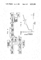
- FIG. 13 shows the fluctuation of the actually measured stroke variation characteristics
- FIG. 14 shows the state in which the actually measured stroke variation characteristics is deviated from the reference stroke variation characteristics due to the occurrence of a sticking of the valve.
- the main steam stop valve has a main valve casing 1 provided with an upper cover 2 and accommodates a strainer 3, with main valve casing 1 incorporating therein a valve seat 5.
- the main steam stop valve has a valve body 4 integral with a valve rod 6 slidably held by bushes 8a, 8b and 8c, disposed in a housing such that the valve body 4 is movable into contact with and away from the valve seat 5.
- the valve body 4 is adapted to be driven by a driving mechanism which includes a hydraulic actuator 9, hydraulic cylinder 10, piston 11, slidably received by the cylinder 10 and a piston rod 12 connected to the piston 11, with piston rings 11a being fitted around the piston 11.
- the piston rod 12 is slidably held by a bush 8d fitted in a bore formed in the hydraulic actuator 9, and is coupled to the valve rod 6 by means of a coupling 13.
- the piston 11 is normally urged downwardly by a compression spring 14.
- the above described main steam stop valve often encounters various troubles, one of which is the sticking of the valve explained hereinabove.
- the sticking of the main steam stop valve is caused by a seizure, scuffing or the like extraordinary state of sliding between the valve rod 6 and the bushes 8a to 8c which takes place when the appropriate gap therebetween is lost.
- the failure in maintaining the appropriate gap is attributable to various reasons such as generation and depositon of scale, invasion of foreign matter, bending of the valve rod, centering failure in the coupling 13 and so forth.
- the cause of the valve stick does not always reside in the main steam stop valve but in some cases resides in the hydraulic actuator 9. Namely, an extraordinary increase of the gap beween the piston 11 and the cylinder 10, failure in the piston ring 11a and failure in the bush 8d may lead to the valve sticking.
- the valve sticking does not take place suddenly but is preceded by symptoms such as an unsmooth sliding motion, vibration or chattering with such symptoms being gradually developed to finally cause the sticking of the valve.
- symptoms such as an unsmooth sliding motion, vibration or chattering with such symptoms being gradually developed to finally cause the sticking of the valve.
- it is essential to detect the slight symptom or abnormality in the valve operation and to take a suitable countermeasure at an early stage.
- valve test which is conducted once a day by driving each valve from a fully open position to a fully closed position and vice versa by means of a manual testing system shown in FIG. 2 an to permit the operator to visually check the valve for any abnormality in the valve operation.
- the upper chamber of a hydraulic cylinder 10 is normally communicated with an oil tank 16 through a drain circuit 15.
- a control oil is supplied by a control oil supply device 17 into the lower piston chamber in the hydraulic cylinder 10
- the piston 11 is moved upward overcoming the force of the compression spring 14 to move the valve body 4 away from the valve seat 5.
- a relay damp valve 89 for an emergency tripping of the valve is normally closed by being pushed up by the oil supplied from the emergency tripping oil supply device 18. As the supply of the emergency tripping oil is terminated, the relay damp valve 89 is opened to permit the lower piston chamber in the hydraulic cylinder 10 to be communicated with the oil tank 16 so that the valve body 4 is brought to the closing position instantaneously.
- the daily test of valve operation is conducted in the following manner.
- test solenoid valve 91 is opened to permit compressed air 19 to flow into the lower piston chamber of the pneumatic cylinder 96 to actuate a lever 20. Consequently, a test pilot valve 90 is moved upward to intercept the control oil from the control oil supply device 17. As a result, the piston 11 in the hydraulic cylinder 10 is lowered to bring the valve body 4 into the closing position. Then, as the switch 48 is opened, the valve body 4 is moved to the open position by a reversing operation of the test deice. During the driving of the valve from the open position to the closed position and vice versa, the operator visually checks the motion of the valve for any abnormality.
- This inspection method is effective only to heavy or distinctive abnormalities in the valved motion visually or audibly detactable by the operator and, consequently, there is a fear that even a skilled and trained operator may overlook a slight symptom of trouble in the valve device.
- a turbine valve device diagnostic apparatus is combined with the main steam stop valve and the manual valve testing system described hereinabove for observing and diagnosing any symptom of a sticking of the main steam stop valve. More specifically, as shown in FIG.
- the diagnostic apparatus includes a pressure sensor 70, attached to the hydraulic cylinder 10, for detecting the hydraulic pressure in the latter, a position sensor 92 connected through a lever device 21 to the coupling 13 interconnecting the valve rod 6 and the piston rod 12 so as to detect the position or displacement of the valve body 4, a limit switch 51 hereinafter referred to as a fully open detection limit switch, for detecting the valve body 4 in the fully open position and a limit switch 52, hereinafter referred to as a fully closed detection limit switch, for detecting the valve body 4 in the full close position.
- a pressure sensor 70 attached to the hydraulic cylinder 10, for detecting the hydraulic pressure in the latter
- a position sensor 92 connected through a lever device 21 to the coupling 13 interconnecting the valve rod 6 and the piston rod 12 so as to detect the position or displacement of the valve body 4
- a limit switch 51 hereinafter referred to as a fully open detection limit switch
- a limit switch 52 hereinafter referred to as a fully closed detection limit switch
- the diagnostic apparatus has a digital input circuit 41 adapted to receive the output signals from the fully open detection lmit switch 51 and the fully closed detection limit switch 52, as well as the output from the test switch 48.
- the hydraulic pressure in the hydraulic cylinder 10 is detected by the pressure sensor 70 and is converted by a signal converter 71 into a voltage or electric current signal of a level corresponding to the hydraulic pressure.
- the mechanical motion of the position sensor 92 is changed by a signal converter 55 into a voltage or electric current signal of a level corresponding to the stroke of the valve.
- the voltage or electric current signals thus obtained are delivered to an analog input circuit 40 and are processed by a microcomputer 42.
- the result of the processing performed by the microcomputer 42 is put on display by a display lamp 45 through a digital output circuit 44 and outputted to a printer 46 or a CRT display device 47.
- the data obtained in the past operation are all stored in an external memory device and are read out as required.
- the processing unit in the diagnostic apparatus of the invention the mechanical motion of the position sensor 92 detecting the position of the valve is transmitted to the signal converter 55 while the hydraulic pressure in the hydraulic cylinder is transmitted to the signal converter 71 through the pressure sensor 70.
- the mechanical motion and the hydraulic pressure are changed into voltage or electric current signals by respective signal converters 55, 71.
- the signals derived from these signal converters are delivered to a data storage device 56 through a gate 51a which is adapted to be opened and closed by the fully open detection limit switch 51 and the fully closed detction limit switch 52. More specifically, the gate 51a is closed when both of the limit switches 51 and 52 are opened but is opened if either one of these limit switches is closed.
- the hydraulic pressure signal is fed fom the signal converter 71 to the data storage device 56, while the stroke signal representative of the displacement or stroke of the valve body is delivered by the signal converter 55 to a stroke synchronizer 60.
- the stroke synchronizer 60 is adapted to deliver a signal to a timing controller 57 at each time the actually obtained stroke signal reaches a hydraulic signal sampling stroke of a predetermined interval, and a timing signal is inputted to the data storage device 56 in accordance with the signal delivered to the timing controller 57.
- the data storage device 56 intermittently stores the actually measured hydraulic pressure at a constant valve stroke interval, i.e. at each time the displacement of the valve body reaches a predetermined value or distance.
- the data storage device 56 delivers its content to an offset computing device 63.
- a reference value computing device 61 computes the reference hyraulic pressure value at a predetermined hydraulic pressure sampling stroke interval, and delivers the result of the computation to a reference value storage device 62, the output of which is fed to the offset computing device 63.
- the offset computing device Upon receipt of the hydraulic presure signal and the reference signal, the offset computing device computes the difference therebetween, i.e. the offset of the actual value from the reference value.
- the diagnostic apparatus of the first embodiment functions to store the reference values and is constructed to compare the electric signals from respective sensors with the reference value to permit the computation of the offset from the reference value.
- the diagnostic apparatus of the first embodiment has a reference offset value memory device 65 for prestoring the reference offset values, an offset comparator 64 for comparing the offset value computed by the offset computing device 63 with the reference offset value read out from the reference offset value memory device 65, and a judging device 66 for judging whether there is any abnormality of the valve motion in accordance with the result of the comparison.
- the diagnostic apparatus of this embodiment is constructed to store the reference offset values and to evaluate and judge the computed offset value through comparison with the reference offset values.
- the output from the offset judging device 66 is fed to a display device 67 adapted to display the result of the judgement performed by the offset judging device 66.
- valve device diagnostic apparatus of this embodiment operates in a manner explained hereinunder.
- the valve body 4 is actuated to close and open, respectively, as the test device switch 48 shown in FIG. 2 is closed and opened.
- the fully open detection limit switch 51 is opened when the valve body 4 starts to move in the closing direction
- the fully closed detection limit switch 52 is closed when the valve body 4 is completely seated on the valve seat after travelling the full stroke from the full open position to the full close position.
- the position sensor 92 moves following up the movement of the valve body 4 when the latter is moved in the closing direction.
- a switch 51a associated with the limit switch 51 is closed so that an electric signal representing the positon of the valve body, produced by the signal converter 55, is delivered to the stroke synchronizer 60.
- the pressure signal representing the hydraulic pressure in the hydraulic cylinder corresponding to the instant valve body position is delivered in the form of an electric signal from the signal converter 71 to the data storage device 56. Since the capacity of the data storage device 56 is limited, it is necessary to sample the data at a predetermined interval of the stroke. Thus, the signals thus obtained are intermittently delivered to the data storage device 56 at a predetermined stroke interval.
- the stroke synchronizer 60 operats to deliver a storage timing signal to the timing controller 57 at each time the measured stroke value reaches a predetermined pressure sampling stroke value, and the above-mentioned signal is delivered to the data storage device 56 from the timing controller 57. Consequently, the hydraulic pressure signals are sampled at a predetermined stroke interval and the sampled hydraulic pressure signals are stored in the data storage device 56. The supply of the hydraulic pressure signal is terminated when the full close detrection limit switch 52 is turned on, so that the delivery of the data to the data storage device 56 is ceased. In FIG.
- the abscissa represents the closing stroke (%) of the valve body while the ordinate represents the fluctuation of hydaulic pressure (Kg/cm 2 g) in the hydraulic pressure for driving the valve body.
- the full-line curve 21 shows the hydraulic pressures stored during the test valve driving in the closing direction. Although this curve is continuous, this curve actually consists of numerous dots because the hydraulic pressure is sampled at a predetermined stroke interval.
- the reference value computing device 61 computes the reference characteristics at the predetermined hydraulic pressure sampling stroke interval. The computation is made to determine the reference value in accordance with the following formula (1), neglecting the largely fluctuating portion of the reference characteristics which tend to cause an erroneous judgement.
- the reference hydraulic pressure is computed in accordance with the formula (1) at the constant sampling interval to determine a reference hydraulic pressure curve 22. These reference hydraulic pressures are stored in a reference value storage device 62. Subsequently, an offset of the actually measured value 21 from the reference value 22 is determined by the offset computing device 63 in accordance with the following formula (2).
- the abscissa represents the closing valve stroke (%) while the ordinate represents the offset of the hydraulic pressure (%) in the hydraulic cylinder for driving the valve body.
- Positive offset is shown above the horizontal line representing zero offset, while negative offset is shown below the same line.
- the offset levels ⁇ 10% are determined as valve sticking symptom levels, while the offset levels ⁇ 20% are determined as being alarming levels.
- the sticking symptom levels and alarming levels can be selected at any other levels than mentioned above, in accordance with experience and data accumulated in the past.
- the curve 23 substantially coincides with the horizontal line representintg the zero offset. Thus, the valve device is judged to be almost in a perfect condition when the hydraulic pressure offset values follow this curve 23.
- the curve 24 involves a peak which exceeds the stick symptom level athough it is still below the alarming level.
- the curve 25 exhibits a peak value which exceeds the alarming level. This means that the sticking of the valve will take place very soon, although it has not yet actually occurred.
- the reference offset value memory device 65 shown in FIG. 4 stores the offset level of 10% as the stick symptom level and offset level of 20% as the alarming level. These levels are compared in the offset comparator 64 with the offset values computed by the offset computing device 63 and the result of the comparison is classified by the offset judging device 6 into the folowing three classes: namely, normal state (below 10%), sticking symptom state (between 10% and 20%) and dangerous state (above 20%). The result of the classification is displayed on the display device 67.
- the comparing and computing devices incorporated in the diagnostic appratus of this embodiment functions to store the reference offset value and to judge the offset value through comparison with the reference offset value. It is, therefore, possible to fully automatically judge whether there is any abnormality in the valve device without requiring any human judgement.
- the operator can be aware of any symptom of abnormality or trouble without any specific skill or mental burden, if a suitable instrument such as alarming lamp, buzzer, printer or the like is provided for displaying the result of the judgement as in the case of the described embodiment.
- the reference hydraulic pressure is computed at a constant stoke interval in synchronism with the actual measurement of the hydraulic pressure.
- This is not exclusive and the arrangement may be such that the stroke values of the valve in the normal state of the valve device are determined in accordance with experience values and reference pressure values corresponding to the stroke values are beforehand computed and memorized for the comparison with the actually measured pressures.
- pressure datum are stored in the data storage device 56 in the period after the fully open detection limit switch 51 or the fully closed detection limit switch 52 senses the start of movement of the valve body 4 until the fully open or fully closed state of the valve is detected by the limit switch, and the rate of fluctuation of the pressure value is computed by a fluctuation rate computing device 80, the result of which is stored in a fluctuation rate storage device 81.
- reference fluctuation rates are prestored in a reference fluctuation rate storage device 82.
- the computed fluctuation rate is then compared with the reference fluctuation rate read out from the storage device 82, by means of a fluctuation rate comparator 83.
- the result of the comparison is judged by a fluctuation rate judging device 84 which delivers a signal representing the result of the judgement to the display device 67.
- the symptom of a valve sticking can be detected also by observing how the hydraulic pressure is changed in relation to time, as in the third embodiment shown in FIG. 8. More particularly, in FIG. 8, the signal from the pressure sensor 70 is fed to the signal converter 71 the output of which is delivered to the data storage device 56 through a switch 51a which is adapted to be opened and closed by the operation of the fully open detection limit switch 51 and the fully closed detection limit switch 52. When the switch 51a takes the closed state, the signal representative of the actually measured hydraulic pressure coming from the signal converter 71 is stored in the data storage device 56. At the same time, a time signal is delivered by a timer 54 to the timing controller 57 which functions to make the data storage device 56 periodically store the input from the signal converter 71 upon receipt of the time signal.
- a time signal from another timer 54' is delivered to a full stroke time measuring device 58 through the switch 51a which is opened and closed by the operation of the full open detection limit switch 51 and the fully closed detection limit switch 52.
- the measuring device 58 measures the time length required for the valve member to travel the whole stroke length from the full open position to the full close position or from the full close position to the full open position.
- the result of the measurement of time is stored in the full stroke time storage device 59.
- the stored signal is then delivered to a reference value computing device 61 which computers the refernce hydraulic pressure using the full stroke time as a parameter, the result of which is stored in the reference value storage device 62.
- the offset of the actually measured pressure value stored in the data storage device 56 is compared by an offset computing device 63 with the reference hydraulic pressure value stored in the reference value storage device 62.
- the computed offset is then compared by the offset comparator 64 with the reference value which is beforehand stored in the reference offset value memory device 65.
- the result of the comparison made in the offset comparator 64 is fed into the offset judging device 66 which judges the state of operation of the valve device. The result of the judgement is put on display on the display device 67.
- the valve device apparatus has a position sensor 92 connected through a lever device 21 to the coupling 13 between the valve rod 6 and the piston rod 12 and adapted to detect the position or movement of the valve body 4, a limit switch 51 for detecting that the valve body is in the fully open position and a limit switch 52 adapted for detecting that the valve body 4 is in the fully closed position.
- the valve device diagnostic apparatus is combined with a main steam stop valve and manual valve testing device which are of the same type as those explained before in connection with FIGS. 1 and 2.
- the diagnostic apparatus of FIG. 9 is devoid of the pressure sensor 70 which is used in the first embodiment shown in FIG. 2 for sensing the hydraulic pressure in the hydraulic cylinder 10.
- the diagnostic apparatus of FIG. 9 includes a digital input circuit 41 for receiving the output signals from the fully open detection limit switch 51, fully closed detection limit switch 52 and the test device operation switch 48.
- the output signal from the position sensor 92 is converted by a signal converter 55 into a voltage or electric current signal corresponding to the motion or stroke of the valve body, and is fed to an analog input circuit 40.
- the signals delivered to the analog input circuit 40 and the digital inout circuit 41 are processed by a microcomputer 42, and the result of the processing is sent through a digital output circuit 44 to a display lamp 45 for the display.
- the result of the processing is also delivered to a printer 46 or a CRT display device 47.
- the data obtained in the past are stored in an external memory device 43 and are read out as required.
- the construction of the processing device incorporated in the embodiment of FIG. 9 will be described hereinunder with reference to FIG. 11.
- the movement or stroke travelled by the valve rod 6 is sensed by the position sensor 92 and is delivered to the signal converter 55 the output of which is delivered to a data storage device 56 through a switch 51a which is adapted to be opened and closed by the operation of the fully open detection limit switch 51 and the fully closed detection limit switch 52.
- switch 51a is kept closed, the stroke signal derived from the signal converter 55 is delivered to the data storage device 56.
- a storage timing controller 57 delivers, upon receipt of a signal from a m sec timer 54, a storage timing signal to the data storage device 56.
- the signal from the converter 55 is stored in the data storage device 56 in accordance with this storage timing signal. Simultaneously, a signal representative of the full stroke time is fed to the full stroke time storage device 59. Namely, a signal from another m sec timer 54' is delivered to and stored in the full stroke time storage device 59 through the switch 51a which is opened and closed by the full open detection limit switch 51 and the full close detection limit switch 52 and then through a full stroke time measuring device 58. The full stroke time stored in the full stroke time storage device 59 is fed to a reference value coefficient computing device 35 and the result of the computation performed by the device 35 is delivered to the reference value computing device 61.
- the result of the computation performed by the device 61 is delivered to a reference value storage device 62 and then fed to an offset computing device 63.
- the offset computing device 63 receives also the data derived from the data storage device 56. Then, the output from the offset computing device 63 and the refernce offset value memorized in the refernce offset value memory device 65 are fed to an offset comparator 64 the output of which is delivered to the display device 67 through the offset judging device 66.
- the diagnostic apparatus of the embodiment of FIG. 9 operates in a manner explained hereinunder.
- the test device operation switch 48 is closed, the test device solenoid valve 91 is opened to permit compressed air to enter a pneumatic cylinder 96 to thereby drive a relay piston so that the valve body 4 of the main steam stop valve 4 starts to close.
- the diagnostic apparatus is prepared for the diagnostic operation, and the number of the valve to be tested is memorized in the apparatus.
- the fully open detection limit switch 51 is opened to close the associated switch 51a so that the signals from the position sensor 92 and the signal converter 55 are fed to the data storage device 56.
- the full stroke time measuring device 58 is electrically connected to the m sec timer 54' to start the time measurement. Since the capacity of the data storage device 56 is limited, the datum have to be sampled at a constant interval. Therefore, the obtained signals are transmitted to the data storage device 56 at a predetermined time interval. Namely, the signal coming from the m sec timer 54 is integrated in the storage timing controller 57 and the above-mentioned signal is issued at each time the integrated value raches a predetermined value. Thus, the stroke signals are fed to the data storage device 56 at a predetermined time interval during the movement of the valve body from the full open position to the full close position.
- the abscissa represents the time (second) while the ordinate represents the stroke value (%).
- a full-line curve 21 shows the actually measured stroke values mentioned above. Needless to say, the curve 21 consists of a numerous dots because the values constituting this curve are obtained by sampling made at a predetermined time interval, although it appears as a continuous curve.
- the full stroke time To is the time elapsed until the stroke value becomes 100%, i.e. until the time (reference numeral 30) at which the valve member is moved to the full close position.
- the coefficient computing device 35 computes the coefficient of a reference value computation formula and, with this coefficient, reference values are computed by the reference value computing device 61 to draw a reference value curve which is shown in FIG. 12 bearing a reference numeral 22.
- the function for computing the reference value curve is represented by the following formula (3).
- K 1 ,K 2 ,K 3 ,K 4 ,K 5 : . . . reference value computation coefficients.
- reference stroke is determined for each sampling interval of the actually measured stroke curve 21 and is stored in the reference stroke value storage device 62.
- One of the features of the embodiment of FIG. 9 resides in the computation of the reference stroke.
- the stroke of the main steam stop valve fluctuates more or less even when the same is in normal state. This means that the reference values are not always constant. Namely, the curve 21 representing the actually measured stroke values is fluctuated as shown in FIG. 13, followed by a fluctuation in the full stroke time as To', To", To'", To"".
- the actually measured full stroke time To is used as the parameter in the computation of the reference stroke curve. It is, therefore, possible to obtain a reference stroke curve corresponding to the actually measured stroke time, so that the above-mentioned fluctuation is advantageously negated.
- the offset of the actually measured value 21 from the reference value 22 is determined by the offset computing device 63 in accordance with the following formula (4).
- the result of computation of the offset is shown in FIG. 14. More specifically, the abscissa represents the time (sec) while the ordinate represents the stroke offset (%). Positive offset (%) is shown above a horizontal line representing the zero offset while negative offset (%) is shown below the same horizontal line.
- the motion of the valve body is started from the fully open position 31 and is ended at fully closed position 30.
- Three offset curves are drawn in FIG. 14. The offset values are compared in the offset comparator 64 with predetermined reference offset values such as alarming level or valve sticking symptom level, and is judged by means of the offset judging device 66. For instance, the offset curve 26 shown in FIG. 14 has a peak value exceeding the alarming level 33. This means that there is a large possibility of stick of valve in the very near future.
- the curve 27 has a peak value which is below the alarming level 33 but exceeds a symptom level 29. This means that there is a symptom of a valve sticking.
- the offset curve 28 shows the offset values as obtained when the valve device is in normal state. The judgement is made by the offset judging device 66 and the result of the judgement is displayed on the display device 67.
- the test device switch 48 is turned on to move the valve body from the fully open position to the fully closed position. The valve body is returned to the fully open position as the test device switch 48 is turned off. The detection of symptom of valve sticking can be made equally during the movement of the valve body from the fully closed position to the fully open position.
Abstract
Description
g(x)=a+b.X+c.X.sup.2 +d.X.sup.3 +e.X.sup.4 +f.X.sup.5 (1)
Δ(x)=f(x)-g(x) (2)
g(t)=100+AK.sub.1 t+BK.sub.2 t.sup.2 +CK.sub.3 t.sup.3 +DK.sub.4 t.sup.4 +EK.sub.5 t.sup.5 (3)
Δ(t)=f(t)-g(t) (4)
Claims (12)
Applications Claiming Priority (4)
| Application Number | Priority Date | Filing Date | Title |
|---|---|---|---|
| JP56122973A JPS5825502A (en) | 1981-08-07 | 1981-08-07 | Diagnostic device of turbine valve |
| JP56-122973 | 1981-08-07 | ||
| JP12297281A JPS5825501A (en) | 1981-08-07 | 1981-08-07 | Diagnostic device of turbine valve |
| JP56-122972 | 1981-08-07 |
Publications (1)
| Publication Number | Publication Date |
|---|---|
| US4523286A true US4523286A (en) | 1985-06-11 |
Family
ID=26460003
Family Applications (1)
| Application Number | Title | Priority Date | Filing Date |
|---|---|---|---|
| US06/405,350 Expired - Lifetime US4523286A (en) | 1981-08-07 | 1982-08-05 | Apparatus for making diagnosis of valve device in turbine system |
Country Status (2)
| Country | Link |
|---|---|
| US (1) | US4523286A (en) |
| CA (1) | CA1190622A (en) |
Cited By (81)
| Publication number | Priority date | Publication date | Assignee | Title |
|---|---|---|---|---|
| US4590963A (en) * | 1985-04-03 | 1986-05-27 | Combustion Engineering Co., Inc. | Method of and apparatus for determining the position of a movable member |
| US4690003A (en) * | 1983-07-19 | 1987-09-01 | Charbonneau & Godfrey Associates | Motor operated valve analysis and testing system |
| US4693113A (en) * | 1983-07-19 | 1987-09-15 | Charbonneau And Godfrey Associates | Motor operated valve analysis and testing system |
| US4694390A (en) * | 1985-06-28 | 1987-09-15 | Electric Power Research Institute, Inc. | Microprocessor-based control and diagnostic system for motor operated valves |
| US4695965A (en) * | 1983-02-22 | 1987-09-22 | Toshiba Kikai Kabushiki Kaisha | Monitoring data display method and device |
| US4705459A (en) * | 1984-11-15 | 1987-11-10 | Dowell Schlumberger Incorporated | Method of observing the pumping characteristics of a positive displacement pump |
| US4714005A (en) * | 1986-07-28 | 1987-12-22 | Vickers, Incorporated | Power transmission |
| WO1988008497A1 (en) * | 1987-04-22 | 1988-11-03 | Ronald Walko | Limit switch replacement system and universal bracket |
| US4792911A (en) * | 1986-01-17 | 1988-12-20 | Westinghouse Electric Corp. | Diagnostic apparatus for an electric generator seal oil system |
| US4816987A (en) * | 1985-06-28 | 1989-03-28 | Electric Power Research Institute, Inc. | Microprocessor-based control and diagnostic system for motor operated valves |
| EP0315391A2 (en) * | 1987-10-30 | 1989-05-10 | Westinghouse Electric Corporation | Online valve diagnostic monitoring system |
| US4896562A (en) * | 1988-03-24 | 1990-01-30 | Limitorque Corporation | Valve actuator differential worm planetary gear drive |
| US4976144A (en) * | 1988-08-25 | 1990-12-11 | Fisher Controls International, Inc. | Diagnostic apparatus and method for fluid control valves |
| WO1990015948A1 (en) * | 1989-06-20 | 1990-12-27 | Combustion Engineering, Inc. | Pneumatic operated valve data acquisitioner |
| EP0418083A2 (en) * | 1989-09-14 | 1991-03-20 | International Control Automation Finance S.A. | Control instrument condition sensing |
| US5008841A (en) * | 1989-07-28 | 1991-04-16 | Liberty Technology Center, Inc. | Non-invasive system and method for inspection of valves |
| US5033010A (en) * | 1988-11-16 | 1991-07-16 | Sundstrand Corporation | Turbine engine monitoring system |
| US5086273A (en) * | 1990-04-20 | 1992-02-04 | Liberty Technology Center, Inc. | A.C. electromagnetic system for determining position of an encased movable electrically conductive element |
| US5109692A (en) * | 1988-08-25 | 1992-05-05 | Fisher Controls International Inc. | Diagnostic apparatus and method for fluid control valves |
| US5140263A (en) * | 1990-04-20 | 1992-08-18 | Liberty Technology Center, Inc. | System for determining position of an internal, movable conductive element |
| US5154080A (en) * | 1986-10-29 | 1992-10-13 | Westinghouse Electric Corp. | Integrated check valve testing system |
| US5172311A (en) * | 1988-11-11 | 1992-12-15 | Mannesmann Rexroth Gmbh | Electrical amplifier for controlling valves |
| WO1992022764A1 (en) * | 1991-06-10 | 1992-12-23 | Keystone International Holdings Corp. | Method and apparatus for monitoring recirculation control system performance |
| AU632759B2 (en) * | 1988-08-25 | 1993-01-14 | Fisher Controls International Inc. | Diagnostic apparatus and method for fluid control valves |
| US5197328A (en) * | 1988-08-25 | 1993-03-30 | Fisher Controls International, Inc. | Diagnostic apparatus and method for fluid control valves |
| US5231469A (en) * | 1990-12-27 | 1993-07-27 | Combustion Engineering, Inc. | Laser position indicator for valve stem |
| US5261437A (en) * | 1991-06-10 | 1993-11-16 | Keystone International Holdings Corp. | Method and apparatus for monitoring and analyzing recirculation control system performance |
| US5329956A (en) * | 1993-05-28 | 1994-07-19 | Combustion Engineering, Inc. | Pneumatic operated valve stroke timing |
| US5433245A (en) * | 1993-08-16 | 1995-07-18 | Westinghouse Electric Corporation | Online valve diagnostic monitoring system having diagnostic couplings |
| GB2290154A (en) * | 1994-06-02 | 1995-12-13 | Mannesmann Ag | Determining condition of a control valve |
| DE19620468A1 (en) * | 1996-05-21 | 1997-11-27 | Herion Technomatic Ag Aesch | Safety valve incorporating pressure sensors linked to computer |
| US5767780A (en) * | 1993-09-22 | 1998-06-16 | Lockheed Martin Energy Research Corporation | Detector for flow abnormalities in gaseous diffusion plant compressors |
| US5966679A (en) * | 1995-10-30 | 1999-10-12 | Fisher Controls International, Inc. | Method of and apparatus for nonobtrusively obtaining on-line measurements of a process control device parameter |
| US6035878A (en) * | 1997-09-22 | 2000-03-14 | Fisher Controls International, Inc. | Diagnostic device and method for pressure regulator |
| US6119515A (en) * | 1996-10-21 | 2000-09-19 | Samson Aktiengesellschaft | Method and apparatus for monitoring actuators |
| US6131609A (en) * | 1996-06-11 | 2000-10-17 | Neles Controls Oy | Method for surveying the condition of a control valve, and a valve apparatus |
| US6192321B1 (en) | 1997-09-29 | 2001-02-20 | Fisher Controls International, Inc. | Method of and apparatus for deterministically obtaining measurements |
| US6267138B1 (en) * | 1997-06-05 | 2001-07-31 | Samson Aktiengesellschaft | Method and means for monitoring a control apparatus |
| US20020040284A1 (en) * | 1997-09-29 | 2002-04-04 | Junk Kenneth W. | Detection and discrimination of instabilities in process control loops |
| US6386229B1 (en) * | 1999-07-16 | 2002-05-14 | Smc Corporation | Method and device for managing operation of solenoid valve |
| US6453261B2 (en) | 1997-07-23 | 2002-09-17 | Dresser, Inc. | Valve positioner system |
| US6466893B1 (en) | 1997-09-29 | 2002-10-15 | Fisher Controls International, Inc. | Statistical determination of estimates of process control loop parameters |
| US6557400B2 (en) | 2001-03-30 | 2003-05-06 | Honeywell International Inc. | Surge bleed valve fault detection |
| WO2003038236A1 (en) * | 2001-10-30 | 2003-05-08 | Baker Hughes Incorporated | Method and system for controlling a downhole flow control device using derived feedback control |
| US20030154051A1 (en) * | 2002-02-13 | 2003-08-14 | Kabushiki Kaisha Toshiba | Method and system for diagnosis of plant |
| US20040129317A1 (en) * | 2001-04-12 | 2004-07-08 | Neil Bevan | Rotary bleed valve assembly |
| US6814096B2 (en) * | 2000-12-15 | 2004-11-09 | Nor-Cal Products, Inc. | Pressure controller and method |
| US20040228173A1 (en) * | 2003-02-14 | 2004-11-18 | Larry Schoonover | Method, system and storage medium for performing online valve diagnostics |
| US20050257618A1 (en) * | 2004-05-21 | 2005-11-24 | Michael Boken | Valve monitoring system and method |
| US20060009338A1 (en) * | 2004-07-12 | 2006-01-12 | Kirkpatrick John T | Apparatus and process for cups having a metallized/holographic PET film exterior |
| US20070078533A1 (en) * | 2005-10-04 | 2007-04-05 | Fisher-Rosemount Systems, Inc. | Process model identification in a process control system |
| WO2007061424A1 (en) * | 2005-11-22 | 2007-05-31 | Norgren, Inc. | Valve with sensor |
| US20070142936A1 (en) * | 2005-10-04 | 2007-06-21 | Fisher-Rosemount Systems, Inc. | Analytical Server Integrated in a Process Control Network |
| US7283894B2 (en) | 2006-02-10 | 2007-10-16 | Dresser, Inc. | System and method for fluid regulation |
| US20080015796A1 (en) * | 2006-07-05 | 2008-01-17 | Stabilus Gmbh | Piston-cylinder unit with diagnostic unit |
| US7334606B1 (en) | 2003-01-24 | 2008-02-26 | Hurley Lyndon J | Valve tester suspension enhancements |
| US20080163936A1 (en) * | 2007-01-05 | 2008-07-10 | Dresser, Inc. | Control Valve and Positioner Diagnostics |
| US7415376B1 (en) * | 2003-01-24 | 2008-08-19 | Hurley Lyndon J | Valve tester control enhancements |
| US20080281534A1 (en) * | 2007-05-07 | 2008-11-13 | Hurley Lyndon J | Flow testing system for fluid networks |
| WO2009121965A1 (en) * | 2008-04-03 | 2009-10-08 | Leanvent Aps | Flow control valve |
| US7703473B1 (en) | 2003-01-24 | 2010-04-27 | Hurco Technologies, Inc. | Valve tester suspension assembly |
| US7983869B1 (en) | 2007-05-07 | 2011-07-19 | Hurley Lyndon J | Flow testing system for fluid networks |
| US8036760B2 (en) | 2005-10-04 | 2011-10-11 | Fisher-Rosemount Systems, Inc. | Method and apparatus for intelligent control and monitoring in a process control system |
| US20110252895A1 (en) * | 2010-04-20 | 2011-10-20 | Joerg Kiesbauer | Method for determining an operating position of an open/closed-valve and field device |
| US20120048396A1 (en) * | 2010-08-31 | 2012-03-01 | Kaneko Sangyo Co., Ltd. | Cutoff valve control apparatus |
| WO2012056291A2 (en) * | 2010-10-28 | 2012-05-03 | Ormat Technologies Inc. | Diagnostic system and method for an essential turbine valve |
| CN101943291B (en) * | 2005-11-22 | 2013-12-04 | 诺格伦公司 | Valve with sensor |
| US20130340430A1 (en) * | 2012-06-20 | 2013-12-26 | Eric David Peters | Systems and methods for a hydraulically actuated engine valve |
| WO2014055813A1 (en) * | 2012-10-05 | 2014-04-10 | Fisher Controls International Llc | Methods and apparatus for process device calibration |
| US20150034846A1 (en) * | 2013-08-02 | 2015-02-05 | Yi-Ming Fan | Automatic detecting and repairing wisdom valve apparatus |
| CN105587926A (en) * | 2016-01-28 | 2016-05-18 | 太仓市高泰机械有限公司 | Automatic monitoring type hydraulic safety valve |
| EP3098450A1 (en) * | 2015-05-29 | 2016-11-30 | Mitsubishi Heavy Industries, Ltd. | Method and apparatus for diagnosing a hydraulic machine, power generating apparatus of renewable-energy type, and method of diagnosing the same |
| US20170114726A1 (en) * | 2015-10-22 | 2017-04-27 | United Technologies Corporation | Apparatus and method for controlling and monitoring an electro-hydraulic servovalve |
| US9719630B1 (en) | 2016-02-08 | 2017-08-01 | Hurco Technologies, Inc. | Pivoting support assembly |
| US20170219119A1 (en) * | 2014-08-01 | 2017-08-03 | Chargepoint Technology Limited | Operator feedback of valves |
| US9835285B1 (en) | 2016-02-08 | 2017-12-05 | Hurco Technologies, Inc. | Pivoting support assembly |
| WO2018209564A1 (en) * | 2017-05-16 | 2018-11-22 | General Electric Company | Valve remaining life estimation method and system thereof |
| EP2886916B1 (en) * | 2013-12-20 | 2019-02-20 | IMI Hydronic Engineering International SA | A valve and a method of operating a valve |
| WO2020007923A1 (en) * | 2018-07-03 | 2020-01-09 | Samson Aktiengesellschaft | Diagnosis of possible causes of changes in a control valve |
| US20220082027A1 (en) * | 2019-01-24 | 2022-03-17 | Safran Helicopter Engines | Method for monitoring the operating state of a system for positioning variable-geometry members of a turbomachine |
| US20230258281A1 (en) * | 2017-11-29 | 2023-08-17 | Fujikin Incorporated | Valve, Abnormality Diagnosis Method of Valve |
Citations (4)
| Publication number | Priority date | Publication date | Assignee | Title |
|---|---|---|---|---|
| US4029122A (en) * | 1976-03-11 | 1977-06-14 | Westinghouse Electric Corporation | Apparatus and method for determining friction forces in position modulated valves |
| US4090065A (en) * | 1972-04-26 | 1978-05-16 | Westinghouse Electric Corp. | System and method for operating a steam turbine with protection provisions for a valve positioning contingency |
| US4274438A (en) * | 1979-02-21 | 1981-06-23 | Westinghouse Electric Corp. | Method of diagnostic valve testing |
| US4404637A (en) * | 1981-04-30 | 1983-09-13 | Phillips Petroleum Company | Process control system |
-
1982
- 1982-08-05 US US06/405,350 patent/US4523286A/en not_active Expired - Lifetime
- 1982-08-06 CA CA000408887A patent/CA1190622A/en not_active Expired
Patent Citations (4)
| Publication number | Priority date | Publication date | Assignee | Title |
|---|---|---|---|---|
| US4090065A (en) * | 1972-04-26 | 1978-05-16 | Westinghouse Electric Corp. | System and method for operating a steam turbine with protection provisions for a valve positioning contingency |
| US4029122A (en) * | 1976-03-11 | 1977-06-14 | Westinghouse Electric Corporation | Apparatus and method for determining friction forces in position modulated valves |
| US4274438A (en) * | 1979-02-21 | 1981-06-23 | Westinghouse Electric Corp. | Method of diagnostic valve testing |
| US4404637A (en) * | 1981-04-30 | 1983-09-13 | Phillips Petroleum Company | Process control system |
Cited By (147)
| Publication number | Priority date | Publication date | Assignee | Title |
|---|---|---|---|---|
| US4695965A (en) * | 1983-02-22 | 1987-09-22 | Toshiba Kikai Kabushiki Kaisha | Monitoring data display method and device |
| US4862385A (en) * | 1983-02-22 | 1989-08-29 | Toshiba Kikai Kabushiki Kaisha | Monitoring data display device |
| US4690003A (en) * | 1983-07-19 | 1987-09-01 | Charbonneau & Godfrey Associates | Motor operated valve analysis and testing system |
| US4693113A (en) * | 1983-07-19 | 1987-09-15 | Charbonneau And Godfrey Associates | Motor operated valve analysis and testing system |
| US4705459A (en) * | 1984-11-15 | 1987-11-10 | Dowell Schlumberger Incorporated | Method of observing the pumping characteristics of a positive displacement pump |
| US4590963A (en) * | 1985-04-03 | 1986-05-27 | Combustion Engineering Co., Inc. | Method of and apparatus for determining the position of a movable member |
| US4816987A (en) * | 1985-06-28 | 1989-03-28 | Electric Power Research Institute, Inc. | Microprocessor-based control and diagnostic system for motor operated valves |
| US4694390A (en) * | 1985-06-28 | 1987-09-15 | Electric Power Research Institute, Inc. | Microprocessor-based control and diagnostic system for motor operated valves |
| US4792911A (en) * | 1986-01-17 | 1988-12-20 | Westinghouse Electric Corp. | Diagnostic apparatus for an electric generator seal oil system |
| WO1987007950A1 (en) * | 1986-06-23 | 1987-12-30 | Charbonneau & Godfrey Associates | Motor operated valve analysis and testing system |
| US4714005A (en) * | 1986-07-28 | 1987-12-22 | Vickers, Incorporated | Power transmission |
| US5154080A (en) * | 1986-10-29 | 1992-10-13 | Westinghouse Electric Corp. | Integrated check valve testing system |
| US5027853A (en) * | 1987-04-22 | 1991-07-02 | Electronic Technology Systems, Inc. | Limit switch replacement system and universal bracket |
| WO1988008497A1 (en) * | 1987-04-22 | 1988-11-03 | Ronald Walko | Limit switch replacement system and universal bracket |
| EP0315391A3 (en) * | 1987-10-30 | 1989-05-24 | Westinghouse Electric Corporation | Online valve diagnostic monitoring system |
| US5329465A (en) * | 1987-10-30 | 1994-07-12 | Westinghouse Electric Corp. | Online valve diagnostic monitoring system |
| EP0315391A2 (en) * | 1987-10-30 | 1989-05-10 | Westinghouse Electric Corporation | Online valve diagnostic monitoring system |
| US4896562A (en) * | 1988-03-24 | 1990-01-30 | Limitorque Corporation | Valve actuator differential worm planetary gear drive |
| US4976144A (en) * | 1988-08-25 | 1990-12-11 | Fisher Controls International, Inc. | Diagnostic apparatus and method for fluid control valves |
| US5197328A (en) * | 1988-08-25 | 1993-03-30 | Fisher Controls International, Inc. | Diagnostic apparatus and method for fluid control valves |
| AU632759B2 (en) * | 1988-08-25 | 1993-01-14 | Fisher Controls International Inc. | Diagnostic apparatus and method for fluid control valves |
| US5109692A (en) * | 1988-08-25 | 1992-05-05 | Fisher Controls International Inc. | Diagnostic apparatus and method for fluid control valves |
| US5172311A (en) * | 1988-11-11 | 1992-12-15 | Mannesmann Rexroth Gmbh | Electrical amplifier for controlling valves |
| US5033010A (en) * | 1988-11-16 | 1991-07-16 | Sundstrand Corporation | Turbine engine monitoring system |
| WO1990015948A1 (en) * | 1989-06-20 | 1990-12-27 | Combustion Engineering, Inc. | Pneumatic operated valve data acquisitioner |
| US5008841A (en) * | 1989-07-28 | 1991-04-16 | Liberty Technology Center, Inc. | Non-invasive system and method for inspection of valves |
| EP0418083A3 (en) * | 1989-09-14 | 1992-04-15 | International Control Automation Finance S.A. | Control instrument condition sensing |
| EP0418083A2 (en) * | 1989-09-14 | 1991-03-20 | International Control Automation Finance S.A. | Control instrument condition sensing |
| US5140263A (en) * | 1990-04-20 | 1992-08-18 | Liberty Technology Center, Inc. | System for determining position of an internal, movable conductive element |
| US5086273A (en) * | 1990-04-20 | 1992-02-04 | Liberty Technology Center, Inc. | A.C. electromagnetic system for determining position of an encased movable electrically conductive element |
| US5523682A (en) * | 1990-04-20 | 1996-06-04 | Liberty Technologies, Inc. | Method for determining position of an internal, movable conductive element |
| US5231469A (en) * | 1990-12-27 | 1993-07-27 | Combustion Engineering, Inc. | Laser position indicator for valve stem |
| US5261437A (en) * | 1991-06-10 | 1993-11-16 | Keystone International Holdings Corp. | Method and apparatus for monitoring and analyzing recirculation control system performance |
| WO1992022764A1 (en) * | 1991-06-10 | 1992-12-23 | Keystone International Holdings Corp. | Method and apparatus for monitoring recirculation control system performance |
| WO1994010489A1 (en) * | 1992-10-27 | 1994-05-11 | Keystone International Holdings Corp. | Method and apparatus for monitoring recirculation control system performance |
| US5329956A (en) * | 1993-05-28 | 1994-07-19 | Combustion Engineering, Inc. | Pneumatic operated valve stroke timing |
| WO1994028341A1 (en) * | 1993-05-28 | 1994-12-08 | Combustion Engineering, Inc. | Pneumatic operated valve with stroke timing |
| US5433245A (en) * | 1993-08-16 | 1995-07-18 | Westinghouse Electric Corporation | Online valve diagnostic monitoring system having diagnostic couplings |
| US5767780A (en) * | 1993-09-22 | 1998-06-16 | Lockheed Martin Energy Research Corporation | Detector for flow abnormalities in gaseous diffusion plant compressors |
| GB2290154A (en) * | 1994-06-02 | 1995-12-13 | Mannesmann Ag | Determining condition of a control valve |
| US5644948A (en) * | 1994-06-02 | 1997-07-08 | Mannesmann Aktiengesellschaft | Control valve with a drive operated by a pressure medium and a position controller |
| GB2290154B (en) * | 1994-06-02 | 1997-10-01 | Mannesmann Ag | Control valve with a pressure medium-operated drive means and a position controller |
| US5966679A (en) * | 1995-10-30 | 1999-10-12 | Fisher Controls International, Inc. | Method of and apparatus for nonobtrusively obtaining on-line measurements of a process control device parameter |
| DE19620468A1 (en) * | 1996-05-21 | 1997-11-27 | Herion Technomatic Ag Aesch | Safety valve incorporating pressure sensors linked to computer |
| US6131609A (en) * | 1996-06-11 | 2000-10-17 | Neles Controls Oy | Method for surveying the condition of a control valve, and a valve apparatus |
| US6119515A (en) * | 1996-10-21 | 2000-09-19 | Samson Aktiengesellschaft | Method and apparatus for monitoring actuators |
| US6267138B1 (en) * | 1997-06-05 | 2001-07-31 | Samson Aktiengesellschaft | Method and means for monitoring a control apparatus |
| US6453261B2 (en) | 1997-07-23 | 2002-09-17 | Dresser, Inc. | Valve positioner system |
| US6957127B1 (en) | 1997-07-23 | 2005-10-18 | Dresser, Inc. | Dynamic current-to-pneumatic converter and pneumatic amplifier |
| US6745084B2 (en) | 1997-07-23 | 2004-06-01 | Dresser, Inc. | Valve positioner system |
| US6035878A (en) * | 1997-09-22 | 2000-03-14 | Fisher Controls International, Inc. | Diagnostic device and method for pressure regulator |
| US20020040284A1 (en) * | 1997-09-29 | 2002-04-04 | Junk Kenneth W. | Detection and discrimination of instabilities in process control loops |
| US20050021298A1 (en) * | 1997-09-29 | 2005-01-27 | Fisher Controls International Llc | Detection and discrimination of instabilities in process control loops |
| US7039537B2 (en) | 1997-09-29 | 2006-05-02 | Fisher Controls Llc. | Detection and discrimination of instabilities in process control loops |
| US6466893B1 (en) | 1997-09-29 | 2002-10-15 | Fisher Controls International, Inc. | Statistical determination of estimates of process control loop parameters |
| US6192321B1 (en) | 1997-09-29 | 2001-02-20 | Fisher Controls International, Inc. | Method of and apparatus for deterministically obtaining measurements |
| US6804618B2 (en) | 1997-09-29 | 2004-10-12 | Fisher Controls International, Llc | Detection and discrimination of instabilities in process control loops |
| US6386229B1 (en) * | 1999-07-16 | 2002-05-14 | Smc Corporation | Method and device for managing operation of solenoid valve |
| US6814096B2 (en) * | 2000-12-15 | 2004-11-09 | Nor-Cal Products, Inc. | Pressure controller and method |
| US6557400B2 (en) | 2001-03-30 | 2003-05-06 | Honeywell International Inc. | Surge bleed valve fault detection |
| US20040129317A1 (en) * | 2001-04-12 | 2004-07-08 | Neil Bevan | Rotary bleed valve assembly |
| US7240691B2 (en) * | 2001-04-12 | 2007-07-10 | Bevan Engineering Limited | Rotary bleed valve assembly |
| WO2003038236A1 (en) * | 2001-10-30 | 2003-05-08 | Baker Hughes Incorporated | Method and system for controlling a downhole flow control device using derived feedback control |
| US20030154051A1 (en) * | 2002-02-13 | 2003-08-14 | Kabushiki Kaisha Toshiba | Method and system for diagnosis of plant |
| US6909990B2 (en) * | 2002-02-13 | 2005-06-21 | Kabushiki Kaisha Toshiba | Method and system for diagnosis of plant |
| US8365838B2 (en) | 2003-01-24 | 2013-02-05 | Hurco Technologies, Inc. | Valve tester suspension assembly |
| US7828017B2 (en) | 2003-01-24 | 2010-11-09 | Hurco Technologies, Inc. | Valve tester suspension enhancements |
| US8267193B1 (en) | 2003-01-24 | 2012-09-18 | Hurley Lyndon J | Valve tester suspension assembly |
| US7987923B1 (en) | 2003-01-24 | 2011-08-02 | Hurco Technologies, Inc. | Valve tester suspension assembly |
| US8967289B1 (en) | 2003-01-24 | 2015-03-03 | Hurco Technologies, Inc. | Valve tester suspension assembly |
| US7828076B1 (en) | 2003-01-24 | 2010-11-09 | Hurco Technologies, Inc. | Valve tester suspension assembly |
| US7703473B1 (en) | 2003-01-24 | 2010-04-27 | Hurco Technologies, Inc. | Valve tester suspension assembly |
| US7607624B1 (en) | 2003-01-24 | 2009-10-27 | Hurco Technologies, Inc. | Valve tester suspension assembly |
| US7455124B1 (en) | 2003-01-24 | 2008-11-25 | Hurco Technologies, Inc. | Valve tester suspension assembly |
| US20080255770A1 (en) * | 2003-01-24 | 2008-10-16 | Hurley Lyndon J | Valve tester control enhancements |
| US7334606B1 (en) | 2003-01-24 | 2008-02-26 | Hurley Lyndon J | Valve tester suspension enhancements |
| US7376529B1 (en) | 2003-01-24 | 2008-05-20 | Hurley Lyndon J | Valve tester control enhancements |
| US20080142673A1 (en) * | 2003-01-24 | 2008-06-19 | Hurley Lyndon J | Valve tester suspension enhancements |
| US7415376B1 (en) * | 2003-01-24 | 2008-08-19 | Hurley Lyndon J | Valve tester control enhancements |
| US7089086B2 (en) | 2003-02-14 | 2006-08-08 | Dresser, Inc. | Method, system and storage medium for performing online valve diagnostics |
| US20040228173A1 (en) * | 2003-02-14 | 2004-11-18 | Larry Schoonover | Method, system and storage medium for performing online valve diagnostics |
| US20050257618A1 (en) * | 2004-05-21 | 2005-11-24 | Michael Boken | Valve monitoring system and method |
| US7318350B2 (en) * | 2004-05-21 | 2008-01-15 | Michael Boken | Valve monitoring system and method |
| US20060009338A1 (en) * | 2004-07-12 | 2006-01-12 | Kirkpatrick John T | Apparatus and process for cups having a metallized/holographic PET film exterior |
| US8706267B2 (en) | 2005-10-04 | 2014-04-22 | Fisher-Rosemount Systems, Inc. | Process model identification in a process control system |
| US7444191B2 (en) | 2005-10-04 | 2008-10-28 | Fisher-Rosemount Systems, Inc. | Process model identification in a process control system |
| US20070078533A1 (en) * | 2005-10-04 | 2007-04-05 | Fisher-Rosemount Systems, Inc. | Process model identification in a process control system |
| US8036760B2 (en) | 2005-10-04 | 2011-10-11 | Fisher-Rosemount Systems, Inc. | Method and apparatus for intelligent control and monitoring in a process control system |
| US8046096B2 (en) | 2005-10-04 | 2011-10-25 | Fisher-Rosemount Systems, Inc. | Analytical server integrated in a process control network |
| US10310456B2 (en) | 2005-10-04 | 2019-06-04 | Fisher-Rosemount Systems, Inc. | Process model identification in a process control system |
| US7738975B2 (en) | 2005-10-04 | 2010-06-15 | Fisher-Rosemount Systems, Inc. | Analytical server integrated in a process control network |
| US20100228363A1 (en) * | 2005-10-04 | 2010-09-09 | Fisher-Rosemount Systems, Inc. | Analytical server integrated in a process control network |
| US20070142936A1 (en) * | 2005-10-04 | 2007-06-21 | Fisher-Rosemount Systems, Inc. | Analytical Server Integrated in a Process Control Network |
| US11487252B2 (en) | 2005-10-04 | 2022-11-01 | Fisher-Rosemount Systems, Inc. | Process model identification in a process control system |
| EP2123956A1 (en) * | 2005-11-22 | 2009-11-25 | Norgren, Inc. | Valve with sensor |
| CN101943291B (en) * | 2005-11-22 | 2013-12-04 | 诺格伦公司 | Valve with sensor |
| WO2007061424A1 (en) * | 2005-11-22 | 2007-05-31 | Norgren, Inc. | Valve with sensor |
| US8091860B2 (en) | 2005-11-22 | 2012-01-10 | Norgren Inc. | Valve with sensor |
| US7283894B2 (en) | 2006-02-10 | 2007-10-16 | Dresser, Inc. | System and method for fluid regulation |
| US20080015796A1 (en) * | 2006-07-05 | 2008-01-17 | Stabilus Gmbh | Piston-cylinder unit with diagnostic unit |
| US7890216B2 (en) | 2007-01-05 | 2011-02-15 | Dresser, Inc. | Control valve and positioner diagnostics |
| US7539560B2 (en) | 2007-01-05 | 2009-05-26 | Dresser, Inc. | Control valve and positioner diagnostics |
| US20090216350A1 (en) * | 2007-01-05 | 2009-08-27 | Dresser, Inc. | Control valve and positioner diagnostics |
| US20080163936A1 (en) * | 2007-01-05 | 2008-07-10 | Dresser, Inc. | Control Valve and Positioner Diagnostics |
| US7917324B2 (en) | 2007-05-07 | 2011-03-29 | Hurley Lyndon J | Flow testing system for fluid networks |
| US20080281534A1 (en) * | 2007-05-07 | 2008-11-13 | Hurley Lyndon J | Flow testing system for fluid networks |
| US8401811B1 (en) | 2007-05-07 | 2013-03-19 | Lyndon J. Hurley | Flow testing system for fluid networks |
| US8942947B1 (en) | 2007-05-07 | 2015-01-27 | Lyndon J. Hurley | Flow testing systems for fluid networks |
| US8805633B1 (en) | 2007-05-07 | 2014-08-12 | Lyndon J. Hurley | Flow testing system for fluid networks |
| US7983869B1 (en) | 2007-05-07 | 2011-07-19 | Hurley Lyndon J | Flow testing system for fluid networks |
| US20110041921A1 (en) * | 2008-04-03 | 2011-02-24 | Antonsen Peter S | Flow control valve |
| US8746271B2 (en) | 2008-04-03 | 2014-06-10 | Leanvent Aps | Flow control valve |
| WO2009121965A1 (en) * | 2008-04-03 | 2009-10-08 | Leanvent Aps | Flow control valve |
| CN102047013A (en) * | 2008-04-03 | 2011-05-04 | 莱文特有限责任公司 | Flow control valve |
| CN102047013B (en) * | 2008-04-03 | 2014-06-11 | 莱文特有限责任公司 | Flow control valve |
| US9046185B2 (en) * | 2010-04-20 | 2015-06-02 | Samson Aktiengesellschaft | Method for determining an operating position of an open/closed-valve and field device |
| US20110252895A1 (en) * | 2010-04-20 | 2011-10-20 | Joerg Kiesbauer | Method for determining an operating position of an open/closed-valve and field device |
| US8925895B2 (en) * | 2010-08-31 | 2015-01-06 | Kaneko Sangyo Co., Ltd. | Cutoff valve control apparatus |
| CN102384303A (en) * | 2010-08-31 | 2012-03-21 | 金子产业株式会社 | Cutoff valve control system |
| US20120048396A1 (en) * | 2010-08-31 | 2012-03-01 | Kaneko Sangyo Co., Ltd. | Cutoff valve control apparatus |
| WO2012056291A2 (en) * | 2010-10-28 | 2012-05-03 | Ormat Technologies Inc. | Diagnostic system and method for an essential turbine valve |
| WO2012056291A3 (en) * | 2010-10-28 | 2012-06-21 | Ormat Technologies Inc. | Diagnostic system and method for an essential turbine valve |
| US9127624B2 (en) * | 2012-06-20 | 2015-09-08 | General Electric Company | Systems and methods for a hydraulically actuated engine valve |
| US20130340430A1 (en) * | 2012-06-20 | 2013-12-26 | Eric David Peters | Systems and methods for a hydraulically actuated engine valve |
| RU2642000C2 (en) * | 2012-10-05 | 2018-01-23 | Фишер Контролз Интернешнел Ллс | Methods and device for treater calibration |
| WO2014055813A1 (en) * | 2012-10-05 | 2014-04-10 | Fisher Controls International Llc | Methods and apparatus for process device calibration |
| US9285057B2 (en) | 2012-10-05 | 2016-03-15 | Fisher Controls International Llc | Methods and apparatus for process device calibration |
| US9303785B2 (en) * | 2013-08-02 | 2016-04-05 | Jdv Control Valves Co., Ltd | Method for controlling valve apparatus |
| US20150034846A1 (en) * | 2013-08-02 | 2015-02-05 | Yi-Ming Fan | Automatic detecting and repairing wisdom valve apparatus |
| US10619761B2 (en) | 2013-12-20 | 2020-04-14 | Imi Hydronic Engineering International Sa | Valve and a method of operating a valve |
| EP2886916B1 (en) * | 2013-12-20 | 2019-02-20 | IMI Hydronic Engineering International SA | A valve and a method of operating a valve |
| US11047507B2 (en) * | 2014-08-01 | 2021-06-29 | Chargepoint Technology Limited | Operator feedback of valves |
| US20170219119A1 (en) * | 2014-08-01 | 2017-08-03 | Chargepoint Technology Limited | Operator feedback of valves |
| EP3098450A1 (en) * | 2015-05-29 | 2016-11-30 | Mitsubishi Heavy Industries, Ltd. | Method and apparatus for diagnosing a hydraulic machine, power generating apparatus of renewable-energy type, and method of diagnosing the same |
| EP3242029A1 (en) * | 2015-05-29 | 2017-11-08 | Mitsubishi Heavy Industries, Ltd. | Method and apparatus for diagnosing hydraulic machine, power generating apparatus of renewable-energy type, and method of diagnosing the same |
| US20170114726A1 (en) * | 2015-10-22 | 2017-04-27 | United Technologies Corporation | Apparatus and method for controlling and monitoring an electro-hydraulic servovalve |
| US10626803B2 (en) * | 2015-10-22 | 2020-04-21 | United Technologies Corporation | Apparatus and method for controlling and monitoring an electro-hydraulic servovalve |
| US11313285B2 (en) | 2015-10-22 | 2022-04-26 | Raytheon Technologies Corporation | Apparatus and method for controlling and monitoring an electro-hydraulic servovalve |
| CN105587926B (en) * | 2016-01-28 | 2018-05-04 | 太仓市高泰机械有限公司 | A kind of automatic monitor-type surges safety valve |
| CN105587926A (en) * | 2016-01-28 | 2016-05-18 | 太仓市高泰机械有限公司 | Automatic monitoring type hydraulic safety valve |
| US9719630B1 (en) | 2016-02-08 | 2017-08-01 | Hurco Technologies, Inc. | Pivoting support assembly |
| US9835285B1 (en) | 2016-02-08 | 2017-12-05 | Hurco Technologies, Inc. | Pivoting support assembly |
| WO2018209564A1 (en) * | 2017-05-16 | 2018-11-22 | General Electric Company | Valve remaining life estimation method and system thereof |
| US20230258281A1 (en) * | 2017-11-29 | 2023-08-17 | Fujikin Incorporated | Valve, Abnormality Diagnosis Method of Valve |
| WO2020007923A1 (en) * | 2018-07-03 | 2020-01-09 | Samson Aktiengesellschaft | Diagnosis of possible causes of changes in a control valve |
| US20220082027A1 (en) * | 2019-01-24 | 2022-03-17 | Safran Helicopter Engines | Method for monitoring the operating state of a system for positioning variable-geometry members of a turbomachine |
| US11920483B2 (en) * | 2019-01-24 | 2024-03-05 | Safran Helicopter Engines | Method for monitoring the operating state of a system for positioning variable-geometry members of a turbomachine |
Also Published As
| Publication number | Publication date |
|---|---|
| CA1190622A (en) | 1985-07-16 |
Similar Documents
| Publication | Publication Date | Title |
|---|---|---|
| US4523286A (en) | Apparatus for making diagnosis of valve device in turbine system | |
| US5469737A (en) | Method and apparatus for measuring the axial load and position of a valve stem | |
| EP0708389B1 (en) | Method and apparatus for detecting a fault of a control valve assembly in a control loop | |
| RU2106561C1 (en) | Method and device for check of medium-actuated fittings | |
| EP0354240B1 (en) | Method and apparatus for monitoring and measuring dynamic loads in thrust inducing systems | |
| US4976144A (en) | Diagnostic apparatus and method for fluid control valves | |
| US5251148A (en) | Integrated process control valve | |
| KR100898318B1 (en) | Safety valve testing apparatus | |
| US4694390A (en) | Microprocessor-based control and diagnostic system for motor operated valves | |
| JP3411980B2 (en) | Abnormality diagnosis and deterioration prediction method and device in valve device | |
| KR880701371A (en) | Motor operated valve analysis and inspection system | |
| US5224512A (en) | Valve stem driving apparatus | |
| US5319572A (en) | Electrohydraulic fluid monitor system | |
| JP2004257420A (en) | Intelligent type valve actuator | |
| US5009101A (en) | Method and apparatus for monitoring and measuring dynamic loads in thrust inducing systems | |
| JP2602799B2 (en) | Motor valve abnormality diagnosis device | |
| JP2982090B2 (en) | Method and apparatus for measuring torque in valve actuator | |
| JPH11241733A (en) | Method for inspecting automated clutch device | |
| JP2000065246A (en) | Abnormality diagnostic device of motor-operated valve | |
| KR20040101355A (en) | Method for operating a sliding gate, and sliding gate | |
| JPH07280705A (en) | On-line diagnostic device for valve | |
| JP2641687B2 (en) | Electric valve self-diagnosis device | |
| US5445034A (en) | Method of measuring the pressure of a gas in a gas accumulator, and a gas accumulator for carrying out the method | |
| US5432436A (en) | Method for remotely approximating the stem thurst of motor operated valves | |
| JPH11508019A (en) | Method of monitoring and operating mainly electrically operated valves |
Legal Events
| Date | Code | Title | Description |
|---|---|---|---|
| AS | Assignment |
Owner name: HITACHI, LTD., 5-1, MARUNOUCHI 1-CHOME, CHIYODA-K Free format text: ASSIGNMENT OF ASSIGNORS INTEREST.;ASSIGNORS:KOGA, TSUGUAKI;KUWASHIMA, HIDESUMI;INOUE, HIDENORI;AND OTHERS;REEL/FRAME:004033/0816 Effective date: 19820730 Owner name: HITACHI ENGINEERING CO., LTD. 2-1, SAIWAICHO-3-CHO Free format text: ASSIGNMENT OF ASSIGNORS INTEREST.;ASSIGNORS:KOGA, TSUGUAKI;KUWASHIMA, HIDESUMI;INOUE, HIDENORI;AND OTHERS;REEL/FRAME:004033/0816 Effective date: 19820730 Owner name: HITACHI SERVICE ENGINEERING CO., LTD. 2-1, SAIWAIC Free format text: ASSIGNMENT OF ASSIGNORS INTEREST.;ASSIGNORS:KOGA, TSUGUAKI;KUWASHIMA, HIDESUMI;INOUE, HIDENORI;AND OTHERS;REEL/FRAME:004033/0816 Effective date: 19820730 Owner name: HITACHI, LTD., JAPAN Free format text: ASSIGNMENT OF ASSIGNORS INTEREST;ASSIGNORS:KOGA, TSUGUAKI;KUWASHIMA, HIDESUMI;INOUE, HIDENORI;AND OTHERS;REEL/FRAME:004033/0816 Effective date: 19820730 Owner name: HITACHI ENGINEERING CO., LTD., JAPAN Free format text: ASSIGNMENT OF ASSIGNORS INTEREST;ASSIGNORS:KOGA, TSUGUAKI;KUWASHIMA, HIDESUMI;INOUE, HIDENORI;AND OTHERS;REEL/FRAME:004033/0816 Effective date: 19820730 Owner name: HITACHI SERVICE ENGINEERING CO., LTD., JAPAN Free format text: ASSIGNMENT OF ASSIGNORS INTEREST;ASSIGNORS:KOGA, TSUGUAKI;KUWASHIMA, HIDESUMI;INOUE, HIDENORI;AND OTHERS;REEL/FRAME:004033/0816 Effective date: 19820730 |
|
| STCF | Information on status: patent grant |
Free format text: PATENTED CASE |
|
| REMI | Maintenance fee reminder mailed | ||
| FPAY | Fee payment |
Year of fee payment: 4 |
|
| SULP | Surcharge for late payment | ||
| FPAY | Fee payment |
Year of fee payment: 8 |
|
| FEPP | Fee payment procedure |
Free format text: PAYOR NUMBER ASSIGNED (ORIGINAL EVENT CODE: ASPN); ENTITY STATUS OF PATENT OWNER: LARGE ENTITY |
|
| FPAY | Fee payment |
Year of fee payment: 12 |