US4530698A - Method and apparatus for traversing blood vessels - Google Patents
Method and apparatus for traversing blood vessels Download PDFInfo
- Publication number
- US4530698A US4530698A US06/530,067 US53006783A US4530698A US 4530698 A US4530698 A US 4530698A US 53006783 A US53006783 A US 53006783A US 4530698 A US4530698 A US 4530698A
- Authority
- US
- United States
- Prior art keywords
- tube
- assembly
- everting
- catheter
- support
- Prior art date
- Legal status (The legal status is an assumption and is not a legal conclusion. Google has not performed a legal analysis and makes no representation as to the accuracy of the status listed.)
- Expired - Lifetime
Links
Images


Classifications
-
- A—HUMAN NECESSITIES
- A61—MEDICAL OR VETERINARY SCIENCE; HYGIENE
- A61M—DEVICES FOR INTRODUCING MEDIA INTO, OR ONTO, THE BODY; DEVICES FOR TRANSDUCING BODY MEDIA OR FOR TAKING MEDIA FROM THE BODY; DEVICES FOR PRODUCING OR ENDING SLEEP OR STUPOR
- A61M25/00—Catheters; Hollow probes
- A61M25/10—Balloon catheters
- A61M25/1006—Balloons formed between concentric tubes
Definitions
- catheters have been used to traverse and negotiate blood vessels for therapeutic as well as diagnostic purposes. Therapy is delivered via catheters both as an alternative to traditional surgery and as a means of last resort when surgery is not possible. Thus, embolization of selected blood vessels is sometimes performed in order to treat arterio-venous malformations and aneurysms, to block off the blood supply to tumors and to stop chronic bleeding. Other uses of catheters are to deliver chemotherapeutic agents and other substances to highly localized areas and to sample body fluids from remote spaces. More recently, balloon-type catheters have been used for treating stenoses in blood vessels as a means of relieving the constriction by physically expanding the vessel in the region of a stenosis.
- the basic problem is to advance a catheter through a narrow tortuous blood vessel without damaging the endothelium.
- Conventional catheters are often too large to fit inside the desired vessel or too rigid to negotiate the various twists and turns encountered in a particular vessel. Alternatively, they may be so flexible as to buckle instead of advancing into a remote vessel. Friction between the catheter and the vessel wall generally limits the length and number of curves through which a catheter can be pushed and even with balloon tipped catheters, which take advantage of flow to pull the catheters through tortuous vessels, their travel is limited by wall friction.
- Magnetically guided catheters are similarly limited and their overall complexity and expense limit their widespread application.
- Another object of the invention is to provide an improved method and means for traversing a blood vessel for therapeutic or diagnostic purposes.
- the invention is based on the concept of adapting the known principle of an everting tube for use in a miniature catheter of a scale sufficiently small to negotiate a blood vessel.
- An everting tube is a generally thin-walled flexible tube having a forward end attached to a circular opening in some form of housing, the tube being turned back inside itself to form a double-walled tube and the rear end of the tube (the inner wall) being attached to a moveable member within the housing.
- an annular space is formed between the outer and inner walls of the tube.
- the force advancing the everting tube is proportional to the product of the area of the annulus between the inner and outer tube walls and the pressure P within this annulus and small size tubes require high pressure to provide enough force to evert the tube and make it advance.
- the advancing force must overcome (a) the resistance associated with bending forces where the tube everts or turns on itself, (b) frictional forces of the uneverted portion of the tube sliding through the housing in which it is carried, and (c) frictional forces of the uneverted portions of the tube sliding within itself in the everted length.
- This last contribution arises mainly from internal contact forces resulting when pressure P is applied, causing the inner wall of the tube to collapse into a ribbon-like form which tends to curl around to fit into the outer wall. If the pressure P is increased too much to overcome the retarding forces, the tubing tends to balloon and burst and if the wall thickness of the tube is increased too much, to prevent bursting, the tube may not readily evert.
- the everting tube principle is applied to an intravascular catheter system by utilizing the tube as a secondary catheter which everts from the leading end of a primary catheter tube.
- the primary catheter tube of generally conventional form with the everting tube carried completely inside of it, is inserted into and worked through a blood vessel in the conventional manner and when the leading end of the primary tube has reached the limit of its travel, due either to further inaccessibility or length of travel, the everting tube, having its forward end attached to the leading end of the primary tube, is everted from the leading end of the primary tube for further advancement along the blood vessel.
- the everting tube is made in a particular form, namely the tube, which preferably is extruded from a strong flexible synthetic plastic material and coated with an anti-friction coating, is heat set into a cross-sectional form which ensures that when everted, the inner wall section will fit naturally within the outer wall section without excessive contact force when pressure is applied in the annulus therebetween.
- the tube is heat set to provide a cross section having an indented profile, such as a U-shaped or cruciform profile, the former profile being preferred.
- the uneverted length of the tube retains its heat set indented form while the everted length of the tube due to pressure in the annular space between the sections opens to its natural substantially circular cross-sectional form.
- this uneverted section will, in turn, open out to assume the natural cross-sectional form due to the fluid pressure within it.
- FIG. 1 is a schematic cross-sectional view through the forward end of a catheter system incorporating an everting tube and showing the everting tube in a partially extended condition;
- FIGS. 2 and 3 are sections on lines 2--2 and 3--3 of FIG. 1, respectively;
- FIG. 4 is a view similar to FIG. 1, showing the everting tube in a fully extended condition and with its inner wall inflated;
- FIGS. 5 and 6 are sections on lines 5--5 and 6--6 of FIG. 4, respectively;
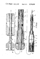
- FIG. 7 is a perspective view of a complete catheter assembly
- FIG. 8 is a cross-sectional view of part of the assembly shown in FIG. 7;
- FIG. 9 is a composite cross-sectional view of the entire assembly shown in FIG. 7.
- the principal components of the illustrated catheter assembly are a primary catheter tube 10 and an everting tube 12, these being the components which actually enter the vascular system of a patient and the assembly being completed by ancilliary equipment remaining external to the patient's body and including an extension tube 14, a manifold 16, syringes 18 and 20 for applying pressure fluid respectively to the outer annulus of the everting tube and to its internal passageway, and a pressure gauge 22 for measuring the pressure of the former fluid.
- the primary catheter tube 10 with the everting tube 12 fully contracted therewithin is inserted into the vascular system and worked along a blood vessel in the conventional manner. Then, when the leading end of the tube 10 has reached its limit of travel through the blood vessel, tube 12 is everted from within tube 10 for further advancement of the catheter along the vessel.
- Tube 10 is a conventional form of flexible catheter tubing used for intra-vascular applications for example, a polyurethane tube of 2.15 mm. outside diameter, 1.4 mm. inside diameter and 1 meter long, the tube having its inner surface treated with a friction reducing hydromer coating.
- the leading end of tube 10 is tapered (FIG. 9) and the forward end of everting tube 12 is fused or welded to the outer surface of tube 10 at the leading end along with a protective cap 24.
- the trailing end of tube 10 is bonded to the extension tube 14, conveniently also of polyurethane and having an outside diameter of 3.8 mm., an inside diameter of 3.12 mm. and a length of 0.6 meters.
- Everting tube 12 is likewise extruded in polyurethane and has, for example, an outside diameter of 1 mm., a wall thickness of 1/15 mm. and a length of 1.6 meters.
- This tube has its outer surface covered with a friction reducing hydromer coating, and after extrusion, is heat set to provide an indented cross-sectional profile, preferably a substantially U-shaped profile, as shown in FIGS. 2 and 3, although other indented profiles such as a cruciform profile are also considered suitable.
- Heat setting of tube 12 may, for example, be effected by winding the tube around a helically grooved or ridged heated drum, whereby the ridge in the drum provides the required indentation in tube 12.
- the forward end of tube 12 is opened out, turned back on itself and welded or fused to the leading end of tube 10 at point 10a under protective cap 24, while the main body of tube 12, the uneverted length or inner wall, is taken back through tube 10 and its rear end is bonded around the opening at the forward end of an axially moveable plastic support tube 26.
- This forward end of tube 26 is also tapered and provided with a slit section 28 formed from one or more slits which serves as a valve arrangement for preventing tube 12 from being pushed back through tube 28.
- the flaps so created by the slit or slits are inwardly deflected by the pressure in the annulus thus producing an obstruction to rearward motion of the secondary tube.
- tube 26 is provided with caps 30 and 32 serving to prevent tube 12 from working back along the space between tubes 14 and 26.
- the rear end of support tube 26 is attached to a sliding metal coupling arrangement 34, to the rear of which is welded a steel tube 36 which extends back through the manifold 16 and carries a connection 38 for the syringe 20.
- Extension tube 14 is at its rear end attached to a metal coupling 40 connected to the manifold and the manifold has passages 42 and 44 connected respectively to syringe 18, via a tap 46, and pressure gauge 22. Syringe 18, thus, communicates via passage 42, coupling 40 and extension tube 14 with the interior of primary catheter tube 10, i.e., with the annular space surrounding the inner wall of the everting tube 12.
- tube 10 With the everting tube 12 and steel tube 36 in the fully retracted condition, tube 10 is introduced into the vascular system at a suitable entry point and worked through a blood vessel in the conventional manner under fluoroscopic observation until it is advanced to its full length or until an obstruction is encountered or until friction impedes its further advance. Then, steel tube 36 is advanced slightly to provide slack in the everting tube. Pressure at about 1.7 to 2 atmospheres is applied to the annular space surrounding the inner wall of tube 12 through syringe 18, causing eversion of tube 12 from the leading end of tube 10 until the slack in tube 12 is taken up, this process again being performed under fluoroscopic observation.
- the fluid used for everting tube 12 is conveniently a standard X-ray contrast media which allows the outline of tube 12 to be viewed under X-ray.
- Tube 12 thus extends from the leading end of tube 10, and when the slack in tube 12 is taken up, the steel tube 36 is further advanced and the process is repeated. This procedure is continued until the everting tube has reached its maximum extension, or until the target region of the blood vessel has been reached.
- the everting tube can be used to transport any object through the blood vessel for diagnostic or other purposes e.g., a catheter guide wire or a small fluid sampling tube.
- the catheter can be withdrawn by releasing pressure from both syringes, retracting steel tube 36, so that tube 12 is itself again retracted into tube 10 and then withdrawing tube 10 from the blood vessel in the normal way.
- a catheter assembly as herein described and its method of application is suitable for use in effecting entry to relatively inaccessibly regions of the vascular system for either therapeutic or diagnostic purposes.
- tube 12 may be provided with sections of differing diameter and in use, the apparatus can be manipulated in such a way that a diameter suited to expand a particular region of the vessel is available for use at the required location and the tube 12 being expansible under elevated pressure for this purpose.
Abstract
Description
Claims (20)
Priority Applications (1)
| Application Number | Priority Date | Filing Date | Title |
|---|---|---|---|
| US06/530,067 US4530698A (en) | 1979-03-19 | 1983-11-02 | Method and apparatus for traversing blood vessels |
Applications Claiming Priority (2)
| Application Number | Priority Date | Filing Date | Title |
|---|---|---|---|
| US06/022,219 US4437857A (en) | 1979-03-19 | 1979-03-19 | Method and apparatus for traversing blood vessels |
| US06/530,067 US4530698A (en) | 1979-03-19 | 1983-11-02 | Method and apparatus for traversing blood vessels |
Related Parent Applications (1)
| Application Number | Title | Priority Date | Filing Date |
|---|---|---|---|
| US06/022,219 Division US4437857A (en) | 1979-03-19 | 1979-03-19 | Method and apparatus for traversing blood vessels |
Publications (1)
| Publication Number | Publication Date |
|---|---|
| US4530698A true US4530698A (en) | 1985-07-23 |
Family
ID=26695688
Family Applications (1)
| Application Number | Title | Priority Date | Filing Date |
|---|---|---|---|
| US06/530,067 Expired - Lifetime US4530698A (en) | 1979-03-19 | 1983-11-02 | Method and apparatus for traversing blood vessels |
Country Status (1)
| Country | Link |
|---|---|
| US (1) | US4530698A (en) |
Cited By (55)
| Publication number | Priority date | Publication date | Assignee | Title |
|---|---|---|---|---|
| US4606347A (en) * | 1983-03-25 | 1986-08-19 | Thomas J. Fogarty | Inverted balloon catheter having sealed through lumen |
| US4946440A (en) * | 1988-10-05 | 1990-08-07 | Hall John E | Evertible membrane catheter and method of use |
| US5171305A (en) * | 1991-10-17 | 1992-12-15 | Imagyn Medical, Inc. | Linear eversion catheter with reinforced inner body extension |
| US5236423A (en) * | 1988-12-13 | 1993-08-17 | Endomed Corporation | Facilitating endoscopy |
| US5346498A (en) * | 1991-11-06 | 1994-09-13 | Imagyn Medical, Inc. | Controller for manipulation of instruments within a catheter |
| US5364345A (en) * | 1991-10-18 | 1994-11-15 | Imagyn Medical, Inc. | Method of tubal recanalization and catheter system therefor |
| US5374247A (en) * | 1991-10-18 | 1994-12-20 | Imagyn Medical, Inc. | Method of delivering a substance to a fallopian tube |
| US5389100A (en) * | 1991-11-06 | 1995-02-14 | Imagyn Medical, Inc. | Controller for manipulation of instruments within a catheter |
| US5472419A (en) * | 1994-01-31 | 1995-12-05 | Imagyn Medical, Inc. | Catheter and method for depositing reproductive material into the reproductive tract of a female |
| WO1998003120A1 (en) | 1996-07-22 | 1998-01-29 | Applied Medical Resources Corporation | Access device with expandable containment member |
| US5971938A (en) * | 1996-04-02 | 1999-10-26 | Hart; Charles C. | Access device with expandable containment member |
| US5993427A (en) * | 1996-12-03 | 1999-11-30 | Laborie Medical Technologies Corp. | Everting tube structure |
| US6004341A (en) * | 1996-12-05 | 1999-12-21 | Loma Linda University Medical Center | Vascular wound closure device |
| US6039721A (en) * | 1996-07-24 | 2000-03-21 | Cordis Corporation | Method and catheter system for delivering medication with an everting balloon catheter |
| US6113579A (en) * | 1998-03-04 | 2000-09-05 | Scimed Life Systems, Inc. | Catheter tip designs and methods for improved stent crossing |
| US6287322B1 (en) | 1995-12-07 | 2001-09-11 | Loma Linda University Medical Center | Tissue opening locator and everter and method |
| US6425901B1 (en) | 1995-12-07 | 2002-07-30 | Loma Linda University Medical Center | Vascular wound closure system |
| US6517515B1 (en) | 1998-03-04 | 2003-02-11 | Scimed Life Systems, Inc. | Catheter having variable size guide wire lumen |
| US6517477B1 (en) | 2000-01-27 | 2003-02-11 | Scimed Life Systems, Inc. | Catheter introducer system for exploration of body cavities |
| US6524326B1 (en) | 1995-12-07 | 2003-02-25 | Loma Linda University Medical Center | Tissue opening locator and everter and method |
| US20030105508A1 (en) * | 2000-03-21 | 2003-06-05 | Johnson Kirk L. | Everting balloon stent delivery system having tapered leading edge |
| US20030168068A1 (en) * | 2000-09-05 | 2003-09-11 | Poole Anthony George | Body cavity liner |
| US20040010216A1 (en) * | 2000-02-24 | 2004-01-15 | Zhu Yong Hua | Device for closing tissue openings |
| US20040054346A1 (en) * | 2000-08-02 | 2004-03-18 | Zhu Yong Hua | Vascular wound closure device and method |
| US20040143272A1 (en) * | 2003-01-17 | 2004-07-22 | Cully Edward H. | Deployment system for an endoluminal device |
| US20040143219A1 (en) * | 2001-06-28 | 2004-07-22 | Gil-Whan Lee | Apparatus for inserting guide wire for use in a catheter |
| US20040143175A1 (en) * | 2000-01-27 | 2004-07-22 | Biosense Webster, Inc. | Bidirectional catheter having mapping assembly |
| US20040143315A1 (en) * | 2003-01-17 | 2004-07-22 | Bruun Steven R. | Deployment system for an endoluminal device |
| US20050036059A1 (en) * | 2003-08-13 | 2005-02-17 | Benad Goldwasser | Ingestible imaging system |
| US20050038318A1 (en) * | 2003-08-13 | 2005-02-17 | Benad Goldwasser | Gastrointestinal tool over guidewire |
| US20050038335A1 (en) * | 2003-08-13 | 2005-02-17 | Yosef Gross | Pressure-propelled system for body lumen |
| US20050090748A1 (en) * | 2001-01-17 | 2005-04-28 | Transvascular, Inc. | Methods and apparatus for acute or chronic delivery of substances or apparatus to extravascular treatment sites |
| US20050095275A1 (en) * | 2003-09-05 | 2005-05-05 | Zhu Yong H. | Dressing delivery system for internal wounds |
| US6890342B2 (en) | 2000-08-02 | 2005-05-10 | Loma Linda University | Method and apparatus for closing vascular puncture using hemostatic material |
| US20050154278A1 (en) * | 2003-12-30 | 2005-07-14 | Oz Cabiri | Gastrointestinal system with traction member |
| US20050154355A1 (en) * | 2004-01-09 | 2005-07-14 | G.I. View Ltd. | Pressure-propelled system for body lumen |
| US20050187570A1 (en) * | 2004-02-19 | 2005-08-25 | Applied Medical Resources Corporation | Embolectomy capture sheath |
| US20050197531A1 (en) * | 2004-01-09 | 2005-09-08 | G.I. View Ltd. | Pressure-propelled system for body lumen |
| US20060058866A1 (en) * | 2003-01-17 | 2006-03-16 | Cully Edward H | Deployment system for an expandable device |
| US20060173440A1 (en) * | 2001-01-17 | 2006-08-03 | Medtronic Vascular, Inc. | Microcatheter Devices and Methods for Targeted Substance Delivery |
| US20060201351A1 (en) * | 2001-07-02 | 2006-09-14 | Gi View Ltd. | Self-propelled imaging system |
| US7172552B2 (en) | 2000-01-27 | 2007-02-06 | Boston Scientific Scimed, Inc. | Catheter introducer system for exploration of body cavities |
| US20070244359A1 (en) * | 2005-08-01 | 2007-10-18 | G.I View Ltd. | Capsule for use in small intestine |
| US20080097292A1 (en) * | 2004-01-09 | 2008-04-24 | Gi Veiw Ltd. | Pressure-Propelled System For Body Lumen |
| US20080161645A1 (en) * | 2005-02-10 | 2008-07-03 | G.I. View Ltd. | Advancement Techniques For Gastrointestinal Tool With Guiding Element |
| US20080167524A1 (en) * | 2003-08-13 | 2008-07-10 | G.I View Ltd. | Gastrointestinal Tool Over Guiding Element |
| US20090182197A1 (en) * | 2005-08-01 | 2009-07-16 | G.I. View Ltd. | Tools for use in small intestine |
| US20110092765A1 (en) * | 2005-08-01 | 2011-04-21 | G.I. View Ltd. | Tools for use in esophagus |
| US20110160536A1 (en) * | 2008-07-30 | 2011-06-30 | Yoram Blum | System and method for enhanced maneuverability |
| US8012167B2 (en) | 2003-08-14 | 2011-09-06 | Loma Linda University Medical Center | Vascular wound closure device and method |
| US8419678B2 (en) | 2004-01-09 | 2013-04-16 | G.I. View Ltd. | Pressure-propelled system for body lumen |
| US8496580B2 (en) | 2004-05-14 | 2013-07-30 | G.I. View Ltd. | Omnidirectional and forward-looking imaging device |
| US8702620B2 (en) | 2008-11-03 | 2014-04-22 | G.I. View Ltd. | Remote pressure sensing system and method thereof |
| US10646688B2 (en) | 2012-02-27 | 2020-05-12 | Hollister Incorporated | Catheter assembly having protective sleeve tip |
| US11364019B1 (en) | 2013-03-14 | 2022-06-21 | William R. Krause | Catheter for lower lung fluid sampling |
Citations (11)
| Publication number | Priority date | Publication date | Assignee | Title |
|---|---|---|---|---|
| US3168092A (en) * | 1961-06-15 | 1965-02-02 | Silverman Daniel | Medical probing instrument having flexible, extrudable tubing adapted to be extraverted under pressure into a body cavity |
| US3433215A (en) * | 1965-10-20 | 1969-03-18 | Daniel Silverman | Apparatus for placing in and retrieving a tubular probe from a body conduit |
| US3433214A (en) * | 1965-10-20 | 1969-03-18 | Daniel Silverman | Method and apparatus for everting under pressure a tubular probe into a body cavity |
| US3502069A (en) * | 1965-10-20 | 1970-03-24 | Daniel Silverman | Method and apparatus for placing in and retrieving a tubular probe from a body cavity |
| US3525329A (en) * | 1965-06-16 | 1970-08-25 | Prime Minister S Office Of The | Evertable,extendible probe |
| DE2406823A1 (en) * | 1974-02-13 | 1975-08-14 | Peter Udo | Catheterisation of straight or sinuous tubular body organs - using double tube, with inner tube continuously turned inside out |
| US3911927A (en) * | 1974-04-17 | 1975-10-14 | Princeton Biomedix | Eversible catheter |
| US3934576A (en) * | 1972-11-17 | 1976-01-27 | Ab Sundsvalls Specialprodukter | Central venous catheter system |
| US4077610A (en) * | 1976-01-06 | 1978-03-07 | Senichi Masuda | Method and apparatus for passing an article through an interior of a pipe |
| US4182342A (en) * | 1978-04-28 | 1980-01-08 | Med-Pro, Ltd. | Naso-gastric feeding device and method of inserting same |
| US4243040A (en) * | 1979-09-17 | 1981-01-06 | Beecher William H | Extracting device for removing objects from human body passages |
-
1983
- 1983-11-02 US US06/530,067 patent/US4530698A/en not_active Expired - Lifetime
Patent Citations (11)
| Publication number | Priority date | Publication date | Assignee | Title |
|---|---|---|---|---|
| US3168092A (en) * | 1961-06-15 | 1965-02-02 | Silverman Daniel | Medical probing instrument having flexible, extrudable tubing adapted to be extraverted under pressure into a body cavity |
| US3525329A (en) * | 1965-06-16 | 1970-08-25 | Prime Minister S Office Of The | Evertable,extendible probe |
| US3433215A (en) * | 1965-10-20 | 1969-03-18 | Daniel Silverman | Apparatus for placing in and retrieving a tubular probe from a body conduit |
| US3433214A (en) * | 1965-10-20 | 1969-03-18 | Daniel Silverman | Method and apparatus for everting under pressure a tubular probe into a body cavity |
| US3502069A (en) * | 1965-10-20 | 1970-03-24 | Daniel Silverman | Method and apparatus for placing in and retrieving a tubular probe from a body cavity |
| US3934576A (en) * | 1972-11-17 | 1976-01-27 | Ab Sundsvalls Specialprodukter | Central venous catheter system |
| DE2406823A1 (en) * | 1974-02-13 | 1975-08-14 | Peter Udo | Catheterisation of straight or sinuous tubular body organs - using double tube, with inner tube continuously turned inside out |
| US3911927A (en) * | 1974-04-17 | 1975-10-14 | Princeton Biomedix | Eversible catheter |
| US4077610A (en) * | 1976-01-06 | 1978-03-07 | Senichi Masuda | Method and apparatus for passing an article through an interior of a pipe |
| US4182342A (en) * | 1978-04-28 | 1980-01-08 | Med-Pro, Ltd. | Naso-gastric feeding device and method of inserting same |
| US4243040A (en) * | 1979-09-17 | 1981-01-06 | Beecher William H | Extracting device for removing objects from human body passages |
Cited By (101)
| Publication number | Priority date | Publication date | Assignee | Title |
|---|---|---|---|---|
| US4606347A (en) * | 1983-03-25 | 1986-08-19 | Thomas J. Fogarty | Inverted balloon catheter having sealed through lumen |
| US4946440A (en) * | 1988-10-05 | 1990-08-07 | Hall John E | Evertible membrane catheter and method of use |
| US5236423A (en) * | 1988-12-13 | 1993-08-17 | Endomed Corporation | Facilitating endoscopy |
| US5171305A (en) * | 1991-10-17 | 1992-12-15 | Imagyn Medical, Inc. | Linear eversion catheter with reinforced inner body extension |
| US5364345A (en) * | 1991-10-18 | 1994-11-15 | Imagyn Medical, Inc. | Method of tubal recanalization and catheter system therefor |
| US5374247A (en) * | 1991-10-18 | 1994-12-20 | Imagyn Medical, Inc. | Method of delivering a substance to a fallopian tube |
| US5346498A (en) * | 1991-11-06 | 1994-09-13 | Imagyn Medical, Inc. | Controller for manipulation of instruments within a catheter |
| US5389100A (en) * | 1991-11-06 | 1995-02-14 | Imagyn Medical, Inc. | Controller for manipulation of instruments within a catheter |
| US5472419A (en) * | 1994-01-31 | 1995-12-05 | Imagyn Medical, Inc. | Catheter and method for depositing reproductive material into the reproductive tract of a female |
| US6524326B1 (en) | 1995-12-07 | 2003-02-25 | Loma Linda University Medical Center | Tissue opening locator and everter and method |
| US6287322B1 (en) | 1995-12-07 | 2001-09-11 | Loma Linda University Medical Center | Tissue opening locator and everter and method |
| US6425901B1 (en) | 1995-12-07 | 2002-07-30 | Loma Linda University Medical Center | Vascular wound closure system |
| US6964675B2 (en) | 1995-12-07 | 2005-11-15 | Loma Linda University Medical Center | Tissue opening locator and everter and method |
| US5971938A (en) * | 1996-04-02 | 1999-10-26 | Hart; Charles C. | Access device with expandable containment member |
| WO1998003120A1 (en) | 1996-07-22 | 1998-01-29 | Applied Medical Resources Corporation | Access device with expandable containment member |
| US5846251A (en) * | 1996-07-22 | 1998-12-08 | Hart; Charles C. | Access device with expandable containment member |
| US6039721A (en) * | 1996-07-24 | 2000-03-21 | Cordis Corporation | Method and catheter system for delivering medication with an everting balloon catheter |
| US5993427A (en) * | 1996-12-03 | 1999-11-30 | Laborie Medical Technologies Corp. | Everting tube structure |
| US6004341A (en) * | 1996-12-05 | 1999-12-21 | Loma Linda University Medical Center | Vascular wound closure device |
| US6517515B1 (en) | 1998-03-04 | 2003-02-11 | Scimed Life Systems, Inc. | Catheter having variable size guide wire lumen |
| US6113579A (en) * | 1998-03-04 | 2000-09-05 | Scimed Life Systems, Inc. | Catheter tip designs and methods for improved stent crossing |
| US7699771B2 (en) | 2000-01-27 | 2010-04-20 | Boston Scientific Scimed, Inc. | Catheter introducer system for exploration of body cavities |
| US8747301B2 (en) | 2000-01-27 | 2014-06-10 | Boston Scientific Scimed, Inc. | Catheter introducer system for exploration of body cavities |
| US20060287577A1 (en) * | 2000-01-27 | 2006-12-21 | Wendlandt Jeffrey M | Catheter introducer system for exploration of body cavities |
| US20100210906A1 (en) * | 2000-01-27 | 2010-08-19 | Boston Scientific Scimed Inc. | Catheter introducer system for exploration of body cavities |
| US20030060680A1 (en) * | 2000-01-27 | 2003-03-27 | Wendlandt Jeffrey Michael | Catheter introducer system for exploration of body cavities |
| US8602973B2 (en) | 2000-01-27 | 2013-12-10 | Boston Scientific Scimed, Inc. | Catheter introducer system for exploration of body cavities |
| US7172552B2 (en) | 2000-01-27 | 2007-02-06 | Boston Scientific Scimed, Inc. | Catheter introducer system for exploration of body cavities |
| US20040143175A1 (en) * | 2000-01-27 | 2004-07-22 | Biosense Webster, Inc. | Bidirectional catheter having mapping assembly |
| US7066880B2 (en) | 2000-01-27 | 2006-06-27 | Boston Scientific Scimed, Inc. | Catheter introducer system for exploration of body cavities |
| US20070118015A1 (en) * | 2000-01-27 | 2007-05-24 | Wendlandt Jeffrey M | Catheter introducer system for exploration of body cavities |
| US20100016665A1 (en) * | 2000-01-27 | 2010-01-21 | Boston Scientific Scimed, Inc. | Catheter introducer system for exploration of body cavities |
| US6517477B1 (en) | 2000-01-27 | 2003-02-11 | Scimed Life Systems, Inc. | Catheter introducer system for exploration of body cavities |
| US20040010216A1 (en) * | 2000-02-24 | 2004-01-15 | Zhu Yong Hua | Device for closing tissue openings |
| US7931628B2 (en) | 2000-02-24 | 2011-04-26 | Loma Linda University Medical Center | Device for closing tissue openings |
| US20030105508A1 (en) * | 2000-03-21 | 2003-06-05 | Johnson Kirk L. | Everting balloon stent delivery system having tapered leading edge |
| US7201770B2 (en) | 2000-03-21 | 2007-04-10 | Cordis Corporation | Everting balloon stent delivery system having tapered leading edge |
| US8491628B2 (en) | 2000-08-01 | 2013-07-23 | Loma Linda University Medical Center | Vascular wound closure device and method |
| US20110046664A1 (en) * | 2000-08-01 | 2011-02-24 | Loma Linda University Medical Center | Vascular wound closure device and method |
| US20040054346A1 (en) * | 2000-08-02 | 2004-03-18 | Zhu Yong Hua | Vascular wound closure device and method |
| US7780699B2 (en) | 2000-08-02 | 2010-08-24 | Loma Linda University Medical Center | Vascular wound closure device and method |
| US20050209637A1 (en) * | 2000-08-02 | 2005-09-22 | Zhu Yong H | Apparatus for closing vascular puncture |
| US8425552B2 (en) | 2000-08-02 | 2013-04-23 | Loma Linda University Medical Center | Apparatus for closing vascular puncture |
| US8702750B2 (en) | 2000-08-02 | 2014-04-22 | Loma Linda University | Apparatus for closing vascular puncture |
| US9320505B2 (en) | 2000-08-02 | 2016-04-26 | Loma Linda University | Apparatus for closing vascular puncture |
| US6890342B2 (en) | 2000-08-02 | 2005-05-10 | Loma Linda University | Method and apparatus for closing vascular puncture using hemostatic material |
| US9101731B2 (en) | 2000-08-02 | 2015-08-11 | Loma Linda University Medical Center | Vascular wound closure device and method |
| US20030168068A1 (en) * | 2000-09-05 | 2003-09-11 | Poole Anthony George | Body cavity liner |
| US20060173440A1 (en) * | 2001-01-17 | 2006-08-03 | Medtronic Vascular, Inc. | Microcatheter Devices and Methods for Targeted Substance Delivery |
| US20100016836A1 (en) * | 2001-01-17 | 2010-01-21 | Medtronic Vascular, Inc. | Methods and Apparatus for Acute or Chronic Delivery or Substances or Apparatus to Extravascular Treatment Sites |
| US7606615B2 (en) * | 2001-01-17 | 2009-10-20 | Medtronic Vascular, Inc. | Methods and apparatus for acute or chronic delivery of substances or apparatus to extravascular treatment sites |
| US8090430B2 (en) | 2001-01-17 | 2012-01-03 | Medtronic Vascular, Inc. | Methods and apparatus for acute or chronic delivery or substances or apparatus to extravascular treatment sites |
| US20050090748A1 (en) * | 2001-01-17 | 2005-04-28 | Transvascular, Inc. | Methods and apparatus for acute or chronic delivery of substances or apparatus to extravascular treatment sites |
| US20040143219A1 (en) * | 2001-06-28 | 2004-07-22 | Gil-Whan Lee | Apparatus for inserting guide wire for use in a catheter |
| US20060201351A1 (en) * | 2001-07-02 | 2006-09-14 | Gi View Ltd. | Self-propelled imaging system |
| US9662237B2 (en) | 2003-01-17 | 2017-05-30 | W. L. Gore & Associates, Inc. | Deployment system for an endoluminal device |
| US20040143272A1 (en) * | 2003-01-17 | 2004-07-22 | Cully Edward H. | Deployment system for an endoluminal device |
| US20070093886A1 (en) * | 2003-01-17 | 2007-04-26 | Cully Edward H | Deployment system for an endoluminal device |
| US20060058866A1 (en) * | 2003-01-17 | 2006-03-16 | Cully Edward H | Deployment system for an expandable device |
| US20040143315A1 (en) * | 2003-01-17 | 2004-07-22 | Bruun Steven R. | Deployment system for an endoluminal device |
| US7556641B2 (en) | 2003-01-17 | 2009-07-07 | Gore Enterprise Holdings, Inc. | Deployment system for an expandable device |
| US20050033402A1 (en) * | 2003-01-17 | 2005-02-10 | Cully Edward H. | Deployment system for an expandable device |
| US7198636B2 (en) | 2003-01-17 | 2007-04-03 | Gore Enterprise Holdings, Inc. | Deployment system for an endoluminal device |
| US11103373B2 (en) | 2003-01-17 | 2021-08-31 | W. L. Gore & Associates, Inc. | Deployment system for an endoluminal device |
| US7753945B2 (en) | 2003-01-17 | 2010-07-13 | Gore Enterprise Holdings, Inc. | Deployment system for an endoluminal device |
| US8602974B2 (en) | 2003-08-13 | 2013-12-10 | G.I. View Ltd. | Gastrointestinal tool over guiding element |
| US20080167524A1 (en) * | 2003-08-13 | 2008-07-10 | G.I View Ltd. | Gastrointestinal Tool Over Guiding Element |
| US20050038318A1 (en) * | 2003-08-13 | 2005-02-17 | Benad Goldwasser | Gastrointestinal tool over guidewire |
| US20050038335A1 (en) * | 2003-08-13 | 2005-02-17 | Yosef Gross | Pressure-propelled system for body lumen |
| US20050036059A1 (en) * | 2003-08-13 | 2005-02-17 | Benad Goldwasser | Ingestible imaging system |
| US7833176B2 (en) | 2003-08-13 | 2010-11-16 | G. I. View Ltd. | Pressure-propelled system for body lumen |
| US8012167B2 (en) | 2003-08-14 | 2011-09-06 | Loma Linda University Medical Center | Vascular wound closure device and method |
| US9364205B2 (en) | 2003-08-14 | 2016-06-14 | Loma Linda University Medical Center | Wound closure device and method |
| US8187627B2 (en) | 2003-09-05 | 2012-05-29 | Loma Linda University Medical Center | Dressing delivery system for internal wounds |
| US20050095275A1 (en) * | 2003-09-05 | 2005-05-05 | Zhu Yong H. | Dressing delivery system for internal wounds |
| US20050154278A1 (en) * | 2003-12-30 | 2005-07-14 | Oz Cabiri | Gastrointestinal system with traction member |
| US7087011B2 (en) | 2003-12-30 | 2006-08-08 | Gi View Ltd. | Gastrointestinal system with traction member |
| US7635345B2 (en) | 2004-01-09 | 2009-12-22 | G. I. View Ltd. | Pressure-propelled system for body lumen |
| US20050154355A1 (en) * | 2004-01-09 | 2005-07-14 | G.I. View Ltd. | Pressure-propelled system for body lumen |
| US7947013B2 (en) | 2004-01-09 | 2011-05-24 | G.I. View Ltd. | Pressure-propelled system for body lumen |
| US8419678B2 (en) | 2004-01-09 | 2013-04-16 | G.I. View Ltd. | Pressure-propelled system for body lumen |
| US7635346B2 (en) | 2004-01-09 | 2009-12-22 | G. I. View Ltd. | Pressure-propelled system for body lumen |
| US20050197531A1 (en) * | 2004-01-09 | 2005-09-08 | G.I. View Ltd. | Pressure-propelled system for body lumen |
| US20080097292A1 (en) * | 2004-01-09 | 2008-04-24 | Gi Veiw Ltd. | Pressure-Propelled System For Body Lumen |
| EP1987787A1 (en) | 2004-02-19 | 2008-11-05 | Applied Medical Resources Corporation | Embolectomy capture sheath |
| WO2005079678A1 (en) | 2004-02-19 | 2005-09-01 | Applied Medical Resources Corporation | Embolectomy capture sheath |
| US20050187570A1 (en) * | 2004-02-19 | 2005-08-25 | Applied Medical Resources Corporation | Embolectomy capture sheath |
| US8496580B2 (en) | 2004-05-14 | 2013-07-30 | G.I. View Ltd. | Omnidirectional and forward-looking imaging device |
| US20080161645A1 (en) * | 2005-02-10 | 2008-07-03 | G.I. View Ltd. | Advancement Techniques For Gastrointestinal Tool With Guiding Element |
| US10080481B2 (en) | 2005-02-10 | 2018-09-25 | G.I. View Ltd. | Advancement techniques for gastrointestinal tool with guiding element |
| US20110092765A1 (en) * | 2005-08-01 | 2011-04-21 | G.I. View Ltd. | Tools for use in esophagus |
| US9241614B2 (en) | 2005-08-01 | 2016-01-26 | G.I. View Ltd. | Tools for use in esophagus |
| US20070244359A1 (en) * | 2005-08-01 | 2007-10-18 | G.I View Ltd. | Capsule for use in small intestine |
| US8430809B2 (en) | 2005-08-01 | 2013-04-30 | G. I View Ltd. | Capsule for use in small intestine |
| US20090182197A1 (en) * | 2005-08-01 | 2009-07-16 | G.I. View Ltd. | Tools for use in small intestine |
| US20110160536A1 (en) * | 2008-07-30 | 2011-06-30 | Yoram Blum | System and method for enhanced maneuverability |
| US10226600B2 (en) | 2008-07-30 | 2019-03-12 | G.I. View Ltd. | System and method for enhanced maneuverability |
| US8702620B2 (en) | 2008-11-03 | 2014-04-22 | G.I. View Ltd. | Remote pressure sensing system and method thereof |
| US10646688B2 (en) | 2012-02-27 | 2020-05-12 | Hollister Incorporated | Catheter assembly having protective sleeve tip |
| US11701489B2 (en) | 2012-02-27 | 2023-07-18 | Hollister Incorporated | Catheter assembly having protective sleeve tip |
| US11364019B1 (en) | 2013-03-14 | 2022-06-21 | William R. Krause | Catheter for lower lung fluid sampling |
Similar Documents
| Publication | Publication Date | Title |
|---|---|---|
| US4530698A (en) | Method and apparatus for traversing blood vessels | |
| US4437857A (en) | Method and apparatus for traversing blood vessels | |
| US5749849A (en) | Variable stiffness balloon catheter | |
| US5059176A (en) | Vascular system steerable guidewire with inflatable balloon | |
| US5265622A (en) | Guidewire having radially expandable member and method for guiding and advancing a catheter using the same | |
| US5207229A (en) | Flexibility steerable guidewire with inflatable balloon | |
| JP3349151B2 (en) | Catheter with internal mandrel and method of use | |
| US4762129A (en) | Dilatation catheter | |
| US5706827A (en) | Magnetic lumen catheter | |
| US4983167A (en) | Balloon catheters | |
| US5820592A (en) | Angiographic and/or guide catheter | |
| US5976107A (en) | Catheter having extendable guide wire lumen | |
| CA2138805C (en) | Dilatation catheter with injection lumen | |
| US5263931A (en) | Balloon catheter for dilating a prostatic urethra | |
| US5090958A (en) | Balloon catheters | |
| US5713854A (en) | Method and apparatus for dilatation catheterization | |
| US5019042A (en) | Balloon catheters | |
| US5232445A (en) | Dilatation catheter | |
| US5514108A (en) | Soft flexible catheter tip for use in angiography | |
| EP0416734A1 (en) | Guide catheter and guidewires for effecting rapid catheter exchange | |
| EP0657140A1 (en) | Catheter system for forming a passage through an arterial blockage prior to atherectomy or angioplasty | |
| EP0227583A2 (en) | Pressurized manual advancement dilatation catheter | |
| CN110799236A (en) | Vascular anchoring introducer sheath | |
| EP0359489A2 (en) | Everting balloon catheter with anchor annulus and balloon for same | |
| WO1984001903A1 (en) | Double lumen dilatation catheter |
Legal Events
| Date | Code | Title | Description |
|---|---|---|---|
| STCF | Information on status: patent grant |
Free format text: PATENTED CASE |
|
| FEPP | Fee payment procedure |
Free format text: PAYOR NUMBER ASSIGNED (ORIGINAL EVENT CODE: ASPN); ENTITY STATUS OF PATENT OWNER: LARGE ENTITY |
|
| CC | Certificate of correction | ||
| FPAY | Fee payment |
Year of fee payment: 4 |
|
| FEPP | Fee payment procedure |
Free format text: PAYER NUMBER DE-ASSIGNED (ORIGINAL EVENT CODE: RMPN); ENTITY STATUS OF PATENT OWNER: LARGE ENTITY Free format text: PAYOR NUMBER ASSIGNED (ORIGINAL EVENT CODE: ASPN); ENTITY STATUS OF PATENT OWNER: LARGE ENTITY |
|
| FPAY | Fee payment |
Year of fee payment: 8 |
|
| FEPP | Fee payment procedure |
Free format text: PAYOR NUMBER ASSIGNED (ORIGINAL EVENT CODE: ASPN); ENTITY STATUS OF PATENT OWNER: LARGE ENTITY Free format text: PAYER NUMBER DE-ASSIGNED (ORIGINAL EVENT CODE: RMPN); ENTITY STATUS OF PATENT OWNER: LARGE ENTITY |
|
| FEPP | Fee payment procedure |
Free format text: PAYER NUMBER DE-ASSIGNED (ORIGINAL EVENT CODE: RMPN); ENTITY STATUS OF PATENT OWNER: LARGE ENTITY Free format text: PAYOR NUMBER ASSIGNED (ORIGINAL EVENT CODE: ASPN); ENTITY STATUS OF PATENT OWNER: LARGE ENTITY |
|
| REMI | Maintenance fee reminder mailed | ||
| FPAY | Fee payment |
Year of fee payment: 12 |
|
| SULP | Surcharge for late payment |