US4544927A - Wideband beamformer - Google Patents

Wideband beamformer Download PDF

Info

Publication number
US4544927A
US4544927A US06/439,258 US43925882A US4544927A US 4544927 A US4544927 A US 4544927A US 43925882 A US43925882 A US 43925882A US 4544927 A US4544927 A US 4544927A
Authority
US
United States
Prior art keywords
sector
beams
phase
signals
shift
Prior art date
Legal status (The legal status is an assumption and is not a legal conclusion. Google has not performed a legal analysis and makes no representation as to the accuracy of the status listed.)
Expired - Fee Related
Application number
US06/439,258
Inventor
Richard R. Kurth
Robert A. Gabel
Current Assignee (The listed assignees may be inaccurate. Google has not performed a legal analysis and makes no representation or warranty as to the accuracy of the list.)
Sperry Corp
Original Assignee
Sperry Corp
Priority date (The priority date is an assumption and is not a legal conclusion. Google has not performed a legal analysis and makes no representation as to the accuracy of the date listed.)
Filing date
Publication date
Application filed by Sperry Corp filed Critical Sperry Corp
Priority to US06/439,258 priority Critical patent/US4544927A/en
Assigned to SPERRY CORPORATION A DE CORP reassignment SPERRY CORPORATION A DE CORP ASSIGNMENT OF ASSIGNORS INTEREST. Assignors: GABEL, ROBERT A., KURTH, RICHARD R.
Application granted granted Critical
Publication of US4544927A publication Critical patent/US4544927A/en
Anticipated expiration legal-status Critical
Expired - Fee Related legal-status Critical Current

Links

Images

Classifications

    • GPHYSICS
    • G10MUSICAL INSTRUMENTS; ACOUSTICS
    • G10KSOUND-PRODUCING DEVICES; METHODS OR DEVICES FOR PROTECTING AGAINST, OR FOR DAMPING, NOISE OR OTHER ACOUSTIC WAVES IN GENERAL; ACOUSTICS NOT OTHERWISE PROVIDED FOR
    • G10K11/00Methods or devices for transmitting, conducting or directing sound in general; Methods or devices for protecting against, or for damping, noise or other acoustic waves in general
    • G10K11/18Methods or devices for transmitting, conducting or directing sound
    • G10K11/26Sound-focusing or directing, e.g. scanning
    • G10K11/34Sound-focusing or directing, e.g. scanning using electrical steering of transducer arrays, e.g. beam steering
    • G10K11/341Circuits therefor
    • G10K11/346Circuits therefor using phase variation
    • HELECTRICITY
    • H01ELECTRIC ELEMENTS
    • H01QANTENNAS, i.e. RADIO AERIALS
    • H01Q3/00Arrangements for changing or varying the orientation or the shape of the directional pattern of the waves radiated from an antenna or antenna system
    • H01Q3/26Arrangements for changing or varying the orientation or the shape of the directional pattern of the waves radiated from an antenna or antenna system varying the relative phase or relative amplitude of energisation between two or more active radiating elements; varying the distribution of energy across a radiating aperture

Landscapes

  • Physics & Mathematics (AREA)
  • Engineering & Computer Science (AREA)
  • Acoustics & Sound (AREA)
  • Multimedia (AREA)
  • Measurement Of Velocity Or Position Using Acoustic Or Ultrasonic Waves (AREA)
  • Variable-Direction Aerials And Aerial Arrays (AREA)

Abstract

A beamformer that accommodates signals of substantially wider bandwith than conventional phase-shift beamformers by processing signals coupled from an array of sensor elements in a multi-stage sequence of operations that alternate between phase-shift beamforming and time-delay steering.

Description

BACKGROUND OF THE INVENTION
1. Field of the Invention
The present invention relates to beamforming by receiving signals with sensors in an array, and more particularly to beamforming with such arrays when wideband signals are received.
2. Description of the Prior Art
Sonar, radar, communications, seismological prospecting, and tomography systems employ arrays of spatially distributed sensors which sample physical quantities such as pressure or electromagnetic fields and convert these quantities to electrical signals. These electrical signals are processed to produce a second set of signals that enhance wave arrivals from selected directions, while discriminating against wave arrivals from other directions, thereby forming beams in the selected directions. This process is known in the art as beamforming and the network to which the sensors are coupled is known as a beamforming network. Signals from the sensor coupled to the beamforming network may be continuous or sampled analog waveforms or they may be sampled and digitized to establish digital signals. Beamforming with analog signals requires that each signal be time delayed in accordance with the desired beam direction and the position of the receiving sensor in the array, amplitude weighted in accordance with the beam shape desired, and added with the other signals to form a beam output signal. These time delays, weightings, and sum operations are generally duplicated for each selected beam direction. When the signals received by the sensors are at frequencies within a narrow band centered about a carrier frequency f0, the required delay operations may be performed by lumped constant phase-shift circuits that provide phase shifts in accordance with φ=2πf0 τk, where τk is a function of the selected direction and k is an integer index corresponding to the receiving sensor.
Sensor output signals may be directly sampled or may first be hetrodyned to a convenient intermediate frequency and then sampled. Alternatively, a pair of signals may be derived which represent the in-phase and quadrature signal components relative to the carrier frequency f0, each such signal being sampled. The signal sample pairs thus produced may be considered a complex-valued signal sample Sk (nΔt), derived from the kth array element, where n is the time sample index and Δt the sample period. For receptions which are narrowband about the carrier frequency f0, these time-sampled signals are phase-shifted and summed to form a beam in accordance with ##EQU1## where Bm (nΔt) is the mth beam output signal, Sk (nΔt) is the sampled signal from the kth sensor, ak is the weighting or shading factor for the signal from the kth sensor, and φkm the phase-shift value required to phase-align the signal from the kth sensor with the signals from all the other sensors for the mth beam selection direction. It is well known that the sampling rate (Δt)-1 must exceed the bandwidth W of the sensor output signal about the carrier frequency.
Signal samples produced by a uniform plane wave at the carrier frequency, arriving at an angle θ, at the kth element of an array of K sensors linearly positioned with uniform spacing of d wavelengths at the center frequency f0 may be represented as Sk (nΔt)=Ae-j2πkd sin θ where A is the wave amplitude. If the sensor signals are subjected to phase shifts φkm =(2πkm)/K applied thereto and then summed, m being a constant that may take on the values 0, 1, 2, . . . , (K-1), the array will be steered to couple signals from the sensors for summations that are of equal phase for plane wave fronts at the carrier frequency arriving at angles defined by θm =sin-1 (m/Kd). With this phase gradient the sum of the sample signals Bm (nΔt) becomes ##EQU2## which is well known in the art as the discrete Fourier tranform (DFT). When the frequency band of the signals Sk received at the sensors is sufficiently broad about the carrier frequency, beam steering as described above fails to operate properly since the phase shift values at the elements, though based on the propagation delays of the wave front as it crosses the array, do not provide proper phase shifts for signal components at frequencies sufficiently far removed from the carrier.
Consider steering a uniform colinear array to a direction θm =sin-1 (m/Kd) for a wave at the carrier frequency f0. The phase shifts required for the kth sensor in the beamforming process are thus ##EQU3## where λ=c/f0 is the wavelength at the carrier frequency and c is the wave propagation speed. When the wave arriving from θm has a temporal frequency f0 +Δf, it induces a relative phase shift at the kth sensor of ##EQU4## and the phase shifter at each element no longer exactly compensates for the propagation-induced phase shift. In fact a beam for a selected angle θm under the assumption of the frequency f0, is steered to the angle ##EQU5## for an incident wave at frequency f0 +Δf. This defocusing effect causes the response of the phase-shift beamformer to encompass a broader spatial angle, provides a diminished beam amplitude, and causes adjacent beams to smear together, resulting in a loss of directional resolution. Thus the maximum scan angle of a phase-shift steered array is a function of the array size and the operating signal bandwidth W, the maximum scan angle being given approximately by ##EQU6## where Ta is the time required for a wave traveling parallel to the array elements to traverse the array and Ta W is a fill-time/bandwidth product for the array.
The fill-time/bandwidth product scan angle limitation has been overcome in the prior art with sampled data versions of delay and sum beamforming. In one method sensor signals are sampled at a rate much faster than that required by the signal bandwidth, and beams are formed by selecting sensor samples corresponding to the required sensor delays for the desired beam angle of arrival. Another method utilized in the prior art, as described by R. G. Pridham and R. A. Mucci, "A Novel Approach to Digital Beamforming", Journal of the Acoustical Society of America, volume 63, pp. 425-434, February 1978, performs sampling at a rate that is slower than the above mentioned sampling rate to form estimates of the sensor signal samples at the desired delays via interpolation. Though these beamforming methods exhibit satisfactory performance with wideband signals, they are considerably more complex and expensive to build than phase-shift beamformers.
SUMMARY OF THE INVENTION
The present invention relates to a beamformer coupled to an array of sensor elements for operation with a signal bandwidth that exceeds the band limits, for the overall length of the array and maximum scan angle, over which conventional phase-shift beamforming may be employed. The beamformer includes a first beamforming stage that comprises a multiplicity of conventional phase-shift beamformers each coupled to contiguous elements of the array to form a multiplicity of subarrays. Sector beams are formed for each of these subarrays in the first beamforming stage, such that sector beam directions are scanned in parallel through a plurality of sectors within the overall scanning range of the system. Each sector beam output signal from the first stage phase-shift beamformers is coupled to a time delay stage wherein signals are time delayed by interpolation in accordance with the subarray position in the overall array and the sector scan angle to establish delay alignment at the respective subarray output terminals of the time delay interpolator for each sector beam steering direction. The signals at the output terminals of the time delay interpolator are then coupled to a third stage comprising a conventional phase-shift beamformer which forms beams at selected scan angles within each sector beam.
This technique may be utilized to construct beamformers having more than three stages (e.g. five, seven, etc.), alternating between time-delay alignment and phase-shift steering after the third stage of the beamformer. This arrangement establishes sub-sectors scanned within each sector and sub-sub-sectors scanned within each sub-sector. The total number of sub-divisions of the angular space is dependent upon the number of time-delay/phase-shift combination sections added after the third stage.
BRIEF DESCRIPTION OF THE DRAWINGS
FIG. 1 is a block diagram of a beamformer having a multiplicity of sensor elements and a plurality of beam output terminals.
FIG. 2 is a block diagram of a preferred embodiment of the invention.
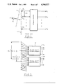
FIG. 3 is a block diagram of a sensor element array coupled to a plurality of conventional phase-shift beamformers forming a first stage of the preferred embodiment of the invention.
FIG. 4 is a block diagram of a discrete Fourier transform beamformer having a greater number of sensor elements coupled thereto than there are input terminals thereof and a generally lesser number of beam output terminals than input terminals.
FIG. 5 is an illustration of the sector beams available from the beamformer of FIG. 4.
FIG. 6 is a diagram useful in the explanation of the time delay applied to each sector beam output.
FIG. 7 is a block diagram of a time-delay interpolation circuit.
FIGS. 8 and 9 are graphs that are useful for explaining the interpolation coefficients shown in FIG. 7.
FIGS. 10, 11, and 12 are illustrations useful for describing sector information and beamformation within a sector.
FIG. 13 is a block diagram of a preferred embodiment of the invention employing more than three stages.
DESCRIPTION OF THE PREFERRED EMBODIMENTS
In FIG. 1 is illustrated a beamformer of the prior art wherein an array of sensor elements E1 through EK are colinearly positioned with the uniform spacings dλ, where λ is the wavelength at the band center or carrier frequency f0. Though these beamformers are generally employed for arrays with uniform spacing, non-uniform spacing with elements positioned on a uniform grid, but not all the grid positions being filled by an element, have also been utilized in the prior art. Directional responses of the elements in the array are usually identical and may generally be factored from the overall beamformer directional response. In determining this overall beamformer directional response each sensor element may be considered to yield a complex-valued time-sampled signal sequence Sk (nΔt) for the kth sensor, such signals having frequency components within the range ±W/2 arising from frequency components in the receptions within the range f0 ±W/2, and sampled at a frequency 1/Δt which is W plus an anti-aliasing margin. The scanning range of these arrays is limited by the inverse fill-time/bandwidth factor (WTa)-1 where Ta =Kdλ/c, c being the propagation velocity of the signal in the array environment.
A plane wave with temporal frequency f0 +Δf having a uniform phase front 11 arriving at an angle θ with respect to the normal 12 to the plane 13 of the array of elements E1 through EK induces a signal at each element that may be represented as:
S.sub.k =Ae.sup.-j2πdksinθλ(f.sbsp.0 +Δf)/c
where A is the amplitude of the plane wave. In the beamformer an amplitude factor ak and a phase shift (2πkm)/K are applied to each of the element signals, the resulting signals then being summed to form M beams (M≦K) such that a signal for the mth beam appears at an output terminal, the sum at that output terminal being ##EQU7##
The beamformer of the present invention comprises a multiplicity of stages, as for example the three stages shown in FIG. 2. The first stage 14 may be divided into N phase-shift beamformers, each coupled to a subarray of Ks elements with subarray centers uniformly spaced by Ld wavelengths, i.e. by L-element spacings as shown in FIG. 3. The number of elements Ks in each subarray may exceed the number of element L spacing of the subarray centers, whereby the subarrays will overlap and share some elements. Consequently the full array is comprised of K=(N-1) L+Ks elements uniformly spaced by dλ. The elements of each subarray are coupled to beamformers 141 through 14N, each of which may be of the discrete Fourier transform type well known in the art, wherein identical phase-shift beamforming is performed on the Ks signals from the elements comprising each subarray to produce a set of Ns (Ns ≦Ks) subarray output beams for each subarray steered in directions corresponding to Ns sectors, which collectively span the entire field of view of interest, with the peak direction of corresponding sector beams of each subarray being in a parallel relationship. It will be recognized that the maximum scanning angle of these parallel beams is limited in substantial accordance with
| sin θ.sub.N.sbsb.s |≦f.sub.0 /K.sub.s dW
However, this limitation is dependent upon the subarray aperture of Ks d wavelengths so that the latter may be selected to provide a set of sector beams spanning the entire field of view of interest without violating the limitation over the operating bandwidth W.
The second stage 15 in the beamformer subjects the subarray beam output signals to time delays that provide proper time alignment of the subarray beams for each sector steering direction.
After the subarray beam output signals for each sector are suitably delayed in the second stage of the beamformer, each of the so delayed N subarray beam output signals may be phase-shift steered in a beamformer of the discrete Fourier transform type in a third stage 16 to produce Ms full-resolution beams within each directional sector, thus providing a total of M=Ns Ms beam signals at the output terminals of the beamformer. Each of the M beams thus produced has a directional resolution that is determined by the overall array aperture. Each beam has a nominal width in sin θ space of 1/Kd with beam separations of 1/Kd. Such beam coverage is normally associated with exclusive phase-shift beamforming. Thus, the composite beamformer provides the coverage of a phase shift beamformer over a significantly wider signal band.
All the subarray phase-shift beamformers 141 through 14N in the first stage are to steer beams, with main lobe directional responses that each cover a sector, to provide the overall angular coverage desired. Consequently each subarray aperture in wavelengths (Ks d) must be substantially equal to the inverse of sin θs, where θs is the sector beam width. When the beamformers 141 through 14N are of the DFT type the signal at the kth element in each subarray is phase-shifted by 2πmk/N1, where m is the sector beam index and N1 is the number of input terminals to the DFT beamformer (N1 point DFT). If more than N1 equally spaced elements are employed in the array, as for example E'-2 through E'N.sbsb.1+1 elements shown in FIG. 4, the phase difference to be induced between the elements j and j+N1 is substantially 2πm. Consequently the signal phases to be induced between elements separated by N1 element positions are substantially equal, thus permitting the paired addition of these signals in summation circuits C0, C1, CN.sbsb.1-2, and CN.sbsb.1-1, as shown in FIG. 4 after the application of the weighting factors to the signals by amplifiers A-2 through AN.sbsb.1 +1 and prior to coupling to an appropriate input port of phase-shift beamformer 14J. Thus, the Ks elements of each subarray form uniformly spaced sector beams that establish signals at the output terminals of the beamformer in accordance with ##EQU8## where the summation is performed over index valves corresponding to all elements in the subarray. The peak sector beam response occurs at an angle Ψm that is determined from sin Ψm=m /N1 d.
Representative directional responses for an eight point DFT beamformer for which Ks is greater than N1 =8, and for which weighting factors have been choosen for beam broadening, are shown in FIG. 5. In sin θ space the beam separation is 1/N1 d, while each beam exhibits a nominal transition width of 1/Ks d. Though eight representative beams are shown, not all need be utilized and the number of sector beams Ns may be fewer than the number of steering angles N1 available. Not shown in the figure are any grating lobes at multiples of 1/d which may be associated with the subarray patterns. It is well known that array parameters may be selected to avoid subarray sector beam grating lobes in directions from which wave arrivals may be expected. Consistent with FIG. 4, wherein Ks exceeds N1, the transition width of each beam in FIG. 5 is shown to be less than the beam spacing. If, however, Ks =N1 the transition widths and the peak spacings would be substantially equal.
Subarray beamforming as discussed above may be implemented with arithmetic, logic, and memory devices when the simultaneously sampled sensor element signals are digitzed by one or more analog to digital (A/D) converters. The DFT has a highly regular structure which may be exploited in the construction of hardware This hardware is fully described in the literature and may be found in "Theory and Application of Digital Signal Processing" by Rabiner and Gold published by Prentice Hall, Inc., Englewood Cliffs, N.J. Particularly efficient circuit architectures are known for special values of the DFT parameter N1, e.g., when it is a power of two or a product of prime numbers. Alternatively, when the sensor signals are sampled but not digitized, circuits such as charge-transfer devices may be employed to accomplish the DFT, or when the signals are not sampled, the well-known Butler Matrix may be utilized to efficiently implement the phase-shift beamforming process.
Referring again to FIG. 2, the output signals from the Ns sector beams at the output terminals of PSB 141 are coupled via lines 1711 through 171N.sbsb.s to time-delay circuits 151 through 15N.sbsb.s, while the output signals from the Ns sector beams at the output terminals of PSB 142 through 14N are respectively coupled to time-delay circuits 151 through 15N.sbsb.s via lines 1721 through 172N.sbsb.s and 17N1 through 17N Ns respectively. In these time-delay circuits 151 through 15N.sbsb.s subarray beam output signals for each of N sets of parallel beams, for example the subarray beam output signals coupled via lines 1711 through 17N.sbsb.1, are time-delayed to compensate for wave front arrival delays according to the sector steering angles Ψm =sin-1 (m /N1 d).
Referring to FIG. 6, wherein the centers 181 through 18N of each of the subarrays SA1 through SAN of FIG. 2 are shown, the relative time delay to be applied to the output signal for the mth sector beam of the kth subarray is thus ##EQU9## where Ψm is the sector beam angle relative to the normal 21 to the array surface 22, Xmk is the wavefront displacement distance and τo is an arbitrary time offset applied to the output signals of all subarrays for the sector beam under consideration. These time delays may be provided by interpolating the subarray sector beam output signals to the time instants specified above and repeating such interpolation in each successive sampling period. In FIG. 7 a block diagram of a circuit for performing this interpolation is shown. The sector beam output signal D(nΔt) is coupled to input terminal 23 wherefrom samples are coupled to a tapped delay line 24, which may be a shift register, tapped at intervals of Δt. Each of the delayed samples in the delay line may be coupled respectively to amplifiers 250 through 25Q, having gains that may be programmed by via leads 260 through 26Q in accordance with the desired interpolation delay, to provide the proper weighting factors for a postulated delay functionality. These weighted samples are coupled to summation network 27 wherefrom an output signal D(nΔt) representative of the delayed input D(nΔt) is provided. The time-delay interpolation as discussed above may be implemented with arithmetic, logic, and memory devices which perform the weighted sum of delayed subarray sector beam output samples as shown in FIG. 7. This circuitry may be arranged in the form of a digital filter. Alternatively, analog sampled-data filters such as those utilizing charge-transfer or switched-capacitor devices may be employed for the delay interpolation.
Referring now to FIG. 8, assume that an interpolation for time τmk =(n-q-1)Δt+τ is desired and that the functionality is as shown by the dotted curve 31. The weighting coefficients βk realized by the amplifier gains in FIG. 7 are selected so that the output of the delay interpolation network approximates D(τmk), the functionality at the desired delay. For example, if two samples of sector beam output are combined by linear interpolation for a desired delay of τmk =(n-1).sup.Δt +τ as shown in FIG. 9, then
B.sub.o (τ.sub.mk)=τ/Δt=α
B.sub.1 (τ.sub.mk)=1-τ/Δt=1-α
D(nΔt)=αD(nΔt)+(1-α) D[(n-1)Δt]
The principles of designing delay interpolation networks are well-known, for example as discussed in "A Comparison of Equiripple FIR and IIR Interpolators", by R. A. Gabel, Proceedings of the 1981 Asilomar Conference on Circuits, Systems, and Computers, November 1981, pp. 55-59.
Referring again to FIG. 2, each set of delayed subarray beam outputs for each sector are coupled from time delay circuits 151 through 15N.sbsb.s to phase-shift beamformers 191 through 19N.sbsb.s respectively, e.g. time delayed signals are coupled from the time delay circuit 151 via lines 1811 through 18N.sbsb.1 to the phase-shift beamformer 191. Each set of N delayed subarray output signals Dk may be applied to a N2 -point DFT to form N2 beams within each sector in accordance with ##EQU10## where l is the index for the output beams in that sector and the bk are coefficients which shape the third stage beam patterns and include the factors exp(j2πKLd sin Ψm). The latter provide subarray center carrier phase shift compensation of the delayed sector beam signals DK (nΔt) for the sector beam steering angle Ψm. Since the spacing of the subarrays is Ldλ, the DFT phase-shift beamformers 191 through 19N.sbsb.s each provide signals at the outputs thereof representative of N2 beams within a sector that are pointed in directions relative to each sector steering direction in sin θ space that are determined from ##EQU11## From the N2 output beam signals thereby produced in each sector, Ms (Ms ≦N2) of these beam signals are coupled to the respective output terminals in FIG. 2, e.g. Yl (nΔt) for the first sector to B1 through BM.sbsb.s. The field of view in sin θ space covered by the Ms final output beams in each sector should not exceed the scan angle limitation f0 /KdW.
In FIG. 10 a sector beam directional response 37 is shown along with additional sector responses spaced by 1/N1 d, while in FIG. 11 a set of patterns 38 for the N2 possible beams produced by the DFT of the third stage phase-shift beamformer is shown. Since the subarray phase centers are separated by Ldλ, each third stage beamformer pattern exhibits grating lobes typified by 39A and 39B at multiples of 1/Ld in sin θ space, falling, however, outside of the sector response 37. Ms of the N2 available third stage DFT output signals for each sector are selected about the center of the sector as final output beams in that sector, as illustrated in FIG. 12. This operation is repeated in all sectors to establish an ensemble of M=Ns Ms full-resolution output beams that uniformly span the directional space coordinate sin θ. It should be apparent to one skilled in the art that the Ms beams in a sector formed by the third stage will continuously span the entire space when N2 L=N1 Ms. The subarray size, element spacing, weighting coefficients, and first stage DFT parameters should be selected to be compatible with this principle of operation.
The invention has been described in terms of a beamformer constructed of three stages comprising a subarray sector beamsteering phase-shift network, a subarray sector beam output delay-alignment network, and a subsector phase-shift beamforming network. By decomposing the array into several orders of generally overlapping subarrays and the beam angle space into several orders of sectors, beamformers of this type may be constructed having more than three (e.g., 5, 7, 9, etc.) stages, alternating between phase-shift steering and time-delay alignment. For example, as shown in FIG. 13, the Ns Ms output ports of a multiplicity of third stage beamformers 42A through 42P may be coupled to a second set of time delay circuits 43, forming a fourth stage of the system. Corresponding beam ports from the beamformer sets 42A through 42P are coupled to a common time delay unit; as for example, the first beam ports B1A through B1P of each beamformer set 42A through 42P are coupled to inputs of the first time delay unit of 43, and the last beam ports BM.sbsb.sN.sbsb.sA (BMA) through BM.sbsb.sN.sbsb.sP (BMP) of each beamformer set 42A through 42P are coupled to inputs of the last time delay unit of 43. The output ports 44 of each time delay unit may then be coupled to a plurality of phase shift beamformers, forming a fifth stage, to provide the desired beams at the output ports 46 of the beamformers, as previously described.
It will be noted by those skilled in the art that the principles of the invention above described may be applied to construct a beamformer for a two-dimensional array of sensors lying in a common plane and located on a regular grid, e.g., a rectangular grid with uniform spacings in each dimension, which may be different for each dimension. In this case the first beamforming stage phase-shift steers signals from identical subarrays to a set of sector steering directions. The planar array is thereby decomposed into generally overlapping, geometrically regular (e.g. rectangular) subarrays. The first stage phase-shift steering is to a set of sector directions uniformly spaced in the two-directional coordinates, so that it may be accomplished by efficient implementation of two-dimensional Fourier transform operations. Subarray sector beams are then properly time-aligned by interpolation according to sector steering directions and the subarray phase-center locations. The third stage in the beamformer is sub-sector phase-shift steering of the two-dimensional set of subarray beams in each sector. Two-dimensional Fourier transform operations may also be employed to perform this function. The beamformer operating principles may be extended to regularly spaced three-dimensional arrays in a similar fashion.
It will be recognized by those skilled in the art that the invention as described may utilize reciprocal elements and as such may be employed as a receiving or a transmitting beamformer.
While the invention has been described in its preferred embodiments, it is to be understood that the words which have been used are words of description rather than limitation and changes may be made within the purview of the appended claims without departing from the true scope and spirit of the invention in its broader aspects.

Claims (5)

We claim:
1. A wideband beamformer comprising:
first beamforming means having means for coupling to an array of sensor elements for forming sets of sector beams numbering N, each set having a number NS of sector beams, equal for all sets, each sector beam covering an angular sector, thereby providing a total of NNS sector beams, said sector beams of said sets being in a one-to-one correspondence with corresponding sector beams covering like angular sectors and said sector beams of each set in totality spanning an angular region and for providing signals representative of said sector beams at output terminals, said output terminals being in one-to-one correspondence with said NNS sector beams for providing time delays to said sector beam representative signals for time aligning representative signals of corresponding sector beams; and
second beamforming means having input terminals coupled to receive said time aligned sector beam representative signals for providing phase-shifts to said time aligned sector beam representative signals to form sub-sector beams, numbering MS, within and angularly spanning each sector beam, thereby providing MS NS sub-sector beams.
2. A wideband beamformer in accordance with claim 1 wherein:
said coupling to said array of sensor elements provides a plurality of subarrays numbering N and correspondingly associated with said sets of sector beams;
said first beamforming means includes beamformers of a number equal to said plurality of subarrays each of said beamformers coupled to one subarray to provide said sector beams within said angular region.
3. A wideband beamformer in accordance with claim 2 wherein said beamformers of said first beamforming means are of the discrete Fourier transform type.
4. A wideband beamformer in accordance with claim 2 wherein each of said time delay circuits includes means for providing time delay by interpolation.
5. A method for forming a beam, which comprises:
positioning a plurality of sensor elements to form sensor element array;
forming a multiplicity of subarrays, all having substantially equal angular coverage, from said sensor element array;
coupling each subarray to a corresponding one of a multiplicity of angular sector phase-shift beamformers, said angular sector phase-shift beamformers having a plurality of output terminals, of equal number for all angular sector phase-shift beamformers, with corresponding output terminals being related to an angular sector within said angular region;
coupling corresponding output terminals to time-delay circuits to time align signals from corresponding output terminals;
coupling said time delay circuits to a subsector phase-shift beamformer having output terminals for phase-shifting said time aligned signals to form a plurality of subsector beams within said angular sector and provide signals representative of each of said subsector beams at a corresponding one of said output terminals.
US06/439,258 1982-11-04 1982-11-04 Wideband beamformer Expired - Fee Related US4544927A (en)

Priority Applications (1)

Application Number Priority Date Filing Date Title
US06/439,258 US4544927A (en) 1982-11-04 1982-11-04 Wideband beamformer

Applications Claiming Priority (1)

Application Number Priority Date Filing Date Title
US06/439,258 US4544927A (en) 1982-11-04 1982-11-04 Wideband beamformer

Publications (1)

Publication Number Publication Date
US4544927A true US4544927A (en) 1985-10-01

Family

ID=23743973

Family Applications (1)

Application Number Title Priority Date Filing Date
US06/439,258 Expired - Fee Related US4544927A (en) 1982-11-04 1982-11-04 Wideband beamformer

Country Status (1)

Country Link
US (1) US4544927A (en)

Cited By (46)

* Cited by examiner, † Cited by third party
Publication number Priority date Publication date Assignee Title
US4675682A (en) * 1984-10-18 1987-06-23 The United States Of America As Represented By The Secretary Of The Air Force Magnetostatic delay line with improved delay linearity
US4743914A (en) * 1986-04-14 1988-05-10 Raytheon Company Space fed antenna system with squint error correction
US4864311A (en) * 1984-03-24 1989-09-05 The General Electric Company, P.L.C. Beam forming network
FR2638573A1 (en) * 1988-11-03 1990-05-04 Alcatel Espace ELECTRONIC SCAN ANTENNA
EP0381498A2 (en) * 1989-02-03 1990-08-08 Matsushita Electric Industrial Co., Ltd. Array microphone
US5041836A (en) * 1990-06-14 1991-08-20 Ball Corporation Self-steered antenna system
US5059966A (en) * 1989-02-10 1991-10-22 Mitsubishi Denki Kabushiki Kaisha Synthetic aperture radar system
US5093668A (en) * 1989-06-29 1992-03-03 Ball Corporation Multiple-beam array antenna
US5132694A (en) * 1989-06-29 1992-07-21 Ball Corporation Multiple-beam array antenna
US5461389A (en) * 1991-12-19 1995-10-24 The Secretary Of State For Defence In Her Britannic Majesty's Government Of The United Kingdom Of Great Britain And Northern Island Digital beamforming array
US5479177A (en) * 1984-11-20 1995-12-26 Ail Systems Inc. Phased array antenna system to produce wide-open coverage of a wide angular sector with high directive gain and wide frequency bandwidth
US5680371A (en) * 1995-07-31 1997-10-21 Arete Engineering Technologies Corporation Broadband sonar method and apparatus for use with conventional sonar arrays
US5771439A (en) * 1996-05-20 1998-06-23 Raytheon E-Systems, Inc. Adaptive antenna system and method for cellular and personal communication systems
WO1998034294A2 (en) * 1997-02-03 1998-08-06 Teratech Corporation Multi-dimensional beamforming device
US5884192A (en) * 1994-06-03 1999-03-16 Telefonaktiebolaget Lm Ericsson Diversity combining for antennas
EP1103950A2 (en) * 1999-11-24 2001-05-30 Her Majesty The Queen In Right Of Canada As Represented By The Minister Of National Defence High resolution 3D ultrasound imaging system deploying a multi-dimensional array of sensors and method for multi-dimensional beamforming sensor signals
US6292433B1 (en) 1997-02-03 2001-09-18 Teratech Corporation Multi-dimensional beamforming device
US6445647B1 (en) * 1999-08-24 2002-09-03 The United States Of America As Represented By The Secretary Of The Navy Wideband-to-narrowband conversion method and apparatus
US20040047463A1 (en) * 2002-09-09 2004-03-11 Samsung Electronics Co., Ltd. Robust symbol timing recovery circuit for telephone line modem
US6721235B2 (en) 1997-02-03 2004-04-13 Teratech Corporation Steerable beamforming system
US6768456B1 (en) 1992-09-11 2004-07-27 Ball Aerospace & Technologies Corp. Electronically agile dual beam antenna system
WO2004083885A2 (en) * 2003-03-21 2004-09-30 Qinetiq Limited Time delaybeamformer and method of time delay beamforming
WO2004107812A1 (en) 2003-06-02 2004-12-09 Yamaha Corporation Array speaker system
US20040252802A1 (en) * 2003-06-13 2004-12-16 Fujitsu Limited Data transmission device and input/output interface circuit
US6842401B2 (en) 2000-04-06 2005-01-11 Teratech Corporation Sonar beamforming system
US20050101867A1 (en) * 2003-10-28 2005-05-12 Johnson Jeremy A. Apparatus and method for phased subarray imaging
US20080303711A1 (en) * 2007-06-11 2008-12-11 Mitsubishi Electric Corporation Radar apparatus
US8259005B1 (en) * 2009-03-18 2012-09-04 Lockheed Martin Corporation True time delay diversity beamforming
JP2014064114A (en) * 2012-09-20 2014-04-10 Japan Radio Co Ltd Receiving array antenna device
US9184498B2 (en) 2013-03-15 2015-11-10 Gigoptix, Inc. Extending beamforming capability of a coupled voltage controlled oscillator (VCO) array during local oscillator (LO) signal generation through fine control of a tunable frequency of a tank circuit of a VCO thereof
US9275690B2 (en) 2012-05-30 2016-03-01 Tahoe Rf Semiconductor, Inc. Power management in an electronic system through reducing energy usage of a battery and/or controlling an output power of an amplifier thereof
US9509351B2 (en) 2012-07-27 2016-11-29 Tahoe Rf Semiconductor, Inc. Simultaneous accommodation of a low power signal and an interfering signal in a radio frequency (RF) receiver
US9531070B2 (en) 2013-03-15 2016-12-27 Christopher T. Schiller Extending beamforming capability of a coupled voltage controlled oscillator (VCO) array during local oscillator (LO) signal generation through accommodating differential coupling between VCOs thereof
US9666942B2 (en) 2013-03-15 2017-05-30 Gigpeak, Inc. Adaptive transmit array for beam-steering
US9716315B2 (en) 2013-03-15 2017-07-25 Gigpeak, Inc. Automatic high-resolution adaptive beam-steering
US9722310B2 (en) 2013-03-15 2017-08-01 Gigpeak, Inc. Extending beamforming capability of a coupled voltage controlled oscillator (VCO) array during local oscillator (LO) signal generation through frequency multiplication
US9780449B2 (en) 2013-03-15 2017-10-03 Integrated Device Technology, Inc. Phase shift based improved reference input frequency signal injection into a coupled voltage controlled oscillator (VCO) array during local oscillator (LO) signal generation to reduce a phase-steering requirement during beamforming
US9837714B2 (en) 2013-03-15 2017-12-05 Integrated Device Technology, Inc. Extending beamforming capability of a coupled voltage controlled oscillator (VCO) array during local oscillator (LO) signal generation through a circular configuration thereof
US20190049572A1 (en) * 2017-08-14 2019-02-14 Oculii Corp Systems and methods for doppler-enhanced radar tracking
US10819306B2 (en) * 2018-10-24 2020-10-27 Thinkom Solutions, Inc. Lossless lobing circuit for multi-subarray tracking
US11041940B1 (en) 2019-12-20 2021-06-22 Oculii Corp. Systems and methods for phase-modulated radar detection
US11047974B1 (en) 2019-12-13 2021-06-29 Oculii Corp. Systems and methods for virtual doppler and/or aperture enhancement
US11280879B2 (en) 2020-06-16 2022-03-22 Oculii Corp. System and method for radar interference mitigation
US11561299B1 (en) 2022-06-03 2023-01-24 Oculii Corp. System and method for multi-waveform radar tracking
US11841420B2 (en) 2020-11-16 2023-12-12 Oculii Corp. System and method for radar-based localization and/or mapping
US11860267B2 (en) 2018-01-30 2024-01-02 Ambarella International Lp Systems and methods for interpolated virtual aperture radar tracking

Citations (7)

* Cited by examiner, † Cited by third party
Publication number Priority date Publication date Assignee Title
US3484785A (en) * 1968-05-03 1969-12-16 Raytheon Co Beam-steering apparatus
US3510871A (en) * 1967-07-12 1970-05-05 Mitsubishi Electric Corp Radio detection apparatus
US3763490A (en) * 1971-12-10 1973-10-02 Gen Electric Adaptive beamformer with time constant control
US3840875A (en) * 1973-08-23 1974-10-08 J Neal Radiant energy matrix and system
US4112430A (en) * 1977-06-01 1978-09-05 The United States Of America As Represented By The Secretary Of The Navy Beamformer for wideband signals
US4263600A (en) * 1979-12-10 1981-04-21 Hughes Aircraft Company Wide-band, phase scanned antenna
US4290127A (en) * 1979-12-03 1981-09-15 Raytheon Company Beamformer with reduced sampling rate

Patent Citations (7)

* Cited by examiner, † Cited by third party
Publication number Priority date Publication date Assignee Title
US3510871A (en) * 1967-07-12 1970-05-05 Mitsubishi Electric Corp Radio detection apparatus
US3484785A (en) * 1968-05-03 1969-12-16 Raytheon Co Beam-steering apparatus
US3763490A (en) * 1971-12-10 1973-10-02 Gen Electric Adaptive beamformer with time constant control
US3840875A (en) * 1973-08-23 1974-10-08 J Neal Radiant energy matrix and system
US4112430A (en) * 1977-06-01 1978-09-05 The United States Of America As Represented By The Secretary Of The Navy Beamformer for wideband signals
US4290127A (en) * 1979-12-03 1981-09-15 Raytheon Company Beamformer with reduced sampling rate
US4263600A (en) * 1979-12-10 1981-04-21 Hughes Aircraft Company Wide-band, phase scanned antenna

Non-Patent Citations (12)

* Cited by examiner, † Cited by third party
Title
A. Chottera and G. A. Jullien, "Designing Near Linear Phase Recursive Filters Using Linear Programming," Proc. of 1977 Intl. Conf. on Acoust., Speech, and Signal Proc., Hartford, Conn., pp. 88-92.
A. Chottera and G. A. Jullien, Designing Near Linear Phase Recursive Filters Using Linear Programming, Proc. of 1977 Intl. Conf. on Acoust., Speech, and Signal Proc., Hartford, Conn., pp. 88 92. *
F. J. Brophy and A. C. Salazar, "Two Design Techniques for Digital Phase Networks," Bell Syst. Tech. J., vol. 54, Apr., 1975, pp. 767-781.
F. J. Brophy and A. C. Salazar, Two Design Techniques for Digital Phase Networks, Bell Syst. Tech. J., vol. 54, Apr., 1975, pp. 767 781. *
K. Steiglitz, "Design of FIR Digital Phase Networks," Proceedings of 1980 Intl. Conf. Acoust., Speech, and Signal Proc., Denver, Colorado, pp. 252-255.
K. Steiglitz, Design of FIR Digital Phase Networks, Proceedings of 1980 Intl. Conf. Acoust., Speech, and Signal Proc., Denver, Colorado, pp. 252 255. *
R. A. Gabel, "On Asymmetric FIR Interpolators with Minimum Lp Error," Proceedings of 1980 Intl. Conf. Acoust., Speech, and Signal Proc., Denver, Colorado, pp. 256-259.
R. A. Gabel, "On the Design and Performance of Equiripple IIR Interpolators," Proceedings of 1981 Intl. Conf. Acoust., Speech, and Signal Proc., Atlanta, Georgia, pp. 232-235.
R. A. Gabel, "On the Performance of Equiripple FIR Interpolating Filters," Proc. of Fourteenth Asilomar Conf. on Circuits, Systems, and Computers, Nov. 1980.
R. A. Gabel, On Asymmetric FIR Interpolators with Minimum Lp Error, Proceedings of 1980 Intl. Conf. Acoust., Speech, and Signal Proc., Denver, Colorado, pp. 256 259. *
R. A. Gabel, On the Design and Performance of Equiripple IIR Interpolators, Proceedings of 1981 Intl. Conf. Acoust., Speech, and Signal Proc., Atlanta, Georgia, pp. 232 235. *
R. A. Gabel, On the Performance of Equiripple FIR Interpolating Filters, Proc. of Fourteenth Asilomar Conf. on Circuits, Systems, and Computers, Nov. 1980. *

Cited By (69)

* Cited by examiner, † Cited by third party
Publication number Priority date Publication date Assignee Title
US4864311A (en) * 1984-03-24 1989-09-05 The General Electric Company, P.L.C. Beam forming network
US4675682A (en) * 1984-10-18 1987-06-23 The United States Of America As Represented By The Secretary Of The Air Force Magnetostatic delay line with improved delay linearity
US5479177A (en) * 1984-11-20 1995-12-26 Ail Systems Inc. Phased array antenna system to produce wide-open coverage of a wide angular sector with high directive gain and wide frequency bandwidth
US4743914A (en) * 1986-04-14 1988-05-10 Raytheon Company Space fed antenna system with squint error correction
FR2638573A1 (en) * 1988-11-03 1990-05-04 Alcatel Espace ELECTRONIC SCAN ANTENNA
EP0368121A1 (en) * 1988-11-03 1990-05-16 Alcatel Espace Electronically scanned antenna
US5038147A (en) * 1988-11-03 1991-08-06 Alcatel Espace Electronically scanned antenna
EP0381498A2 (en) * 1989-02-03 1990-08-08 Matsushita Electric Industrial Co., Ltd. Array microphone
EP0381498A3 (en) * 1989-02-03 1991-09-18 Matsushita Electric Industrial Co., Ltd. Array microphone
US5059966A (en) * 1989-02-10 1991-10-22 Mitsubishi Denki Kabushiki Kaisha Synthetic aperture radar system
US5093668A (en) * 1989-06-29 1992-03-03 Ball Corporation Multiple-beam array antenna
US5132694A (en) * 1989-06-29 1992-07-21 Ball Corporation Multiple-beam array antenna
US5041836A (en) * 1990-06-14 1991-08-20 Ball Corporation Self-steered antenna system
US5461389A (en) * 1991-12-19 1995-10-24 The Secretary Of State For Defence In Her Britannic Majesty's Government Of The United Kingdom Of Great Britain And Northern Island Digital beamforming array
US6768456B1 (en) 1992-09-11 2004-07-27 Ball Aerospace & Technologies Corp. Electronically agile dual beam antenna system
US20040263387A1 (en) * 1992-09-11 2004-12-30 Ball Aerospace & Technologies Corp. Electronically agile dual beam antenna system
US20050012655A1 (en) * 1992-09-11 2005-01-20 Ball Corporation Electronically agile multi-beam antenna system
US6771218B1 (en) 1992-09-11 2004-08-03 Ball Aerospace & Technologies Corp. Electronically agile multi-beam antenna
US5884192A (en) * 1994-06-03 1999-03-16 Telefonaktiebolaget Lm Ericsson Diversity combining for antennas
US5680371A (en) * 1995-07-31 1997-10-21 Arete Engineering Technologies Corporation Broadband sonar method and apparatus for use with conventional sonar arrays
US5822276A (en) * 1995-07-31 1998-10-13 Arete Engineering Technologies Corporation Broadband sonar method and apparatus for use with conventional sonar sensor arrays
US5771439A (en) * 1996-05-20 1998-06-23 Raytheon E-Systems, Inc. Adaptive antenna system and method for cellular and personal communication systems
WO1998034294A2 (en) * 1997-02-03 1998-08-06 Teratech Corporation Multi-dimensional beamforming device
US6552964B2 (en) 1997-02-03 2003-04-22 Teratech Corporation Steerable beamforming system
US6671227B2 (en) 1997-02-03 2003-12-30 Teratech Corporation Multidimensional beamforming device
US6721235B2 (en) 1997-02-03 2004-04-13 Teratech Corporation Steerable beamforming system
US6292433B1 (en) 1997-02-03 2001-09-18 Teratech Corporation Multi-dimensional beamforming device
US20050018540A1 (en) * 1997-02-03 2005-01-27 Teratech Corporation Integrated portable ultrasound imaging system
US6111816A (en) * 1997-02-03 2000-08-29 Teratech Corporation Multi-dimensional beamforming device
WO1998034294A3 (en) * 1997-02-03 1998-10-29 Teratech Corp Multi-dimensional beamforming device
US6445647B1 (en) * 1999-08-24 2002-09-03 The United States Of America As Represented By The Secretary Of The Navy Wideband-to-narrowband conversion method and apparatus
EP1103950A3 (en) * 1999-11-24 2006-09-13 Her Majesty The Queen In Right Of Canada As Represented By The Minister Of National Defence High resolution 3D ultrasound imaging system deploying a multi-dimensional array of sensors and method for multi-dimensional beamforming sensor signals
EP1103950A2 (en) * 1999-11-24 2001-05-30 Her Majesty The Queen In Right Of Canada As Represented By The Minister Of National Defence High resolution 3D ultrasound imaging system deploying a multi-dimensional array of sensors and method for multi-dimensional beamforming sensor signals
US6842401B2 (en) 2000-04-06 2005-01-11 Teratech Corporation Sonar beamforming system
US20040047463A1 (en) * 2002-09-09 2004-03-11 Samsung Electronics Co., Ltd. Robust symbol timing recovery circuit for telephone line modem
US7333579B2 (en) * 2002-09-09 2008-02-19 Samsung Electronics Co., Ltd. Robust symbol timing recovery circuit for telephone line modem
US20060220956A1 (en) * 2003-03-21 2006-10-05 Richardson Peter G Time delay beamformer and method of time delay beamforming
WO2004083885A2 (en) * 2003-03-21 2004-09-30 Qinetiq Limited Time delaybeamformer and method of time delay beamforming
WO2004083885A3 (en) * 2003-03-21 2004-12-23 Qinetiq Ltd Time delaybeamformer and method of time delay beamforming
US7737892B2 (en) 2003-03-21 2010-06-15 Qinetiq Limited Time delay beamformer and method of time delay beamforming
WO2004107812A1 (en) 2003-06-02 2004-12-09 Yamaha Corporation Array speaker system
CN1799283B (en) * 2003-06-02 2012-08-29 雅马哈株式会社 Array speaker system
US20040252802A1 (en) * 2003-06-13 2004-12-16 Fujitsu Limited Data transmission device and input/output interface circuit
US7542532B2 (en) * 2003-06-13 2009-06-02 Fujitsu Limited Data transmission device and input/output interface circuit
US20050101867A1 (en) * 2003-10-28 2005-05-12 Johnson Jeremy A. Apparatus and method for phased subarray imaging
US20080303711A1 (en) * 2007-06-11 2008-12-11 Mitsubishi Electric Corporation Radar apparatus
US7579982B2 (en) * 2007-06-11 2009-08-25 Mitsubishi Electric Corporation Radar apparatus
US8259005B1 (en) * 2009-03-18 2012-09-04 Lockheed Martin Corporation True time delay diversity beamforming
US9275690B2 (en) 2012-05-30 2016-03-01 Tahoe Rf Semiconductor, Inc. Power management in an electronic system through reducing energy usage of a battery and/or controlling an output power of an amplifier thereof
US9509351B2 (en) 2012-07-27 2016-11-29 Tahoe Rf Semiconductor, Inc. Simultaneous accommodation of a low power signal and an interfering signal in a radio frequency (RF) receiver
JP2014064114A (en) * 2012-09-20 2014-04-10 Japan Radio Co Ltd Receiving array antenna device
US9184498B2 (en) 2013-03-15 2015-11-10 Gigoptix, Inc. Extending beamforming capability of a coupled voltage controlled oscillator (VCO) array during local oscillator (LO) signal generation through fine control of a tunable frequency of a tank circuit of a VCO thereof
US9531070B2 (en) 2013-03-15 2016-12-27 Christopher T. Schiller Extending beamforming capability of a coupled voltage controlled oscillator (VCO) array during local oscillator (LO) signal generation through accommodating differential coupling between VCOs thereof
US9666942B2 (en) 2013-03-15 2017-05-30 Gigpeak, Inc. Adaptive transmit array for beam-steering
US9716315B2 (en) 2013-03-15 2017-07-25 Gigpeak, Inc. Automatic high-resolution adaptive beam-steering
US9722310B2 (en) 2013-03-15 2017-08-01 Gigpeak, Inc. Extending beamforming capability of a coupled voltage controlled oscillator (VCO) array during local oscillator (LO) signal generation through frequency multiplication
US9780449B2 (en) 2013-03-15 2017-10-03 Integrated Device Technology, Inc. Phase shift based improved reference input frequency signal injection into a coupled voltage controlled oscillator (VCO) array during local oscillator (LO) signal generation to reduce a phase-steering requirement during beamforming
US9837714B2 (en) 2013-03-15 2017-12-05 Integrated Device Technology, Inc. Extending beamforming capability of a coupled voltage controlled oscillator (VCO) array during local oscillator (LO) signal generation through a circular configuration thereof
US10613212B2 (en) * 2017-08-14 2020-04-07 Oculii Corp. Systems and methods for doppler-enhanced radar tracking
US20190049572A1 (en) * 2017-08-14 2019-02-14 Oculii Corp Systems and methods for doppler-enhanced radar tracking
US11237261B2 (en) 2017-08-14 2022-02-01 Oculii Corp. Systems and methods for doppler-enhanced radar tracking
US11946998B2 (en) 2017-08-14 2024-04-02 Oculii Corp. Systems and methods for doppler-enhanced radar tracking
US11860267B2 (en) 2018-01-30 2024-01-02 Ambarella International Lp Systems and methods for interpolated virtual aperture radar tracking
US10819306B2 (en) * 2018-10-24 2020-10-27 Thinkom Solutions, Inc. Lossless lobing circuit for multi-subarray tracking
US11047974B1 (en) 2019-12-13 2021-06-29 Oculii Corp. Systems and methods for virtual doppler and/or aperture enhancement
US11041940B1 (en) 2019-12-20 2021-06-22 Oculii Corp. Systems and methods for phase-modulated radar detection
US11280879B2 (en) 2020-06-16 2022-03-22 Oculii Corp. System and method for radar interference mitigation
US11841420B2 (en) 2020-11-16 2023-12-12 Oculii Corp. System and method for radar-based localization and/or mapping
US11561299B1 (en) 2022-06-03 2023-01-24 Oculii Corp. System and method for multi-waveform radar tracking

Similar Documents

Publication Publication Date Title
US4544927A (en) Wideband beamformer
US4652879A (en) Phased array antenna system to produce wide-open coverage of a wide angular sector with high directive gain and strong capability to resolve multiple signals
US4112430A (en) Beamformer for wideband signals
US9800316B2 (en) Beamforming devices and methods
US5179386A (en) Cylindrical phased array antenna system to produce wide open coverage of a wide angular sector with high directive gain and strong capability to resolve multiple signals
US4254417A (en) Beamformer for arrays with rotational symmetry
US4431995A (en) Phased array signal processing
JP6605744B2 (en) Correlated fan beam forming machine
CA1139376A (en) Charge coupled device
US5479177A (en) Phased array antenna system to produce wide-open coverage of a wide angular sector with high directive gain and wide frequency bandwidth
WO2004083885A2 (en) Time delaybeamformer and method of time delay beamforming
US5430453A (en) Cylindrical phased array antenna system to produce wide-open coverage of a wide angular sector with high directive gain and moderate capability to resolve multiple signals
US5325101A (en) Cylindrical phased array antenna system to prodce wide open coverage of a wide angular sector with high directive gain and wide frequency bandwidth
US4213133A (en) Linear antenna arrays
US5228006A (en) High resolution beam former apparatus
US5410320A (en) Cylindrical phased array antenna system to produce wide open coverage of a wide angular sector with high directive gain
US5596550A (en) Low cost shading for wide sonar beams
JP3068481B2 (en) DBF antenna device
US4654667A (en) Signal-acquisition system for a circular array
US4604626A (en) Acquisition system employing circular array
Gray Effect of time-delay errors on the beam pattern of a linear array
US4413332A (en) Scanning beamformer for a very high resolution circular arc sonar
USH108H (en) Radar doppler processor using a fast orthogonalization network
Walach On superresolution effects in maximum likelihood adaptive antenna arrays
Jahromi et al. Steering broadband beamforming without pre-steering

Legal Events

Date Code Title Description
AS Assignment

Owner name: SPERRY CORPORATION GREAT NECK NJ 11020 A DE CORP

Free format text: ASSIGNMENT OF ASSIGNORS INTEREST.;ASSIGNORS:KURTH, RICHARD R.;GABEL, ROBERT A.;REEL/FRAME:004161/0858

Effective date: 19821029

Owner name: SPERRY CORPORATION A DE CORP,NEW JERSEY

Free format text: ASSIGNMENT OF ASSIGNORS INTEREST;ASSIGNORS:KURTH, RICHARD R.;GABEL, ROBERT A.;REEL/FRAME:004161/0858

Effective date: 19821029

FPAY Fee payment

Year of fee payment: 4

FEPP Fee payment procedure

Free format text: PAYOR NUMBER ASSIGNED (ORIGINAL EVENT CODE: ASPN); ENTITY STATUS OF PATENT OWNER: LARGE ENTITY

FPAY Fee payment

Year of fee payment: 8

REMI Maintenance fee reminder mailed
LAPS Lapse for failure to pay maintenance fees
FP Lapsed due to failure to pay maintenance fee

Effective date: 19971001

STCH Information on status: patent discontinuation

Free format text: PATENT EXPIRED DUE TO NONPAYMENT OF MAINTENANCE FEES UNDER 37 CFR 1.362