US4545375A - Electrosurgical instrument - Google Patents
Electrosurgical instrument Download PDFInfo
- Publication number
- US4545375A US4545375A US06/503,110 US50311083A US4545375A US 4545375 A US4545375 A US 4545375A US 50311083 A US50311083 A US 50311083A US 4545375 A US4545375 A US 4545375A
- Authority
- US
- United States
- Prior art keywords
- switch
- wire
- core member
- contact
- leg
- Prior art date
- Legal status (The legal status is an assumption and is not a legal conclusion. Google has not performed a legal analysis and makes no representation as to the accuracy of the status listed.)
- Expired - Fee Related
Links
Images


Classifications
-
- H—ELECTRICITY
- H01—ELECTRIC ELEMENTS
- H01H—ELECTRIC SWITCHES; RELAYS; SELECTORS; EMERGENCY PROTECTIVE DEVICES
- H01H9/00—Details of switching devices, not covered by groups H01H1/00 - H01H7/00
- H01H9/02—Bases, casings, or covers
- H01H9/06—Casing of switch constituted by a handle serving a purpose other than the actuation of the switch, e.g. by the handle of a vacuum cleaner
-
- A—HUMAN NECESSITIES
- A61—MEDICAL OR VETERINARY SCIENCE; HYGIENE
- A61B—DIAGNOSIS; SURGERY; IDENTIFICATION
- A61B18/00—Surgical instruments, devices or methods for transferring non-mechanical forms of energy to or from the body
- A61B18/04—Surgical instruments, devices or methods for transferring non-mechanical forms of energy to or from the body by heating
- A61B18/12—Surgical instruments, devices or methods for transferring non-mechanical forms of energy to or from the body by heating by passing a current through the tissue to be heated, e.g. high-frequency current
- A61B18/14—Probes or electrodes therefor
- A61B18/1402—Probes for open surgery
-
- A—HUMAN NECESSITIES
- A61—MEDICAL OR VETERINARY SCIENCE; HYGIENE
- A61B—DIAGNOSIS; SURGERY; IDENTIFICATION
- A61B18/00—Surgical instruments, devices or methods for transferring non-mechanical forms of energy to or from the body
- A61B2018/00053—Mechanical features of the instrument of device
- A61B2018/00107—Coatings on the energy applicator
-
- H—ELECTRICITY
- H01—ELECTRIC ELEMENTS
- H01H—ELECTRIC SWITCHES; RELAYS; SELECTORS; EMERGENCY PROTECTIVE DEVICES
- H01H2300/00—Orthogonal indexing scheme relating to electric switches, relays, selectors or emergency protective devices covered by H01H
- H01H2300/014—Application surgical instrument
Definitions
- the present invention relates generally to medical electronic apparatus and electrical switching devices, and more particularly to such a device especially suitable as an electrosurgical switching handpiece.
- a suitable electrical generator provides a high frequency or radio-frequency (RF) signal which is transmitted to a small surgical electrode having a thin knife-like tip to be applied to a patient.
- RF radio-frequency
- the patient sits or lies on a patient plate and is grounded thereto, with the plate being connected by a further conductor back to the generator.
- the relatively extremely small area of contact by the electrode with the patient provides an intense current in a highly localized area, producing a cutting action.
- the current passes through the patient's body to the patient plate where the area of contact is so great that no burning effect occurs to the patient.
- the generator is activated to produce a continuous signal, typically a sinewave signal.
- a continuous signal typically a sinewave signal.
- the same instrument may be used to apply to the wound after cutting in order to produce coagulation.
- the generator may be selectively activated to produce a pulsing signal which produces the desired results.
- Switching means are available for the operator to selectively control an activating means for causing the generator to produce the desired type of current.
- Suitable control switches may be mounted on the instrument panel of the generator to be operated by an assistant. This is generally considered to be unsatisfactory because of the delay involved in transmitting instructions.
- foot operated switches are provided which may be controlled by the surgeon. However, this interferes with his mobility because he must stand in one place or move the foot switches about on the floor.
- U.S. Pat. No. 3,801,766 to Morrison, Jr. discloses a hand-held electrical switching device for an electrosurgical instrument including a rectangularly shaped printed circuit board including three spaced apart electrical contacts.
- a spring contact member is disposed in electrical conducting engagement with the center contact and includes oppositely positioned contacts, each of which is adapted to be selectively engaged to one of the other contacts by means of a hand-activated rocker button.
- the Morrison patent is assigned to Valleylab, and while not described in this present patent, Valleylab markets a similar electrosurgical device which includes a sleeve member which is heat-shrunk over the printed circuit board to seal the circuit board from fluids. Such heat sealing requires the use of special equipment which is costly.
- U.S. Pat. No. 3,911,241 to Jarrard shows an electrosurgical instrument including a switch with a pair of spaced contacts encased in a flexible housing. The space between the contacts allows actuation of the switch by manually squeezing the housing. More than one pair of spaced contacts may be incorporated in the housing.
- This reference discloses the use of a heat-shrinkable flexible covering to establish an environmental seal about the conductive elements.
- U.S. Pat. No. 4,034,761 to Preter shows a hand-held electrosurgical switching assembly in which the switching member is mounted in the electrode handle for selectively moving one of the bowed portions of the resilient conductive member into contact with a wire wrap contact for actuation of the electrode blade in a desired operative mode.
- some commercially available hand-actuated electrosurgical switching instruments utilize a flexible resilient sheath member externally around the housing and positioned to cover the switching buttons in an attempt to seal the switching mechanism from fluids. While this may keep fluids from entering through the cracks surrounding the actuating buttons, it does not prevent fluids from entering the housing via the cracks at the distal end of the instrument where the electrode blade enters the housing, or at the proximal end where the cable exits from the handpiece. Consequently, this means of sealing is generally not very effective.
- a principle object of this invention is to provide a hand-actuated electrosurgical switching instrument which is simple and economical to manufacture and assemble, while at the same time, the unique construction of the instrument insures a highly reliable and precise instrument.
- Another object of the invention is to provide such an instrument which is economically produced from suitable materials, so that it can be disposed after use, thus insuring a new sterile instrument for each operation.
- a further object of the invention is to provide a hand-actuated electrosurgical switching instrument which includes a simple, yet effective means for sealing the switching mechanism from fluids.
- a still further object of the invention is to provide such a sealed electrosurgical instrument which includes a main core portion for the switching mechanism, which may be fully encapsulated by a simple resilient sleeve so that the switching mechanism cannot be inadvertantly activated should the pencil be immersed in or splashed with a conductive fluid.
- An even further object of the invention is to provide an electrosurgical switching mechanism which is simple to assemble.
- the present invention accomplishes all of the above objects of invention.
- the present invention provides a hand-actuated electrosurgical switching instrument which is very simple to manufacture and assemble and yet provides a reliable switching mechanism.
- the instrument includes an insulated elongated inner core molded about an elongated main contact wire.
- the main contact wire extends throughout the length of the core and protrudes from both the distal and proximal ends of the core.
- An electrically conductive terminal connects to the distally protruding end of the main contact wire. This terminal electrically connects and secures a replaceable electrode blade assembly.
- the proximally protruding end of the main contact wire electrically connects to an RF wire which ultimately leads back through an insulated cable and a connector to an electrical generator or power source.
- the inner core preferably includes two separate and selectively operable switch wires mounted thereon.
- the switches are longitudinally spaced apart from each other on the core, and may conveniently and easily snap into cooperating groove in the core. One end of each switch is aligned above and spaced apart from a respective window portion in the core. The window portion exposes a section of the main contact wire so that manual deflection of the switch wire will cause electrical contact with the main contact wire.
- Each switch wire is separately connected by a magnet wire via the insulated cable to the electrical power source. One wire is connected to an electrical signal suitable for cutting of tissue, while the other switch is connected to a different electrical signal suitable for coagulation of tissue.
- the electrosurgical generator supplies a pre-selected current to the electrode blade dependent upon which switch component is activated. Such cutting and coagulation signals are well known in the art and will not be further discussed herein.
- the inner core is easily seated within the external housing of the instrument.
- a convenient selector means is mounted in the housing to provide externally activated deflection of the desired switch wire to provide the desired cutting or coagulation mode.
- the inner core may be sealably encapsulated in a resilient sleeve member so that the switching mechanism cannot be inadvertantly activated, should the instrument be immersed in or splashed with a conductive fluid.
- the selector means is operable through the sleeve to selectively activate the desired switch.
- the sleeve fits tightly over the elongated core in order to prevent such fluid from entering the switching area of the electrosurgical instrument. Additionally, this sealing protects the operator from RF current following the path of the conductive fluid from the internal circuitry to the user's hand.
- the individual components of the present invention are designed to provide a highly dependable switching instrument while permitting simple, quick and economical assembly, so that the electrosurgical hand-actuated switching instrument may economically be provided as a disposable instrument in order to assure a sterile instrument for each operation.
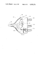
- FIG. 1 is a perspective view of the electrosurgical instrument assembly according to the present invention
- FIG. 2 is a cross-sectional view taken through lines 2--2 of FIG. 1;
- FIG. 3 is an enlarged view of the mid-portion of FIG. 2;
- FIG. 4 is a perspective view of the inner core, including the resilient sealing sleeve member of the electrosurgical instrument of FIG. 2;
- FIG. 5 is a perspective view of the interior of the top half of the housing of the electrosurgical instrument of FIG. 1;
- FIG. 6 is a perspective view of the interior of the bottom half of the housing of the electrosurgical instrument of FIG. 1;
- FIG. 7 is a top plan view of a selector button of the electrosurgical instrument of FIG. 1;
- FIG. 8 is a perspective view of a switch wire of the electrosurgical instrument of FIG. 2;
- FIG. 9 is a perspective view of the sleeve member of the electrosurgical instrument of FIG. 2;
- FIG. 10 is a top view of the core of the electrosurgical instrument of FIG. 2;
- FIG. 11a is a side view of the core of FIG. 10;
- FIG. 11b is an end view of the distal end of the core of FIG. 11a;
- FIG. 11c is an end view of the proximal end of the core of FIG. 11a;
- FIG. 12 is a bottom view of the core of FIG. 10;
- FIG. 13 is a cross-sectional view of the core of FIG. 10 taken along lines 13--13;
- FIG. 14 is a side view of the opposite side of the core of FIG. 11a, including a partial cross-section of the distal portion of the core;
- FIG. 15 is a bottom view of the core of FIG. 14.
- FIG. 16 is a top view, in partial cross-section, of the connector.
- FIGS. 1-15 illustrate a particular embodiment of a hand-actuated electrosurgical switching mechanism according to the present invention.
- FIG. 1 illustrates an electrosurgical instrument assembly 1 comprising an electrosurgical handpiece instrument 2, a length of insulated cable 50 leading out of the electrosurgical instrument 2 at one end and into a connector 23 at the other end.
- the connector 23 attaches to a suitable electrical power supply (not shown).
- the electrosurgical instrument 2 includes an elongated external housing 3.
- the housing 3 may conveniently be manufactured in two halves, a top half 4 and a bottom half 5.
- the top half 4, as shown in FIG. 5, includes an outer ledge 13a and an inner ridge 13b along its elongated sides, while the mating bottom half 5, as shown in FIG. 6, includes an outer ridge 14a and an inner ledge 14b.
- the top half 4 of the housing 3 may then conveniently be fitted onto the bottom half 5 permitting the top inner ridge 13b to fit internally of and alongside the bottom outer ridge 14a. This permits the top inner ridge 13b to be aligned on top of the bottom inner ledge 14b and the top outer ledge to be aligned on top of the bottom outer ridge 14a forming a mating fitted closure of the two halves.
- An elongated insulated structural switching core 30 is disposed within the housing 3, as shown in FIG. 2.
- the core 30 includes a distal end 40 and a proximal end 41 and an intermediate portion 42 disposed therebetween.
- a main electrical contact wire 31 is embedded within and extends throughout the insulated core 30, and extends distally and proximally out through the distal end 40 and proximal end 41, respectively.
- the structure of the core 30 is further illustrated in FIGS. 3 and 10-15.
- the portion of the main wire 31 embedded within the core 30 is designated as the intermediate portion of the main wire 31b, while the distally extending portion is 31a and the proximally extending portion is 31c.
- the proximal end 31c of the main contact wire connects back to a radio-frequency power source via the RF wire 51 which is secured in electrical contact to proximal main wire 31c by a suitable splice 54.
- the RF wire 51 may conveniently be comprised of multiple strands of copper wire.
- the RF wire leads into an insulated cable 50 which leads out of the handpiece 2 through the proximal opening 18 in the housing 3.
- the RF wire continues into the connector 23 and is electrically connected by a splice 54 to one of the spring contacts 24a in the connector 23, as shown in FIG. 16.
- the spring contacts 24 of the connector plug into the power source.
- Such connectors 23 are well known in the art, and any suitable connector may be used for connecting the cable 50 to the power source to provide the electrical energy.
- the distal end 31a of the main contact wire is connected to the electrode blade assembly via an electrically conductive terminal 28.
- One end of the terminal 28 may be crimped onto the distal end 31a, while the other end of the terminal 28 has an opening for accepting and securing, by tight friction fit, the electrode blade assembly 20 in electrical contact.
- the electrode blade assembly 20 may be removable.
- the blade portion 21 is electrically connected through the terminal 28 to the main contact wire 31, and then to the RF wire 51.
- the electrode blade assembly 20 extends through the distal hole 19 in the housing 3.
- the electrode blade assembly includes an external insulated covering over the mid-portion of the assembly.
- At least one electrical contact switch is mounted on the intermediate core portion 42.
- two electrical contact switches 45 are shown, one 45a for activating the cutting mode and the other 45b for activating the coagulation mode.
- the intermediate core 42 includes a window means 39 which exposes a portion of the intermediate main contact wire 31b.
- the window means 39 includes a window 39a located in proximity to mounted switch 45a, and a window 39b located in proximity to mounted switch 45b.
- a selector means for activating either the cutting or coagulation mode is also provided which is movably mounted relative to the housing 3.
- the selector means is comprised of two selector buttons 15 and 16.
- Contact switch 45a is positioned on the intermediate core 42 so as to extend between the cut selector button 15 and window 39a, while contact switch 45b is positioned on intermediate core 42 so as to extend between the coagulation selector button 16 and window 39b.
- Selector button 15 may be selectively, manually depressed, as shown in FIG. 3, thus contacting and deflecting switch 45a, causing switch 45a to make electrical contact with the intermediate portion 31b of the main contact wire through window 39a.
- Contact switch 45a is electrically connected to appropriate cutting circuitry in the power source so that when switch 45a contacts the main contact wire 31, which is connected by the RF wire 51 back to the power source, this completes the signal circuit which causes the power source to produce the desired electrical signal to effect cutting at the blade 21.
- Selector button 16 also may be selectively, manually depressed to contact and thus deflect switch 45b, causing portion 31b of the main contact wire through window 39a.
- Contact switch 45b is electrically connected to appropriate coagulation circuitry in the power source so that when switch 45b contacts the main contact wire 31, which is connected by the RF wire 51 back to the power source, this completes the signal circuit which causes the power source to produce the desired electrical signal to effect coagulation at the blade 21.
- Each contact switch 45 is a thin, elongated electrically conductive wire.
- the contact switches 45 each conveniently snap-fit into a corresponding groove 35 suitably shaped for securing said switch to the intermediate portion of the core 42.
- the core 30 may be substantially cylindrical in shape.
- the intermediate core 42 includes a contact cut out portion 38a positioned on the side of core directly beneath the cutting selector button 15. Window 39a is positioned in this contact cut out portion 38a and is positioned so that contact switch 45a may be deflected by manual depression of the cut button 15 and caused to contact the main contact wire 31 through the window 39a.
- the intermediate core 42 also includes an insulated cut out portion 43a spaced longitudinally apart from and on the opposite side of the core 30 from contact cut out 38a, as shown in FIGS. 10-15.
- a groove 35a for contact switch 45a is positioned between cut out 38a and cut out 43a.
- the groove 35a includes a first leg 36a and a second groove 36a' and an interconnecting portion 37a therebetween.
- the interconnecting portion 37a has two ends and is semi-circular in shape, following the outer shape of the cylindrical core 30.
- the first leg 36a of the groove extends from one end of the circular portion 37a to the contact cut portion 38a.
- the second leg 36a' extends from the other end of the circular portion 37a to the insulated cut out portion 43a.
- the switch wire 45 has a corresponding shape to the continuous groove 35 enabling the switch wire 45 to be snapped in the groove 35 and thus mounted about the core 30.
- the switch wire 45 is shown separately in FIG. 8, and is shown in place on the core 30 in FIGS. 14 and 15.
- Switch wire 45a includes a first elongated leg 46a and a second elongated leg 46a' and a circular connecting portion therebetween.
- Switch leg 46a snaps into groove leg 36a, while the switch connecting portion 47a snaps into groove connecting portion 37a and switch leg 46a' snaps into groove leg 36a'.
- the legs of the switch and the legs of the groove form a right angle with the semi-circular curved portion of the switch and groove, respectively.
- leg 46a of the switch 45a extends beyond its corresponding leg 36a of the groove 35a, so that the leg overhangs into the cut out area 38a.
- Leg 46a extends to enable it to deflect upon manual depression of the selector button 15.
- the free end of leg 46a is positioned above the window 39a, as shown in FIG. 3, so that upon depression of button 15, the end of leg 46a will make contact with the main switch wire 31.
- the switch may advantageously be symmetrical in shape. The advantage of the symmetry will be later described.
- Each leg 46 may include a bent tip 48 which is angled toward the main contact wire 31 which is preferrably centrally located within the core 30.
- the angled tip 48 of leg 46a' if deflected, is positioned to contact insulated material. Thus, if for some reason it would be deflected, no electrical contact would occur.
- the portion of the core 30 between the contact cut out 38a and the insulated cut out 43a which includes the S-shaped groove, supports the switch 45a to prevent rocking of the switch wire.
- the S-shape of the groove and wire also prevents rotation of the switch wire 45.
- Cut out 38a may conveniently be a substantially rectangular cut out
- cut out 43a as shown in FIGS. 12 and 13
- An elongated cut out channel 32 extends from the first rectangular portion of 43a and runs toward the proximal end 41 of the core 30.
- a single strand magnet wire 52 is secured in electrical contact to leg 46a' by a splice 54.
- the splice is located in the first rectangular portion of cut out 43a.
- the wire 52 follows the length of channel 32, as shown in FIG. 15.
- the wire 52 then leads into the insulated cable 50 which leads out of the handpiece 2 into connector 23 where it is electrically connected by a splice 54 to another of the spring contacts 24c in the connector 23.
- the magnet wire 52 has a thin insulated coating over the single stranded wire.
- the splices 54 may have serrations on the inside to displace the insulation on either end of wire 52, thus assuring a good electrical contact with switch leg 46a' and with spring contact 24c.
- both ends of wire 52 may be stripped of the thin insulated coating where the splices 54 are applied, thus assuring good electrical contact.
- the intermediate core 42 includes a second contact cut out portion 38b positioned beneath the coagulation selector button 16, proximally to the first contact cut out portion 38a.
- Window 39b is positioned in cut out 38b so that contact switch 45b may be deflected by manual depression of the coagulation button 16, and caused to contact the main contact wire 31 through window 39b.
- a second insulated cut out portion 43b is also provided and is spaced longitudinally apart from and on the opposite side of the core 30 from cut out 38b.
- a second groove 35b is positioned between cut outs 38b and 43b similar to the first groove discussed above, which is positioned between cut outs 38a and 43a.
- the second groove is comprised of legs 36b and 36b' and connecting portion 37b for accepting switch wire 45b.
- Switch wire 45b is similar to switch wire 45a, previously discussed, and includes legs 46b and 46b', connecting portion 47b and bent tips 48. Switch wire 45b is snapped into groove 35b, as shown in FIGS. 14 and 15.
- leg 46b overhangs into cut out 38b and is positioned above and spaced apart from window 39b.
- Leg 46b' overhangs into cut out 43b.
- Cut outs 38b and 43b are shaped similarly to cut outs 38a and 43a.
- An elongated cut out channel 33 extends from the first rectangular portion of 43b and runs toward the proximal end 41 of the core 30, as shown in FIG. 12.
- a single strand magnet wire 53 is secured in electrical contact to leg 46b' of switch wire 45b by splice 54.
- the wire 53 follows the length of channel 33, as shown in FIG. 15.
- the wire 53 then leads into the insulated cable 50 which leads out of the handpiece 2 into connector 23 where it is electrically connected by a splice 54 to another of the spring contacts 24b in the connector 23.
- magnet wire 53 also has a thin insulated coating over the single strand wire.
- the splices 54 preferably have serrations on the inside to displace the insulation on either end of wire 53, thus assuring a good electrical contact with switch leg 46b' and with spring contact 24b. If the splices 54 do not include such internal serrations, both ends of wire 53 may be stripped of the thin insulated coating where splices 54 are applied, thus assuring good electrical contact.
- a resilient tubular sleeve member 26 as shown in FIGS. 2-4, may be mounted with a tight sealing fit over the inner core 30 to encapsulate the switching core 30 in order to prevent fluid from entering the switching area of the electrical instrument 2.
- the sleeve member 26 is made of a suitable fluid resistent material.
- the core 30 includes distal and proximal members 40 and 41, respectively, with the intermediate core portion 42 connecting therebetween.
- the core 30 may be substantially cylindrical, although other shapes are suitable.
- the circumference (in the case of a cylindrical core, the outer diameter) of the distal and proximal core portions 40 and 41 are equal to or greater than the outer circumference (or outer diameter) of the intermediate core portion 42.
- the intermediate core portion 42 includes the switch contacts 45a and 45b and the electrical contact areas.
- the sleeve 26 has an inner circumference less than the outer circumference of the distal and proximal ends of core 30.
- the sleeve extends from at least a portion of said distal end 40 to at least a portion of the proximal end 41.
- the sleeve 26 covers all of the distal and proximal ends 40 and 41 and is substantially flush with the distal and proximal end faces of the core 30.
- the sleeve 26 has a suitable length to cover the length of the core.
- the sleeve 26 creates a tight sealing engagement with end 40 and 41 preventing any conductive fluid from entering the intermediate or switching area 42 of the core 30.
- wires 52 and 53 run parallel to the length of core 30 and pass between the proximal end of the sleeve 26 and the proximal end 41 of the core 30, so that the sleeve 26 also seals the entry point of the wires 52 and 53 into the intermediate, switching portion 42 of the core 30. Since the switching core is fully encapsulated in the resilient sleeve 26, the switching mechanism cannot be inadvertantly activated, should the pencil be immersed in or splashed with a conductive fluid. Additionally, this sealing protects the operator from RF current following the path of the conductive fluid from the internal circuitry to the user's hand.
- the distal and proximal end 40 and 41 may have a diameter of approximately 0.265" (6.73 mm) while the inner diameter of the sleeve 26 when relaxed or not stretched may be approximately 0.250" (6.35 mm) providing a difference of about 0.015" (0.38 mm) between the diameters, thus creating a tight sealing fit of the sleeve when it is mounted about the core 30.
- the selector buttons 15 and 16 which are movably mounted in the top half 4 of the housing 3, are operable through the sleeve 26 to selectively deflect the contact switches 45a and 45b, respectively, into electrical contact with the main contact wire 31.
- the sleeve 26 is formed of a material that is sufficiently pliable so that the switch, such as switch 45a will be deflected by the operator pressing a selector button, such as 15, which in turn presses on the sleeve 26 to deflect the switch 45a into contact with main contact wire 31.
- buttons 15 and 16 are provided in the top half 4 of housing 3 for mounting buttons 15 and 16, respectively.
- FIGS. 2 and 3 illustrate buttons 15 and 16 positioned in the housing 3. Buttons 15 and 16 are identical in shape, but are positioned in the housing 3 as mirror images of each other.
- the button 15, as shown in FIG. 7, includes a main protruding portion 70 for extending through aperture 7 from the inside of the housing 3 to the outside of the housing 3.
- the button 15 further includes an integral hinge member 71 and a locating means 17.
- the hinge 71 allows deflection of the button 15 when manually depressed, while locating means 17 secures the button to the housing 3.
- the locating means 17, as shown, includes a center hole 17a and two side slots 17b for fitting onto corresponding center circular protrusion 6a and protruding side ridges 6b on the inner top surface of the top half 4 of the housing 3.
- the sleeve 26 which is supported by the outer surface of the intermediate core 42, in turn supports the locating means 17 of the buttons 15 and 16 to further hold them securely in the housing 3.
- protruding rib 72 may be provided on the buttons 15 and 16 to aid in deflection of switches 45a and b.
- the housing 3 further includes a series of panels on the inner surfaces of the top half 4 and bottom half 5 of the housing 3, as shown in FIGS. 5 and 6.
- the top half 4 includes a distally located main core support panel 10 and a proximally located core support panel 12.
- Panel 10 supports an alignment nub 44 which extends from the distal end 40 of the core 30.
- the sleeve 26 does not extend to cover the nub 44.
- Nub 44 shown in FIGS. 11a and b extends from the upper portion of the core 30 and fits into and is supported by a corresponding slot 11 in panel 10. The mating relation of the nub 44 to the slot 11 ensures the proper orientation of core 30 in housing 3 so that legs 46a and 46b are aligned appropriately beneath buttons 15 and 16, respectively.
- Panel 12 includes a very small slot 12' for supporting the proximally extending portion 31c of the main contact wire.
- the lower half 5 of the housing 3 includes a panel 10' which aligns with panel 10 and supports the lower surface 44' of nub 44, as shown in FIG. 2.
- Both halves 4 and 5 include additional core support panels 60, as shown in FIGS. 5 and 6 to additionally support the core so it is securely located in position to keep switches 45 in alignment with the selector means and to prevent the core from sliding, rotating or rattling around inside the housing 3.
- Halves 4 and 5 both include panels 63 at the distal end of the housing 3 to support and locate terminal 28 securely in the housing 3.
- the top half 4 includes longitudinal panels 61 to provide a channel for the proximally extending end 31c of the main contact wire 31.
- the top half 4 further includes staggered partially extending panels 62 for dressing the cable 50 through to tightly hold cable 50, while bottom half 5 includes fully extending panels 62' to press against and further hold cable 50 securely in place.
- Electrosurgical instrument 2 may be simply manufactured.
- the core 30 may be conveniently and simply molded about main contact wire 31.
- the core may be molded out of any suitable, insulated material, such as polystyrene.
- Holes 34 through the core 30 are provided as wire support features to aid in the molding of the core 30.
- the holes 34 are positioned so that no electrical contact could inadvertantly occur through the holes 34 to the main contact wire 31.
- Holes 34 are located in the intermediate core 42, so that when sleeve 26 is used, holes 34 are in the sealed area.
- the main contact wire 31 and contact switches 45a and 45b may be manufactured from a suitable conductive material, such as phosphor bronze with a nickel plate finish. Wire 31 is simply cut off from straight stock, while switches 45 are cut to length and then formed into the desired shape from straight stock.
- the multi-strand wire 51 may typically utilize suitable copper wire.
- magnet wires 52 and 53 typically each utilize a single strand of copper wire.
- Wires 52 and 53 utilize a thin film insulated coating, such as varnish or laquer.
- Wires 52 and 53 are insulated to prevent shorting to the RF wire 51 which could cause premature switch activation.
- the multiple copper wires forming the RF wire 51 are not insulated except as covered by the cable 50.
- the insulated cable 50 is molded about the RF wires 51 and the magnet wires 52 and 53.
- Cable 50 is made of a suitable insulated material, such as poly vinyl chloride (PVC).
- the splices 54 may be made out of a conductive material, such as brass.
- the splices band wires 51, 52 and 53 to the main contact wire 31 or switches 45a or 45b, respectively.
- Such splice 54 are also used to band wires 51, 53 and 52 to spring contacts 24a, 24b, and 24c, respectively.
- the sleeve 26 may simply be a hollow piece of resilient tubing formed from a suitable resilient and fluid resistant material, such as latex.
- the sleeve 26 may have a thickness of about 0.032" (0.81 mm).
- buttons 15 and 16 are each integrally molded parts. They may be molded from a suitable insulated material.
- the buttons are conveniently molded from polypropylene, and the housing halves may be made of polystyrene.
- the terminal 28 is made of a conductive material, such as tin plated brass.
- the electrode blade assembly 20 includes a conductive proximal portion which is fitted securely into terminal 28 as shown in FIG. 2. This conductive proximal portion extends distally to the conductive blade 21.
- the mid-portion of the electrode assembly 20 includes an insulated portion molded about the continuous conductive portion of the assembly 20. This provides an insulated portion for gripping to manually insert and remove the blade assembly 20 from the handpiece 2.
- the insulated portion of assembly 20 may be made of a suitable material, such as polystyrene, while the conductive portion may be made of stainless steel.
- the blade 21 may also be conveniently made of stainless steel. The blade 21 may or may not be integrally manufactured with the remainder of the conductive portion of the assembly 21.
- the assembly of the electrosurgical handpiece assembly 1 is very simple.
- the cable 50 is cut to length and the insulation is stripped at both ends to expose the wires 50, 51 and 52.
- Wires 50, 51 and 52 are cut to their predetermined lengths.
- Wires 51, 52 and 53 may be easily banded to spring contacts 24a, 24c and 24b, respectively with splices 54. See FIG. 16.
- the splices 54 include serrations on the inside to displace the thin insulated coating on magnet wires 52 and 53 to assure good electrical contact.
- Magnet wires 52 and 53 are then banded to switches 45a and 45b with splices 54. Since the switches 45 are symmetrical the assembler does not have to decide which leg 46 to splice the magnet wire to.
- the magnet wires 52 and 53 may be color coded, and one magnet wire is cut to a longer length than the other.
- wire 52 which leads to the cut switch 45a may be green
- the other wire 53 which leads to the coagulation switch 45b may be red.
- the green cut wire 52 is cut to a predetermined longer length allowing it to extend up to its proper location so cut switch 45a may be located beneath cut button 15.
- the shorter length of red coagulation wire 53 allows switch 45b to be located on core 30 only beneath coagulation button 16.
- the terminal 28 is then crimped to the distal main contact wire 31a.
- the RF wire 51 is then spliced to the proximal main contact wire 31c.
- the splicing is simply done by taking a splice 54 and wrapping it around the wire 31c and the end of RF wire 51 and crimping or banding them together.
- Switches 45a and 45b are then snapped into their respective grooves 35a and 35b on core 30.
- Magnet wires 52 and 53 are then pressed into channels 32 and 33, respectively.
- the sleeve 26 is ready to be assembled. About 1/8" of one end of the sleeve 26 is dipped in a lubricant, such as alcohol. This lubricated end is then easily slipped onto the distal end 40 of core 30. Compressed air is then used to shoot a jet of air through the sleeve 26 which slightly inflates the sleeve 26, so it slides easily onto the core 30, making sure sleeve 26 is flush with the distal and proximal faces of portions 40 and 41 of the core 30.
- This provides a simple, yet effective means of mounting the sleeve 26 over the core 30 without requiring the use of expensive, and time consuming equipment, such as may be needed if heat sealing were to be used for sealing the switching mechanism.
- the three spring contacts 24a, 24b and 24c are then installed in one half of the connector housing in predetermined positions, as shown in FIG. 16.
- the spring contacts are spaced so that connector 23 can only fit one way into the power source, insuring that the magnet wires 52 and 53 and the RF wire 51 will be connected to the proper circuitry in the power source.
- the cable 50 is dressed through the retaining bosses 90, as shown.
- the other half of connector 23 is placed on top of the first half so that cable 50 extends out of the connector 23, as shown.
- the two halves of the connector 23 are then ultra-sonically welded together.
- the switch buttons 15 and 16 are then installed into the top half 4 of housing 3 in apertures 7 and 8, respectively by press fitting the holes and slots 17a and 17b onto corresponding circular protrusion 6a and ridges 6b.
- the switch core assembly is then placed into the top half 4 of housing 3 making sure alignment nub 44 is properly aligned in slot 11 on support panel 10.
- the cable 50 is then dressed thru panels 62 in top half 4.
- the bottom half 5 is then placed onto the top half 4, and the halves ultra-sonically welded together.
- An electrode blade assembly 20 may be inserted into terminal 28 either before top 4 and bottom 5 of housing 3 are put together, or anytime after by inserting the proximal end of the assembly 20 through distal opening 19 in the housing 3.
- the electrode blade assembly is easily removable in case a new blade assembly or other style electrode is desired.
- the invention described herein is an electrosurgical instrument assembly which is easily manufactured and assembled from inexpensive materials, and thus suitable as a disposable instrument, yet it is a unique, well constructed instrument insuring a highly reliable and precise electrosurgical switching instrument. While this invention has been described and exemplified in terms of a particularly advantageous embodiment, those skilled in the art can appreciate that modifications can be made without departing from the spirit and scope of this invention.
Abstract
Description
Claims (15)
Priority Applications (1)
| Application Number | Priority Date | Filing Date | Title |
|---|---|---|---|
| US06/503,110 US4545375A (en) | 1983-06-10 | 1983-06-10 | Electrosurgical instrument |
Applications Claiming Priority (1)
| Application Number | Priority Date | Filing Date | Title |
|---|---|---|---|
| US06/503,110 US4545375A (en) | 1983-06-10 | 1983-06-10 | Electrosurgical instrument |
Publications (1)
| Publication Number | Publication Date |
|---|---|
| US4545375A true US4545375A (en) | 1985-10-08 |
Family
ID=24000768
Family Applications (1)
| Application Number | Title | Priority Date | Filing Date |
|---|---|---|---|
| US06/503,110 Expired - Fee Related US4545375A (en) | 1983-06-10 | 1983-06-10 | Electrosurgical instrument |
Country Status (1)
| Country | Link |
|---|---|
| US (1) | US4545375A (en) |
Cited By (144)
| Publication number | Priority date | Publication date | Assignee | Title |
|---|---|---|---|---|
| US4625723A (en) * | 1985-02-26 | 1986-12-02 | Medical Research Associates, Ltd. #1 | Pencil for electrosurgical generator |
| US4655215A (en) * | 1985-03-15 | 1987-04-07 | Harold Pike | Hand control for electrosurgical electrodes |
| EP0231757A2 (en) * | 1986-02-05 | 1987-08-12 | Preh-Werke GmbH & Co. KG | Manual electric switch |
| US4688569A (en) * | 1986-06-09 | 1987-08-25 | Medi-Tech, Inc. | Finger actuated surgical electrode holder |
| US4754754A (en) * | 1984-08-20 | 1988-07-05 | Garito Jon C | Electrosurgical handpiece for blades and needles |
| US4785807A (en) * | 1987-02-24 | 1988-11-22 | American Medical Products, Inc. | Electrosurgical knife |
| US4872454A (en) * | 1985-10-15 | 1989-10-10 | Lucas DeOliveira | Fluid control electrosurgical device |
| US4876110A (en) * | 1987-02-24 | 1989-10-24 | American Medical Products, Inc. | Electrosurgical knife |
| US4887593A (en) * | 1989-01-26 | 1989-12-19 | Wiley Michael J | Method and apparatus for electrosurgically resectioning an equine soft palate to alleviate occlusion of the breathing passageway |
| US4922903A (en) * | 1988-10-06 | 1990-05-08 | Everest Medical Corporation | Handle for electro-surgical blade |
| US5000754A (en) * | 1985-10-15 | 1991-03-19 | Egidio L. DeOliveira | Fluid control electrosurgical method |
| US5080660A (en) * | 1990-05-11 | 1992-01-14 | Applied Urology, Inc. | Electrosurgical electrode |
| US5088997A (en) * | 1990-03-15 | 1992-02-18 | Valleylab, Inc. | Gas coagulation device |
| US5124513A (en) * | 1991-04-19 | 1992-06-23 | Earl Blair | Flexible electrical switch extender |
| EP0518784A1 (en) * | 1991-06-14 | 1992-12-16 | General Electric Cgr S.A. | Built-in switch unit |
| US5217457A (en) * | 1990-03-15 | 1993-06-08 | Valleylab Inc. | Enhanced electrosurgical apparatus |
| US5226904A (en) * | 1991-02-08 | 1993-07-13 | Conmed Corporation | Electrosurgical instrument |
| US5234428A (en) * | 1991-06-11 | 1993-08-10 | Kaufman David I | Disposable electrocautery/cutting instrument with integral continuous smoke evacuation |
| US5244462A (en) * | 1990-03-15 | 1993-09-14 | Valleylab Inc. | Electrosurgical apparatus |
| WO1995009431A1 (en) * | 1993-09-28 | 1995-04-06 | Unisurge, Inc. | Autoclavable electrical switch assembly and medical device |
| EP0479482B1 (en) * | 1990-10-05 | 1996-05-01 | Megadyne Medical Products, Inc. | Electrosurgical laparoscopic cauterisation electrode |
| US5573534A (en) * | 1993-05-06 | 1996-11-12 | United States Surgical Corporation | Bipolar electrosurgical instruments |
| US5610379A (en) * | 1995-02-04 | 1997-03-11 | Nicolay Verwaltungs -Gmbh | Liquid and gas impenetrable switch |
| US5626575A (en) * | 1995-04-28 | 1997-05-06 | Conmed Corporation | Power level control apparatus for electrosurgical generators |
| WO1997040761A1 (en) * | 1996-05-01 | 1997-11-06 | Medtrex Incorporated | Electrosurgical pencil |
| WO1997043968A1 (en) * | 1996-05-22 | 1997-11-27 | Meditec S.R.L. | Electrical scalpel handpiece |
| WO2000024329A1 (en) * | 1998-10-23 | 2000-05-04 | Sherwood Services Ag | Electrosurgical device having a dielectric seal |
| US6090107A (en) * | 1998-10-20 | 2000-07-18 | Megadyne Medical Products, Inc. | Resposable electrosurgical instrument |
| US6113594A (en) * | 1996-07-02 | 2000-09-05 | Ethicon, Inc. | Systems, methods and apparatus for performing resection/ablation in a conductive medium |
| US6242741B1 (en) | 1998-10-23 | 2001-06-05 | United States Surgical Corporation | Radiation detection apparatus |
| US6241723B1 (en) | 1997-10-15 | 2001-06-05 | Team Medical Llc | Electrosurgical system |
| US6287305B1 (en) | 1997-12-23 | 2001-09-11 | Team Medical, L.L.C. | Electrosurgical instrument |
| US20020029045A1 (en) * | 2000-01-14 | 2002-03-07 | Bonutti Peter M. | Method of performing surgery |
| US6402748B1 (en) | 1998-09-23 | 2002-06-11 | Sherwood Services Ag | Electrosurgical device having a dielectrical seal |
| US6533781B2 (en) | 1997-12-23 | 2003-03-18 | Team Medical Llc | Electrosurgical instrument |
| US6540745B1 (en) | 2001-05-01 | 2003-04-01 | Aeromet Technologies, Inc. | Coated medical devices |
| US20030065324A1 (en) * | 1998-09-29 | 2003-04-03 | Platt Robert C. | Swirling system for ionizable gas coagulator |
| US6558383B2 (en) * | 2000-02-16 | 2003-05-06 | Sherwood Services Ag | Inert gas inhanced electrosurgical apparatus |
| US20030093073A1 (en) * | 1999-10-05 | 2003-05-15 | Platt Robert C. | Articulating ionizable gas coagulator |
| US20030105458A1 (en) * | 1999-10-05 | 2003-06-05 | Platt Robert C. | Multi-port side-fire coagulator |
| US6770078B2 (en) | 2000-01-14 | 2004-08-03 | Peter M. Bonutti | Movable knee implant and methods therefor |
| US6835082B2 (en) | 2002-11-18 | 2004-12-28 | Conmed Corporation | Monopolar electrosurgical multi-plug connector device and method which accepts multiple different connector plugs |
| US20050106056A1 (en) * | 2003-11-18 | 2005-05-19 | Dwa Technologies, Inc. | Manufacturing method for high yield rate of metal matrix composite sheet production |
| US20050171528A1 (en) * | 2004-02-03 | 2005-08-04 | Sartor Joe D. | Self contained, gas-enhanced surgical instrument |
| US20060025757A1 (en) * | 2004-07-20 | 2006-02-02 | Heim Warren P | Multielectrode electrosurgical instrument |
| US20060052772A1 (en) * | 2004-02-03 | 2006-03-09 | Sartor Joe D | Gas-enhanced surgical instrument |
| US20060178667A1 (en) * | 2003-11-20 | 2006-08-10 | Sartor Joe D | Electrosurgical pencil with advanced es controls |
| US7104996B2 (en) | 2000-01-14 | 2006-09-12 | Marctec. Llc | Method of performing surgery |
| US20060241589A1 (en) * | 2004-07-20 | 2006-10-26 | Surginetics, Llc | Battery Powered Electrosurgical System |
| US20060276783A1 (en) * | 1996-09-20 | 2006-12-07 | Ioan Cosmescu | Multifunctional telescopic monopolar/bipolar surgical device and method thereof |
| US20060293655A1 (en) * | 2005-06-28 | 2006-12-28 | Sherwood Services Ag | Electrode with rotatably deployable sheath |
| US7156842B2 (en) | 2003-11-20 | 2007-01-02 | Sherwood Services Ag | Electrosurgical pencil with improved controls |
| US7156844B2 (en) | 2003-11-20 | 2007-01-02 | Sherwood Services Ag | Electrosurgical pencil with improved controls |
| US20070005056A1 (en) * | 2005-06-30 | 2007-01-04 | Surginetics, Llc | Electrosurgical Instrument With Blade Profile For Reduced Tissue Damage |
| US20070005060A1 (en) * | 2005-06-30 | 2007-01-04 | Surginetics, Llc | Method For Conducting Electrosurgery With Increased Crest Factor |
| US20070005059A1 (en) * | 2005-06-30 | 2007-01-04 | Surginetics, Llc | Electrosurgical Needle Electrode |
| US20070005055A1 (en) * | 2005-06-30 | 2007-01-04 | Surginetics, Llc | Electrosurgical Blade |
| US20070005057A1 (en) * | 2005-06-30 | 2007-01-04 | Surginetics, Llc | Electrosurgical Blade With Profile For Minimizing Tissue Damage |
| US20070005058A1 (en) * | 2005-06-30 | 2007-01-04 | Surginetics, Llc | Electrosurgical Instrument With Needle Electrode |
| US7235072B2 (en) | 2003-02-20 | 2007-06-26 | Sherwood Services Ag | Motion detector for controlling electrosurgical output |
| US7241294B2 (en) | 2003-11-19 | 2007-07-10 | Sherwood Services Ag | Pistol grip electrosurgical pencil with manual aspirator/irrigator and methods of using the same |
| US7244257B2 (en) | 2002-11-05 | 2007-07-17 | Sherwood Services Ag | Electrosurgical pencil having a single button variable control |
| US20070181043A1 (en) * | 2006-01-25 | 2007-08-09 | Heim Warren P | Coating suitable for surgical instruments |
| US20070208349A1 (en) * | 2006-03-06 | 2007-09-06 | Howmedica Osteonics Corp. | Single use resection guide |
| US20070213709A1 (en) * | 2006-03-08 | 2007-09-13 | Sherwood Services Ag | Tissue coagulation method and device using inert gas |
| US7377919B2 (en) | 2003-11-10 | 2008-05-27 | Surginetics, Inc. | Electrosurgical instrument |
| US7393354B2 (en) | 2002-07-25 | 2008-07-01 | Sherwood Services Ag | Electrosurgical pencil with drag sensing capability |
| US7488324B1 (en) | 2003-12-08 | 2009-02-10 | Biomet Manufacturing Corporation | Femoral guide for implanting a femoral knee prosthesis |
| US7503917B2 (en) | 2003-11-20 | 2009-03-17 | Covidien Ag | Electrosurgical pencil with improved controls |
| US7510557B1 (en) | 2000-01-14 | 2009-03-31 | Bonutti Research Inc. | Cutting guide |
| US20090088674A1 (en) * | 2007-09-30 | 2009-04-02 | James Caillouette | Method and system for designing patient-specific orthopaedic surgical instruments |
| US20090088758A1 (en) * | 2007-09-30 | 2009-04-02 | Travis Bennett | Orthopaedic Bone Saw and Method of Use Thereof |
| US20090089081A1 (en) * | 2007-09-27 | 2009-04-02 | Said Haddad | Customized patient surgical plan |
| US20090248010A1 (en) * | 2008-03-31 | 2009-10-01 | Monte Fry | Electrosurgical Pencil Including Improved Controls |
| US7691102B2 (en) | 2006-03-03 | 2010-04-06 | Covidien Ag | Manifold for gas enhanced surgical instruments |
| US7695520B2 (en) | 2006-05-31 | 2010-04-13 | Biomet Manufacturing Corp. | Prosthesis and implementation system |
| US7695479B1 (en) | 2005-04-12 | 2010-04-13 | Biomet Manufacturing Corp. | Femoral sizer |
| US7708741B1 (en) | 2001-08-28 | 2010-05-04 | Marctec, Llc | Method of preparing bones for knee replacement surgery |
| US20100185202A1 (en) * | 2009-01-16 | 2010-07-22 | Lester Mark B | Customized patient-specific patella resectioning guide |
| US7780672B2 (en) | 2006-02-27 | 2010-08-24 | Biomet Manufacturing Corp. | Femoral adjustment device and associated method |
| US7789885B2 (en) | 2003-01-15 | 2010-09-07 | Biomet Manufacturing Corp. | Instrumentation for knee resection |
| US20100274242A1 (en) * | 2009-04-24 | 2010-10-28 | Greep Darcy W | Electrosurgical instrument with adjustable power cable |
| US7828794B2 (en) | 2005-08-25 | 2010-11-09 | Covidien Ag | Handheld electrosurgical apparatus for controlling operating room equipment |
| US7833222B2 (en) | 2004-02-03 | 2010-11-16 | Covidien Ag | Gas-enhanced surgical instrument with pressure safety feature |
| US7837690B2 (en) | 2003-01-15 | 2010-11-23 | Biomet Manufacturing Corp. | Method and apparatus for less invasive knee resection |
| US20100320067A1 (en) * | 2009-06-19 | 2010-12-23 | Michael Blomeyer | Switch, circuitry, and method of assembly for electrosurgical pencil |
| US7887542B2 (en) | 2003-01-15 | 2011-02-15 | Biomet Manufacturing Corp. | Method and apparatus for less invasive knee resection |
| US8070752B2 (en) | 2006-02-27 | 2011-12-06 | Biomet Manufacturing Corp. | Patient specific alignment guide and inter-operative adjustment |
| US20110319892A1 (en) * | 2009-06-19 | 2011-12-29 | Michael Blomeyer | Electrosurgical pencil switch,circuitry, and method of assembly |
| US8123744B2 (en) | 2006-08-29 | 2012-02-28 | Covidien Ag | Wound mediating device |
| US8157795B2 (en) | 2004-02-03 | 2012-04-17 | Covidien Ag | Portable argon system |
| US8162937B2 (en) | 2008-06-27 | 2012-04-24 | Tyco Healthcare Group Lp | High volume fluid seal for electrosurgical handpiece |
| US8226642B2 (en) | 2008-08-14 | 2012-07-24 | Tyco Healthcare Group Lp | Surgical gas plasma ignition apparatus and method |
| US8226643B2 (en) | 2004-02-03 | 2012-07-24 | Covidien Ag | Gas-enhanced surgical instrument with pressure safety feature |
| US8231620B2 (en) | 2009-02-10 | 2012-07-31 | Tyco Healthcare Group Lp | Extension cutting blade |
| US8235987B2 (en) | 2007-12-05 | 2012-08-07 | Tyco Healthcare Group Lp | Thermal penetration and arc length controllable electrosurgical pencil |
| US20120330307A1 (en) * | 2011-06-23 | 2012-12-27 | Tyco Healthcare Group Lp | Shaped Electrode Bipolar Resection Apparatus, System and Methods of Use |
| US20130150729A1 (en) * | 2011-12-09 | 2013-06-13 | Remicalm Llc | Sanitary cover sleeve for medical device with electrical contact |
| US8506565B2 (en) | 2007-08-23 | 2013-08-13 | Covidien Lp | Electrosurgical device with LED adapter |
| US8551100B2 (en) | 2003-01-15 | 2013-10-08 | Biomet Manufacturing, Llc | Instrumentation for knee resection |
| US8597292B2 (en) | 2008-03-31 | 2013-12-03 | Covidien Lp | Electrosurgical pencil including improved controls |
| US8636733B2 (en) | 2008-03-31 | 2014-01-28 | Covidien Lp | Electrosurgical pencil including improved controls |
| US8668688B2 (en) | 2006-05-05 | 2014-03-11 | Covidien Ag | Soft tissue RF transection and resection device |
| US20140155890A1 (en) * | 2011-06-28 | 2014-06-05 | Safeair Ag | Elongated electrosurgical instrument, a switch means for said instrument, and an assembly kit |
| US8747439B2 (en) | 2000-03-13 | 2014-06-10 | P Tech, Llc | Method of using ultrasonic vibration to secure body tissue with fastening element |
| US8814902B2 (en) | 2000-05-03 | 2014-08-26 | Bonutti Skeletal Innovations Llc | Method of securing body tissue |
| US8845687B2 (en) | 1996-08-19 | 2014-09-30 | Bonutti Skeletal Innovations Llc | Anchor for securing a suture |
| US8882768B2 (en) | 2009-04-24 | 2014-11-11 | Megadyne Medical Products, Inc. | Hand piece with adjustable utility conduit |
| US8882767B2 (en) | 2009-04-24 | 2014-11-11 | Megadyne Medical Products, Inc. | Electrosurgical instrument with adjustable utility conduit |
| WO2015039232A1 (en) * | 2013-09-20 | 2015-03-26 | Instruventional Inc. | Adjustable electrosurgical pencil |
| US8998899B2 (en) | 2010-11-08 | 2015-04-07 | Bovie Medical Corporation | Multi-button electrosurgical apparatus |
| US9144453B2 (en) | 2010-11-08 | 2015-09-29 | Bovie Medical Corporation | Multi-mode electrosurgical apparatus |
| EP3001968A1 (en) * | 2014-09-23 | 2016-04-06 | Covidien LP | Ingress protection for electrosurgical pencil switch |
| US9700329B2 (en) | 2006-02-27 | 2017-07-11 | Biomet Manufacturing, Llc | Patient-specific orthopedic instruments |
| US9743935B2 (en) | 2011-03-07 | 2017-08-29 | Biomet Manufacturing, Llc | Patient-specific femoral version guide |
| US9763724B2 (en) | 2012-07-02 | 2017-09-19 | Bovie Medical Corporation | Systems and methods of discriminating between argon and helium gases for enhanced safety of medical devices |
| US9770281B2 (en) | 2010-11-08 | 2017-09-26 | Bovie Medical Corporation | Electrosurgical apparatus with retractable blade |
| US9770285B2 (en) | 2010-11-08 | 2017-09-26 | Bovie Medical Corporation | System and method for identifying and controlling an electrosurgical apparatus |
| US9770238B2 (en) | 2001-12-03 | 2017-09-26 | P Tech, Llc | Magnetic positioning apparatus |
| US9795399B2 (en) | 2006-06-09 | 2017-10-24 | Biomet Manufacturing, Llc | Patient-specific knee alignment guide and associated method |
| US20180014875A1 (en) * | 2016-07-15 | 2018-01-18 | I.C. Medical, Inc. | Ultrapolar telescopic electrosurgery pencil |
| US9913734B2 (en) | 2006-02-27 | 2018-03-13 | Biomet Manufacturing, Llc | Patient-specific acetabular alignment guides |
| US9968376B2 (en) | 2010-11-29 | 2018-05-15 | Biomet Manufacturing, Llc | Patient-specific orthopedic instruments |
| CN108378919A (en) * | 2018-07-08 | 2018-08-10 | 时培景 | A kind of gynaecologic smoke absorbing knife |
| US10159498B2 (en) | 2008-04-16 | 2018-12-25 | Biomet Manufacturing, Llc | Method and apparatus for manufacturing an implant |
| US10206695B2 (en) | 2006-02-27 | 2019-02-19 | Biomet Manufacturing, Llc | Femoral acetabular impingement guide |
| US10278711B2 (en) | 2006-02-27 | 2019-05-07 | Biomet Manufacturing, Llc | Patient-specific femoral guide |
| US10390845B2 (en) | 2006-02-27 | 2019-08-27 | Biomet Manufacturing, Llc | Patient-specific shoulder guide |
| US10426492B2 (en) | 2006-02-27 | 2019-10-01 | Biomet Manufacturing, Llc | Patient specific alignment guide with cutting surface and laser indicator |
| US10507029B2 (en) | 2006-02-27 | 2019-12-17 | Biomet Manufacturing, Llc | Patient-specific acetabular guides and associated instruments |
| US10603179B2 (en) | 2006-02-27 | 2020-03-31 | Biomet Manufacturing, Llc | Patient-specific augments |
| US10675083B2 (en) * | 2015-05-31 | 2020-06-09 | I.C. Medical, Inc. | Electrosurgery handpiece/pencil with smoke evacuation |
| US10716587B2 (en) | 2014-06-13 | 2020-07-21 | Surgis Medical Llc | Surgical device with light |
| US10722310B2 (en) | 2017-03-13 | 2020-07-28 | Zimmer Biomet CMF and Thoracic, LLC | Virtual surgery planning system and method |
| US10743937B2 (en) | 2006-02-27 | 2020-08-18 | Biomet Manufacturing, Llc | Backup surgical instrument system and method |
| US11051829B2 (en) | 2018-06-26 | 2021-07-06 | DePuy Synthes Products, Inc. | Customized patient-specific orthopaedic surgical instrument |
| US11266460B2 (en) * | 2014-10-17 | 2022-03-08 | Creo Medical Limited | Cable for conveying radiofrequency and/or microwave frequency energy to an electrosurgical instrument |
| US11272973B2 (en) | 2015-01-28 | 2022-03-15 | Apyx Medical Corporation | Cold plasma electrosurgical apparatus with bent tip applicator |
| US11399888B2 (en) | 2019-08-14 | 2022-08-02 | Covidien Lp | Bipolar pencil |
| US11534313B2 (en) | 2006-02-27 | 2022-12-27 | Biomet Manufacturing, Llc | Patient-specific pre-operative planning |
| US11554019B2 (en) | 2007-04-17 | 2023-01-17 | Biomet Manufacturing, Llc | Method and apparatus for manufacturing an implant |
| US11564732B2 (en) | 2019-12-05 | 2023-01-31 | Covidien Lp | Tensioning mechanism for bipolar pencil |
| US11602390B2 (en) | 2017-01-30 | 2023-03-14 | Apyx Medical Corporation | Electrosurgical apparatus with flexible shaft |
| US11877788B2 (en) | 2017-05-30 | 2024-01-23 | Apyx Medical Corporation | Electrosurgical apparatus with robotic tip |
Citations (30)
| Publication number | Priority date | Publication date | Assignee | Title |
|---|---|---|---|---|
| US29678A (en) * | 1860-08-21 | Bedstead | ||
| US635172A (en) * | 1899-07-07 | 1899-10-17 | Adolph C Meier | Push-button. |
| US2457153A (en) * | 1945-02-03 | 1948-12-28 | Hubbell Harvey | Sealed switch |
| US2516584A (en) * | 1947-01-18 | 1950-07-25 | Westinghouse Electric Corp | Hermetically-sealed thermostat |
| US2727116A (en) * | 1953-06-03 | 1955-12-13 | Fielderest Mills Inc | Thermostatic switch assembly |
| US2752463A (en) * | 1955-02-03 | 1956-06-26 | Gen Electric | Switch |
| US2877324A (en) * | 1957-04-08 | 1959-03-10 | Erie Resistor Corp | Switch |
| US3126467A (en) * | 1964-03-24 | Weatherproofed control station for | ||
| US3234356A (en) * | 1963-05-07 | 1966-02-08 | Raymond F Babb | Electrically heated medical implement |
| US3371179A (en) * | 1966-11-22 | 1968-02-27 | Gen Motors Corp | Electrical switch having a floating actuator which is detented into various circuit controlling positions by a leaf spring contact |
| US3383487A (en) * | 1966-07-18 | 1968-05-14 | Wiener Robert | Thin flexible magnetic switch |
| US3541488A (en) * | 1969-05-22 | 1970-11-17 | Therm O Disc Inc | Thermostatically controlled system |
| US3590331A (en) * | 1969-06-02 | 1971-06-29 | Westinghouse Electric Corp | Panel mounted switch enclosure |
| US3651297A (en) * | 1968-12-16 | 1972-03-21 | Compac Engineering Inc | Switch with housing of sealed rigid and thermal plastic members |
| US3720896A (en) * | 1970-06-23 | 1973-03-13 | Siemens Ag | Handle for high frequency electrodes |
| US3732390A (en) * | 1971-12-27 | 1973-05-08 | Sperry Rand Corp | Keyswitch |
| US3749872A (en) * | 1970-04-01 | 1973-07-31 | Sumlock Anita Electronics Ltd | Switch mounted on printed circuit board |
| US3801766A (en) * | 1973-01-22 | 1974-04-02 | Valleylab Inc | Switching means for an electro-surgical device including particular contact means and particular printed-circuit mounting means |
| US3851149A (en) * | 1973-11-29 | 1974-11-26 | Smith Gates Corp | Electrical heating cable with indicator light and manual test device |
| US3911241A (en) * | 1972-12-15 | 1975-10-07 | Neomed Inc | Switching device for electro-surgical instruments |
| US3935405A (en) * | 1975-01-10 | 1976-01-27 | Willmark Products Company | Mouth held switch assembly |
| US4034762A (en) * | 1975-08-04 | 1977-07-12 | Electro Medical Systems, Inc. | Vas cautery apparatus |
| US4034761A (en) * | 1975-12-15 | 1977-07-12 | The Birtcher Corporation | Disposable electrosurgical switching assembly |
| US4112950A (en) * | 1976-10-22 | 1978-09-12 | Aspen Laboratories | Medical electronic apparatus and components |
| US4170234A (en) * | 1977-10-11 | 1979-10-09 | Dytek Corporation | System for use with electro-surgical pencil |
| US4202337A (en) * | 1977-06-14 | 1980-05-13 | Concept, Inc. | Bipolar electrosurgical knife |
| US4347842A (en) * | 1980-02-15 | 1982-09-07 | Mark Beale | Disposable electrical surgical suction tube and instrument |
| GB2094555A (en) * | 1981-03-04 | 1982-09-15 | Matburn Holdings Ltd | Electrical switch |
| US4427006A (en) * | 1982-01-18 | 1984-01-24 | Medical Research Associates, Ltd. #1 | Electrosurgical instruments |
| US4443935A (en) * | 1982-03-01 | 1984-04-24 | Trident Surgical Corporation | Process for making electrosurgical scalpel pencil |
-
1983
- 1983-06-10 US US06/503,110 patent/US4545375A/en not_active Expired - Fee Related
Patent Citations (30)
| Publication number | Priority date | Publication date | Assignee | Title |
|---|---|---|---|---|
| US3126467A (en) * | 1964-03-24 | Weatherproofed control station for | ||
| US29678A (en) * | 1860-08-21 | Bedstead | ||
| US635172A (en) * | 1899-07-07 | 1899-10-17 | Adolph C Meier | Push-button. |
| US2457153A (en) * | 1945-02-03 | 1948-12-28 | Hubbell Harvey | Sealed switch |
| US2516584A (en) * | 1947-01-18 | 1950-07-25 | Westinghouse Electric Corp | Hermetically-sealed thermostat |
| US2727116A (en) * | 1953-06-03 | 1955-12-13 | Fielderest Mills Inc | Thermostatic switch assembly |
| US2752463A (en) * | 1955-02-03 | 1956-06-26 | Gen Electric | Switch |
| US2877324A (en) * | 1957-04-08 | 1959-03-10 | Erie Resistor Corp | Switch |
| US3234356A (en) * | 1963-05-07 | 1966-02-08 | Raymond F Babb | Electrically heated medical implement |
| US3383487A (en) * | 1966-07-18 | 1968-05-14 | Wiener Robert | Thin flexible magnetic switch |
| US3371179A (en) * | 1966-11-22 | 1968-02-27 | Gen Motors Corp | Electrical switch having a floating actuator which is detented into various circuit controlling positions by a leaf spring contact |
| US3651297A (en) * | 1968-12-16 | 1972-03-21 | Compac Engineering Inc | Switch with housing of sealed rigid and thermal plastic members |
| US3541488A (en) * | 1969-05-22 | 1970-11-17 | Therm O Disc Inc | Thermostatically controlled system |
| US3590331A (en) * | 1969-06-02 | 1971-06-29 | Westinghouse Electric Corp | Panel mounted switch enclosure |
| US3749872A (en) * | 1970-04-01 | 1973-07-31 | Sumlock Anita Electronics Ltd | Switch mounted on printed circuit board |
| US3720896A (en) * | 1970-06-23 | 1973-03-13 | Siemens Ag | Handle for high frequency electrodes |
| US3732390A (en) * | 1971-12-27 | 1973-05-08 | Sperry Rand Corp | Keyswitch |
| US3911241A (en) * | 1972-12-15 | 1975-10-07 | Neomed Inc | Switching device for electro-surgical instruments |
| US3801766A (en) * | 1973-01-22 | 1974-04-02 | Valleylab Inc | Switching means for an electro-surgical device including particular contact means and particular printed-circuit mounting means |
| US3851149A (en) * | 1973-11-29 | 1974-11-26 | Smith Gates Corp | Electrical heating cable with indicator light and manual test device |
| US3935405A (en) * | 1975-01-10 | 1976-01-27 | Willmark Products Company | Mouth held switch assembly |
| US4034762A (en) * | 1975-08-04 | 1977-07-12 | Electro Medical Systems, Inc. | Vas cautery apparatus |
| US4034761A (en) * | 1975-12-15 | 1977-07-12 | The Birtcher Corporation | Disposable electrosurgical switching assembly |
| US4112950A (en) * | 1976-10-22 | 1978-09-12 | Aspen Laboratories | Medical electronic apparatus and components |
| US4202337A (en) * | 1977-06-14 | 1980-05-13 | Concept, Inc. | Bipolar electrosurgical knife |
| US4170234A (en) * | 1977-10-11 | 1979-10-09 | Dytek Corporation | System for use with electro-surgical pencil |
| US4347842A (en) * | 1980-02-15 | 1982-09-07 | Mark Beale | Disposable electrical surgical suction tube and instrument |
| GB2094555A (en) * | 1981-03-04 | 1982-09-15 | Matburn Holdings Ltd | Electrical switch |
| US4427006A (en) * | 1982-01-18 | 1984-01-24 | Medical Research Associates, Ltd. #1 | Electrosurgical instruments |
| US4443935A (en) * | 1982-03-01 | 1984-04-24 | Trident Surgical Corporation | Process for making electrosurgical scalpel pencil |
Non-Patent Citations (4)
| Title |
|---|
| Aspen Advertisement Aspen HAND TROL Disposable Electrosurgical Pencil Literature No. B 4464 1980. * |
| Aspen Advertisement--Aspen HAND-TROL Disposable Electrosurgical Pencil--Literature No. B-4464--©1980. |
| Zimmer Product Profiler Handswitching Electrosurgical Pencils 1982, (Profiler was released 10/15/82), Literature 82 049 0300 0085. * |
| Zimmer Product Profiler--"Handswitching Electrosurgical Pencils"--©1982, (Profiler was released 10/15/82), Literature #82-049-0300-0085. |
Cited By (286)
| Publication number | Priority date | Publication date | Assignee | Title |
|---|---|---|---|---|
| US4754754A (en) * | 1984-08-20 | 1988-07-05 | Garito Jon C | Electrosurgical handpiece for blades and needles |
| US4625723A (en) * | 1985-02-26 | 1986-12-02 | Medical Research Associates, Ltd. #1 | Pencil for electrosurgical generator |
| US4655215A (en) * | 1985-03-15 | 1987-04-07 | Harold Pike | Hand control for electrosurgical electrodes |
| US5000754A (en) * | 1985-10-15 | 1991-03-19 | Egidio L. DeOliveira | Fluid control electrosurgical method |
| US4872454A (en) * | 1985-10-15 | 1989-10-10 | Lucas DeOliveira | Fluid control electrosurgical device |
| US4803323A (en) * | 1986-02-05 | 1989-02-07 | Preh Elektrofeinmechanische Werke Jakob Preh Nachf. Gmbh & Co. | Electric manual switching device having environmentally protected components |
| EP0231757A3 (en) * | 1986-02-05 | 1989-08-30 | Preh-Werke GmbH & Co. KG | Manual electric switch |
| EP0231757A2 (en) * | 1986-02-05 | 1987-08-12 | Preh-Werke GmbH & Co. KG | Manual electric switch |
| US4688569A (en) * | 1986-06-09 | 1987-08-25 | Medi-Tech, Inc. | Finger actuated surgical electrode holder |
| US4785807A (en) * | 1987-02-24 | 1988-11-22 | American Medical Products, Inc. | Electrosurgical knife |
| US4876110A (en) * | 1987-02-24 | 1989-10-24 | American Medical Products, Inc. | Electrosurgical knife |
| US4922903A (en) * | 1988-10-06 | 1990-05-08 | Everest Medical Corporation | Handle for electro-surgical blade |
| US4887593A (en) * | 1989-01-26 | 1989-12-19 | Wiley Michael J | Method and apparatus for electrosurgically resectioning an equine soft palate to alleviate occlusion of the breathing passageway |
| US5244462A (en) * | 1990-03-15 | 1993-09-14 | Valleylab Inc. | Electrosurgical apparatus |
| US5088997A (en) * | 1990-03-15 | 1992-02-18 | Valleylab, Inc. | Gas coagulation device |
| US5217457A (en) * | 1990-03-15 | 1993-06-08 | Valleylab Inc. | Enhanced electrosurgical apparatus |
| US5080660A (en) * | 1990-05-11 | 1992-01-14 | Applied Urology, Inc. | Electrosurgical electrode |
| EP0479482B1 (en) * | 1990-10-05 | 1996-05-01 | Megadyne Medical Products, Inc. | Electrosurgical laparoscopic cauterisation electrode |
| US5226904A (en) * | 1991-02-08 | 1993-07-13 | Conmed Corporation | Electrosurgical instrument |
| US5124513A (en) * | 1991-04-19 | 1992-06-23 | Earl Blair | Flexible electrical switch extender |
| US5234428A (en) * | 1991-06-11 | 1993-08-10 | Kaufman David I | Disposable electrocautery/cutting instrument with integral continuous smoke evacuation |
| EP0518784A1 (en) * | 1991-06-14 | 1992-12-16 | General Electric Cgr S.A. | Built-in switch unit |
| FR2677804A1 (en) * | 1991-06-14 | 1992-12-18 | Gen Electric Cgr | BUILT-IN SWITCH MODULE. |
| US5573534A (en) * | 1993-05-06 | 1996-11-12 | United States Surgical Corporation | Bipolar electrosurgical instruments |
| WO1995009431A1 (en) * | 1993-09-28 | 1995-04-06 | Unisurge, Inc. | Autoclavable electrical switch assembly and medical device |
| US5512721A (en) * | 1993-09-28 | 1996-04-30 | Unisurge, Inc. | Autoclavable electrical switch assembly for use with a medical device and medical device using the same |
| US5610379A (en) * | 1995-02-04 | 1997-03-11 | Nicolay Verwaltungs -Gmbh | Liquid and gas impenetrable switch |
| US5626575A (en) * | 1995-04-28 | 1997-05-06 | Conmed Corporation | Power level control apparatus for electrosurgical generators |
| WO1997040761A1 (en) * | 1996-05-01 | 1997-11-06 | Medtrex Incorporated | Electrosurgical pencil |
| US6361532B1 (en) | 1996-05-01 | 2002-03-26 | Bovie Medical Corporation | Electrosurgical pencil |
| WO1997043968A1 (en) * | 1996-05-22 | 1997-11-27 | Meditec S.R.L. | Electrical scalpel handpiece |
| US6113594A (en) * | 1996-07-02 | 2000-09-05 | Ethicon, Inc. | Systems, methods and apparatus for performing resection/ablation in a conductive medium |
| US8845687B2 (en) | 1996-08-19 | 2014-09-30 | Bonutti Skeletal Innovations Llc | Anchor for securing a suture |
| US7935109B2 (en) * | 1996-09-20 | 2011-05-03 | Ioan Cosmescu | Multifunctional telescopic monopolar/bipolar surgical device and method thereof |
| US20060276783A1 (en) * | 1996-09-20 | 2006-12-07 | Ioan Cosmescu | Multifunctional telescopic monopolar/bipolar surgical device and method thereof |
| US6241723B1 (en) | 1997-10-15 | 2001-06-05 | Team Medical Llc | Electrosurgical system |
| US6287305B1 (en) | 1997-12-23 | 2001-09-11 | Team Medical, L.L.C. | Electrosurgical instrument |
| US6533781B2 (en) | 1997-12-23 | 2003-03-18 | Team Medical Llc | Electrosurgical instrument |
| US6755825B2 (en) | 1998-09-23 | 2004-06-29 | Sherwood Services Ag | Electrosurgical device having a dielectric seal |
| US6402748B1 (en) | 1998-09-23 | 2002-06-11 | Sherwood Services Ag | Electrosurgical device having a dielectrical seal |
| US7311706B2 (en) | 1998-09-23 | 2007-12-25 | Sherwood Services Ag | Electrosurgical device having a dielectric seal |
| US20040236323A1 (en) * | 1998-09-23 | 2004-11-25 | Arthur Schoenman | Electrosurgical device having a dielectric seal |
| US6666865B2 (en) | 1998-09-29 | 2003-12-23 | Sherwood Services Ag | Swirling system for ionizable gas coagulator |
| US20030065324A1 (en) * | 1998-09-29 | 2003-04-03 | Platt Robert C. | Swirling system for ionizable gas coagulator |
| US6090107A (en) * | 1998-10-20 | 2000-07-18 | Megadyne Medical Products, Inc. | Resposable electrosurgical instrument |
| AU756929B2 (en) * | 1998-10-23 | 2003-01-30 | Covidien Ag | Electrosurgical device having a dielectric seal |
| US6984826B2 (en) | 1998-10-23 | 2006-01-10 | United States Surgical Corporation | Radiation detection apparatus |
| US6534770B2 (en) | 1998-10-23 | 2003-03-18 | United States Surgical Corporation | Radiation detection apparatus |
| US7126125B2 (en) | 1998-10-23 | 2006-10-24 | United States Surgical Corporation | Radiation detection apparatus |
| US6242741B1 (en) | 1998-10-23 | 2001-06-05 | United States Surgical Corporation | Radiation detection apparatus |
| US20060054826A1 (en) * | 1998-10-23 | 2006-03-16 | Eric Miller | Radiation detection apparatus |
| WO2000024329A1 (en) * | 1998-10-23 | 2000-05-04 | Sherwood Services Ag | Electrosurgical device having a dielectric seal |
| US20040238748A1 (en) * | 1998-10-23 | 2004-12-02 | Eric Miller | Radiation detection apparatus |
| US20050197658A1 (en) * | 1999-10-05 | 2005-09-08 | Platt Robert C. | Articulating ionizable gas coagulator |
| US20030105458A1 (en) * | 1999-10-05 | 2003-06-05 | Platt Robert C. | Multi-port side-fire coagulator |
| US6852112B2 (en) | 1999-10-05 | 2005-02-08 | Sherwood Services Ag | Multi-port side-fire coagulator |
| US7927330B2 (en) | 1999-10-05 | 2011-04-19 | Covidien Ag | Multi-port side-fire coagulator |
| US6911029B2 (en) | 1999-10-05 | 2005-06-28 | Sherwood Services Ag | Articulating ionizable gas coagulator |
| US20100063501A9 (en) * | 1999-10-05 | 2010-03-11 | Platt Robert C | Multi-port side-fire coagulator |
| US7955330B2 (en) | 1999-10-05 | 2011-06-07 | Covidien Ag | Multi-port side-fire coagulator |
| US20050015086A1 (en) * | 1999-10-05 | 2005-01-20 | Platt Robert C. | Multi-port side-fire coagulator |
| US7578818B2 (en) | 1999-10-05 | 2009-08-25 | Covidien Ag | Articulating ionizable gas coagulator |
| US8251995B2 (en) | 1999-10-05 | 2012-08-28 | Covidien Ag | Articulating ionizable gas coagulator |
| US20030093073A1 (en) * | 1999-10-05 | 2003-05-15 | Platt Robert C. | Articulating ionizable gas coagulator |
| US7615054B1 (en) | 2000-01-14 | 2009-11-10 | Martec, LLC | Bicompartmental knee implant and method |
| US8784495B2 (en) | 2000-01-14 | 2014-07-22 | Bonutti Skeletal Innovations Llc | Segmental knee arthroplasty |
| US6702821B2 (en) | 2000-01-14 | 2004-03-09 | The Bonutti 2003 Trust A | Instrumentation for minimally invasive joint replacement and methods for using same |
| US7806896B1 (en) | 2000-01-14 | 2010-10-05 | Marctec, Llc | Knee arthroplasty method |
| US7806897B1 (en) | 2000-01-14 | 2010-10-05 | Marctec, Llc | Knee arthroplasty and preservation of the quadriceps mechanism |
| US9795394B2 (en) | 2000-01-14 | 2017-10-24 | Bonutti Skeletal Innovations Llc | Method for placing implant using robotic system |
| US7828852B2 (en) | 2000-01-14 | 2010-11-09 | Marctec, Llc. | Inlaid articular implant |
| US9192459B2 (en) | 2000-01-14 | 2015-11-24 | Bonutti Skeletal Innovations Llc | Method of performing total knee arthroplasty |
| US6770078B2 (en) | 2000-01-14 | 2004-08-03 | Peter M. Bonutti | Movable knee implant and methods therefor |
| US9101443B2 (en) | 2000-01-14 | 2015-08-11 | Bonutti Skeletal Innovations Llc | Methods for robotic arthroplasty |
| US7749229B1 (en) | 2000-01-14 | 2010-07-06 | Marctec, Llc | Total knee arthroplasty through shortened incision |
| US7837736B2 (en) | 2000-01-14 | 2010-11-23 | Marctec, Llc | Minimally invasive surgical systems and methods |
| US7708740B1 (en) | 2000-01-14 | 2010-05-04 | Marctec, Llc | Method for total knee arthroplasty and resecting bone in situ |
| US7892236B1 (en) | 2000-01-14 | 2011-02-22 | Marctec, Llc | System and method for total joint replacement |
| US7931690B1 (en) | 2000-01-14 | 2011-04-26 | Marctec, Llc | Method of resurfacing an articular surface of a bone |
| US7104996B2 (en) | 2000-01-14 | 2006-09-12 | Marctec. Llc | Method of performing surgery |
| US20020029045A1 (en) * | 2000-01-14 | 2002-03-07 | Bonutti Peter M. | Method of performing surgery |
| US7635390B1 (en) | 2000-01-14 | 2009-12-22 | Marctec, Llc | Joint replacement component having a modular articulating surface |
| US7959635B1 (en) | 2000-01-14 | 2011-06-14 | Marctec, Llc. | Limited incision total joint replacement methods |
| US8133229B1 (en) | 2000-01-14 | 2012-03-13 | Marctec, Llc. | Knee arthroplasty method |
| US8425522B2 (en) | 2000-01-14 | 2013-04-23 | Bonutti Skeletal Innovations Llc | Joint replacement method |
| US8632552B2 (en) | 2000-01-14 | 2014-01-21 | Bonutti Skeletal Innovations Llc | Method of preparing a femur and tibia in knee arthroplasty |
| US7510557B1 (en) | 2000-01-14 | 2009-03-31 | Bonutti Research Inc. | Cutting guide |
| AU2004212577B2 (en) * | 2000-02-16 | 2007-06-21 | Covidien Ag | Inert gas enhanced electrosurgical apparatus |
| US6558383B2 (en) * | 2000-02-16 | 2003-05-06 | Sherwood Services Ag | Inert gas inhanced electrosurgical apparatus |
| US8747439B2 (en) | 2000-03-13 | 2014-06-10 | P Tech, Llc | Method of using ultrasonic vibration to secure body tissue with fastening element |
| US8814902B2 (en) | 2000-05-03 | 2014-08-26 | Bonutti Skeletal Innovations Llc | Method of securing body tissue |
| US6540745B1 (en) | 2001-05-01 | 2003-04-01 | Aeromet Technologies, Inc. | Coated medical devices |
| US10231739B1 (en) | 2001-08-28 | 2019-03-19 | Bonutti Skeletal Innovations Llc | System and method for robotic surgery |
| US9060797B2 (en) | 2001-08-28 | 2015-06-23 | Bonutti Skeletal Innovations Llc | Method of preparing a femur and tibia in knee arthroplasty |
| US8623030B2 (en) | 2001-08-28 | 2014-01-07 | Bonutti Skeletal Innovations Llc | Robotic arthroplasty system including navigation |
| US9763683B2 (en) | 2001-08-28 | 2017-09-19 | Bonutti Skeletal Innovations Llc | Method for performing surgical procedures using optical cutting guides |
| US10470780B2 (en) | 2001-08-28 | 2019-11-12 | Bonutti Skeletal Innovations Llc | Systems and methods for ligament balancing in robotic surgery |
| US8834490B2 (en) | 2001-08-28 | 2014-09-16 | Bonutti Skeletal Innovations Llc | Method for robotic arthroplasty using navigation |
| US8840629B2 (en) | 2001-08-28 | 2014-09-23 | Bonutti Skeletal Innovations Llc | Robotic arthroplasty system including navigation |
| US8858557B2 (en) | 2001-08-28 | 2014-10-14 | Bonutti Skeletal Innovations Llc | Method of preparing a femur and tibia in knee arthroplasty |
| US8641726B2 (en) | 2001-08-28 | 2014-02-04 | Bonutti Skeletal Innovations Llc | Method for robotic arthroplasty using navigation |
| US10321918B2 (en) | 2001-08-28 | 2019-06-18 | Bonutti Skeletal Innovations Llc | Methods for robotic surgery using a cannula |
| US7708741B1 (en) | 2001-08-28 | 2010-05-04 | Marctec, Llc | Method of preparing bones for knee replacement surgery |
| US9770238B2 (en) | 2001-12-03 | 2017-09-26 | P Tech, Llc | Magnetic positioning apparatus |
| US8016824B2 (en) | 2002-07-25 | 2011-09-13 | Covidien Ag | Electrosurgical pencil with drag sensing capability |
| US7621909B2 (en) | 2002-07-25 | 2009-11-24 | Covidien Ag | Electrosurgical pencil with drag sensing capability |
| US7393354B2 (en) | 2002-07-25 | 2008-07-01 | Sherwood Services Ag | Electrosurgical pencil with drag sensing capability |
| US7244257B2 (en) | 2002-11-05 | 2007-07-17 | Sherwood Services Ag | Electrosurgical pencil having a single button variable control |
| US8128622B2 (en) | 2002-11-05 | 2012-03-06 | Covidien Ag | Electrosurgical pencil having a single button variable control |
| US6835082B2 (en) | 2002-11-18 | 2004-12-28 | Conmed Corporation | Monopolar electrosurgical multi-plug connector device and method which accepts multiple different connector plugs |
| US8518047B2 (en) | 2003-01-15 | 2013-08-27 | Biomet Manufacturing, Llc | Method and apparatus for less invasive knee resection |
| US7887542B2 (en) | 2003-01-15 | 2011-02-15 | Biomet Manufacturing Corp. | Method and apparatus for less invasive knee resection |
| US8870883B2 (en) | 2003-01-15 | 2014-10-28 | Biomet Manufacturing, Llc | Method for less invasive knee resection |
| US9023053B2 (en) | 2003-01-15 | 2015-05-05 | Biomet Manufacturing, Llc | Instrumentation for knee resection |
| US7837690B2 (en) | 2003-01-15 | 2010-11-23 | Biomet Manufacturing Corp. | Method and apparatus for less invasive knee resection |
| US7789885B2 (en) | 2003-01-15 | 2010-09-07 | Biomet Manufacturing Corp. | Instrumentation for knee resection |
| US9693788B2 (en) | 2003-01-15 | 2017-07-04 | Biomet Manufacturing, Llc | Instrumentation for knee resection |
| US8551100B2 (en) | 2003-01-15 | 2013-10-08 | Biomet Manufacturing, Llc | Instrumentation for knee resection |
| US7235072B2 (en) | 2003-02-20 | 2007-06-26 | Sherwood Services Ag | Motion detector for controlling electrosurgical output |
| US7955327B2 (en) | 2003-02-20 | 2011-06-07 | Covidien Ag | Motion detector for controlling electrosurgical output |
| US7377919B2 (en) | 2003-11-10 | 2008-05-27 | Surginetics, Inc. | Electrosurgical instrument |
| US20050106056A1 (en) * | 2003-11-18 | 2005-05-19 | Dwa Technologies, Inc. | Manufacturing method for high yield rate of metal matrix composite sheet production |
| US7241294B2 (en) | 2003-11-19 | 2007-07-10 | Sherwood Services Ag | Pistol grip electrosurgical pencil with manual aspirator/irrigator and methods of using the same |
| US7156844B2 (en) | 2003-11-20 | 2007-01-02 | Sherwood Services Ag | Electrosurgical pencil with improved controls |
| US7879033B2 (en) * | 2003-11-20 | 2011-02-01 | Covidien Ag | Electrosurgical pencil with advanced ES controls |
| US7959633B2 (en) | 2003-11-20 | 2011-06-14 | Covidien Ag | Electrosurgical pencil with improved controls |
| US20060178667A1 (en) * | 2003-11-20 | 2006-08-10 | Sartor Joe D | Electrosurgical pencil with advanced es controls |
| US8449540B2 (en) | 2003-11-20 | 2013-05-28 | Covidien Ag | Electrosurgical pencil with improved controls |
| US7503917B2 (en) | 2003-11-20 | 2009-03-17 | Covidien Ag | Electrosurgical pencil with improved controls |
| US7156842B2 (en) | 2003-11-20 | 2007-01-02 | Sherwood Services Ag | Electrosurgical pencil with improved controls |
| US7488324B1 (en) | 2003-12-08 | 2009-02-10 | Biomet Manufacturing Corporation | Femoral guide for implanting a femoral knee prosthesis |
| US8834486B2 (en) | 2003-12-08 | 2014-09-16 | Biomet Manufacturing, Llc | Femoral guide for implanting a femoral knee prosthesis |
| US8123758B2 (en) | 2003-12-08 | 2012-02-28 | Biomet Manufacturing Corp. | Femoral guide for implanting a femoral knee prosthesis |
| US7628787B2 (en) | 2004-02-03 | 2009-12-08 | Covidien Ag | Self contained, gas-enhanced surgical instrument |
| US20050171528A1 (en) * | 2004-02-03 | 2005-08-04 | Sartor Joe D. | Self contained, gas-enhanced surgical instrument |
| US8157795B2 (en) | 2004-02-03 | 2012-04-17 | Covidien Ag | Portable argon system |
| US20060052772A1 (en) * | 2004-02-03 | 2006-03-09 | Sartor Joe D | Gas-enhanced surgical instrument |
| US7572255B2 (en) | 2004-02-03 | 2009-08-11 | Covidien Ag | Gas-enhanced surgical instrument |
| US8226644B2 (en) | 2004-02-03 | 2012-07-24 | Covidien Ag | Gas-enhanced surgical instrument |
| US8226643B2 (en) | 2004-02-03 | 2012-07-24 | Covidien Ag | Gas-enhanced surgical instrument with pressure safety feature |
| US7833222B2 (en) | 2004-02-03 | 2010-11-16 | Covidien Ag | Gas-enhanced surgical instrument with pressure safety feature |
| US8414578B2 (en) | 2004-02-03 | 2013-04-09 | Covidien Ag | Self contained, gas-enhanced surgical instrument |
| US20100069902A1 (en) * | 2004-02-03 | 2010-03-18 | Covidien Ag | Self Contained, Gas-Enhanced Surgical Instrument |
| US20060241589A1 (en) * | 2004-07-20 | 2006-10-26 | Surginetics, Llc | Battery Powered Electrosurgical System |
| US20060241587A1 (en) * | 2004-07-20 | 2006-10-26 | Surginetics, Llc | Multielectrode Electrosurgical Instrument |
| US7896875B2 (en) | 2004-07-20 | 2011-03-01 | Microline Surgical, Inc. | Battery powered electrosurgical system |
| US8357155B2 (en) | 2004-07-20 | 2013-01-22 | Microline Surgical, Inc. | Multielectrode electrosurgical blade |
| US8357154B2 (en) | 2004-07-20 | 2013-01-22 | Microline Surgical, Inc. | Multielectrode electrosurgical instrument |
| US20060025757A1 (en) * | 2004-07-20 | 2006-02-02 | Heim Warren P | Multielectrode electrosurgical instrument |
| US7695479B1 (en) | 2005-04-12 | 2010-04-13 | Biomet Manufacturing Corp. | Femoral sizer |
| US8460289B2 (en) | 2005-06-28 | 2013-06-11 | Covidien Ag | Electrode with rotatably deployable sheath |
| US7500974B2 (en) | 2005-06-28 | 2009-03-10 | Covidien Ag | Electrode with rotatably deployable sheath |
| US20060293655A1 (en) * | 2005-06-28 | 2006-12-28 | Sherwood Services Ag | Electrode with rotatably deployable sheath |
| US8100902B2 (en) | 2005-06-28 | 2012-01-24 | Covidien Ag | Electrode with rotatably deployable sheath |
| US7935113B2 (en) | 2005-06-30 | 2011-05-03 | Microline Surgical, Inc. | Electrosurgical blade |
| US7935112B2 (en) | 2005-06-30 | 2011-05-03 | Microline Surgical, Inc. | Electrosurgical instrument |
| US7867225B2 (en) | 2005-06-30 | 2011-01-11 | Microline Surgical, Inc | Electrosurgical instrument with needle electrode |
| US8562603B2 (en) | 2005-06-30 | 2013-10-22 | Microline Surgical, Inc. | Method for conducting electrosurgery with increased crest factor |
| US20070005056A1 (en) * | 2005-06-30 | 2007-01-04 | Surginetics, Llc | Electrosurgical Instrument With Blade Profile For Reduced Tissue Damage |
| US20070005058A1 (en) * | 2005-06-30 | 2007-01-04 | Surginetics, Llc | Electrosurgical Instrument With Needle Electrode |
| US20070005057A1 (en) * | 2005-06-30 | 2007-01-04 | Surginetics, Llc | Electrosurgical Blade With Profile For Minimizing Tissue Damage |
| US7867226B2 (en) | 2005-06-30 | 2011-01-11 | Microline Surgical, Inc. | Electrosurgical needle electrode |
| US20070005055A1 (en) * | 2005-06-30 | 2007-01-04 | Surginetics, Llc | Electrosurgical Blade |
| US20070005060A1 (en) * | 2005-06-30 | 2007-01-04 | Surginetics, Llc | Method For Conducting Electrosurgery With Increased Crest Factor |
| US20070005059A1 (en) * | 2005-06-30 | 2007-01-04 | Surginetics, Llc | Electrosurgical Needle Electrode |
| US7828794B2 (en) | 2005-08-25 | 2010-11-09 | Covidien Ag | Handheld electrosurgical apparatus for controlling operating room equipment |
| US20100222773A1 (en) * | 2006-01-25 | 2010-09-02 | Team Medical, Llc | Coating suitable for surgical instruments |
| US20070181043A1 (en) * | 2006-01-25 | 2007-08-09 | Heim Warren P | Coating suitable for surgical instruments |
| US9474567B2 (en) | 2006-01-25 | 2016-10-25 | Team Medical, Llc | Method for coating surgical instruments |
| US10405916B2 (en) | 2006-01-25 | 2019-09-10 | Team Medical, Llc | Method for coating surgical instruments |
| US9913734B2 (en) | 2006-02-27 | 2018-03-13 | Biomet Manufacturing, Llc | Patient-specific acetabular alignment guides |
| US10206695B2 (en) | 2006-02-27 | 2019-02-19 | Biomet Manufacturing, Llc | Femoral acetabular impingement guide |
| US9700329B2 (en) | 2006-02-27 | 2017-07-11 | Biomet Manufacturing, Llc | Patient-specific orthopedic instruments |
| US10603179B2 (en) | 2006-02-27 | 2020-03-31 | Biomet Manufacturing, Llc | Patient-specific augments |
| US7780672B2 (en) | 2006-02-27 | 2010-08-24 | Biomet Manufacturing Corp. | Femoral adjustment device and associated method |
| US11534313B2 (en) | 2006-02-27 | 2022-12-27 | Biomet Manufacturing, Llc | Patient-specific pre-operative planning |
| US10390845B2 (en) | 2006-02-27 | 2019-08-27 | Biomet Manufacturing, Llc | Patient-specific shoulder guide |
| US10743937B2 (en) | 2006-02-27 | 2020-08-18 | Biomet Manufacturing, Llc | Backup surgical instrument system and method |
| US10426492B2 (en) | 2006-02-27 | 2019-10-01 | Biomet Manufacturing, Llc | Patient specific alignment guide with cutting surface and laser indicator |
| US10278711B2 (en) | 2006-02-27 | 2019-05-07 | Biomet Manufacturing, Llc | Patient-specific femoral guide |
| US8070752B2 (en) | 2006-02-27 | 2011-12-06 | Biomet Manufacturing Corp. | Patient specific alignment guide and inter-operative adjustment |
| US10507029B2 (en) | 2006-02-27 | 2019-12-17 | Biomet Manufacturing, Llc | Patient-specific acetabular guides and associated instruments |
| US7691102B2 (en) | 2006-03-03 | 2010-04-06 | Covidien Ag | Manifold for gas enhanced surgical instruments |
| US7704253B2 (en) | 2006-03-06 | 2010-04-27 | Howmedica Osteonics Corp. | Single use resection guide |
| US20100160914A1 (en) * | 2006-03-06 | 2010-06-24 | Howmedica Osteonics Corp. | Single use resection guide |
| US20070208349A1 (en) * | 2006-03-06 | 2007-09-06 | Howmedica Osteonics Corp. | Single use resection guide |
| US8460290B2 (en) | 2006-03-08 | 2013-06-11 | Covidien Ag | Tissue coagulation method and device using inert gas |
| US7648503B2 (en) | 2006-03-08 | 2010-01-19 | Covidien Ag | Tissue coagulation method and device using inert gas |
| US20100114096A1 (en) * | 2006-03-08 | 2010-05-06 | Covidien Ag | Tissue Coagulation Method and Device Using Inert Gas |
| US20070213709A1 (en) * | 2006-03-08 | 2007-09-13 | Sherwood Services Ag | Tissue coagulation method and device using inert gas |
| US8668688B2 (en) | 2006-05-05 | 2014-03-11 | Covidien Ag | Soft tissue RF transection and resection device |
| US7695520B2 (en) | 2006-05-31 | 2010-04-13 | Biomet Manufacturing Corp. | Prosthesis and implementation system |
| US10206697B2 (en) | 2006-06-09 | 2019-02-19 | Biomet Manufacturing, Llc | Patient-specific knee alignment guide and associated method |
| US9795399B2 (en) | 2006-06-09 | 2017-10-24 | Biomet Manufacturing, Llc | Patient-specific knee alignment guide and associated method |
| US11576689B2 (en) | 2006-06-09 | 2023-02-14 | Biomet Manufacturing, Llc | Patient-specific knee alignment guide and associated method |
| US10893879B2 (en) | 2006-06-09 | 2021-01-19 | Biomet Manufacturing, Llc | Patient-specific knee alignment guide and associated method |
| US8123744B2 (en) | 2006-08-29 | 2012-02-28 | Covidien Ag | Wound mediating device |
| US11554019B2 (en) | 2007-04-17 | 2023-01-17 | Biomet Manufacturing, Llc | Method and apparatus for manufacturing an implant |
| US8506565B2 (en) | 2007-08-23 | 2013-08-13 | Covidien Lp | Electrosurgical device with LED adapter |
| US8265949B2 (en) | 2007-09-27 | 2012-09-11 | Depuy Products, Inc. | Customized patient surgical plan |
| US20090089081A1 (en) * | 2007-09-27 | 2009-04-02 | Said Haddad | Customized patient surgical plan |
| US20090088758A1 (en) * | 2007-09-30 | 2009-04-02 | Travis Bennett | Orthopaedic Bone Saw and Method of Use Thereof |
| US10028750B2 (en) | 2007-09-30 | 2018-07-24 | DePuy Synthes Products, Inc. | Apparatus and method for fabricating a customized patient-specific orthopaedic instrument |
| US20090088759A1 (en) * | 2007-09-30 | 2009-04-02 | Aram Luke J | Customized Patient-Specific Instrumentation and Method for Performing a Bone Re-Cut |
| US10828046B2 (en) | 2007-09-30 | 2020-11-10 | DePuy Synthes Products, Inc. | Apparatus and method for fabricating a customized patient-specific orthopaedic instrument |
| US8357166B2 (en) | 2007-09-30 | 2013-01-22 | Depuy Products, Inc. | Customized patient-specific instrumentation and method for performing a bone re-cut |
| US20090088761A1 (en) * | 2007-09-30 | 2009-04-02 | Roose Jeffrey R | Patient-Customizable Device and System for Performing an Orthopaedic Surgical Procedure |
| US20090131942A1 (en) * | 2007-09-30 | 2009-05-21 | Chris Aker | Femoral Tibial Customized Patient-Specific Orthopaedic Surgical Instrumentation |
| US20090088674A1 (en) * | 2007-09-30 | 2009-04-02 | James Caillouette | Method and system for designing patient-specific orthopaedic surgical instruments |
| US8343159B2 (en) | 2007-09-30 | 2013-01-01 | Depuy Products, Inc. | Orthopaedic bone saw and method of use thereof |
| US20090088755A1 (en) * | 2007-09-30 | 2009-04-02 | Chris Aker | Customized Patient-Specific Instrumentation for Use in Orthopaedic Surgical Procedures |
| US11931049B2 (en) | 2007-09-30 | 2024-03-19 | DePuy Synthes Products, Inc. | Apparatus and method for fabricating a customized patient-specific orthopaedic instrument |
| US8398645B2 (en) | 2007-09-30 | 2013-03-19 | DePuy Synthes Products, LLC | Femoral tibial customized patient-specific orthopaedic surgical instrumentation |
| US8377068B2 (en) | 2007-09-30 | 2013-02-19 | DePuy Synthes Products, LLC. | Customized patient-specific instrumentation for use in orthopaedic surgical procedures |
| US8361076B2 (en) | 2007-09-30 | 2013-01-29 | Depuy Products, Inc. | Patient-customizable device and system for performing an orthopaedic surgical procedure |
| US20090088763A1 (en) * | 2007-09-30 | 2009-04-02 | Aram Luke J | Customized Patient-Specific Bone Cutting Block with External Reference |
| US8357111B2 (en) | 2007-09-30 | 2013-01-22 | Depuy Products, Inc. | Method and system for designing patient-specific orthopaedic surgical instruments |
| US11696768B2 (en) | 2007-09-30 | 2023-07-11 | DePuy Synthes Products, Inc. | Apparatus and method for fabricating a customized patient-specific orthopaedic instrument |
| US8235987B2 (en) | 2007-12-05 | 2012-08-07 | Tyco Healthcare Group Lp | Thermal penetration and arc length controllable electrosurgical pencil |
| US8945124B2 (en) | 2007-12-05 | 2015-02-03 | Covidien Lp | Thermal penetration and arc length controllable electrosurgical pencil |
| US9198720B2 (en) | 2008-03-31 | 2015-12-01 | Covidien Lp | Electrosurgical pencil including improved controls |
| US8663218B2 (en) | 2008-03-31 | 2014-03-04 | Covidien Lp | Electrosurgical pencil including improved controls |
| US20090248010A1 (en) * | 2008-03-31 | 2009-10-01 | Monte Fry | Electrosurgical Pencil Including Improved Controls |
| US8663219B2 (en) | 2008-03-31 | 2014-03-04 | Covidien Lp | Electrosurgical pencil including improved controls |
| US8632536B2 (en) | 2008-03-31 | 2014-01-21 | Covidien Lp | Electrosurgical pencil including improved controls |
| US8591509B2 (en) | 2008-03-31 | 2013-11-26 | Covidien Lp | Electrosurgical pencil including improved controls |
| US8597292B2 (en) | 2008-03-31 | 2013-12-03 | Covidien Lp | Electrosurgical pencil including improved controls |
| US8636733B2 (en) | 2008-03-31 | 2014-01-28 | Covidien Lp | Electrosurgical pencil including improved controls |
| US10159498B2 (en) | 2008-04-16 | 2018-12-25 | Biomet Manufacturing, Llc | Method and apparatus for manufacturing an implant |
| US8162937B2 (en) | 2008-06-27 | 2012-04-24 | Tyco Healthcare Group Lp | High volume fluid seal for electrosurgical handpiece |
| US8226642B2 (en) | 2008-08-14 | 2012-07-24 | Tyco Healthcare Group Lp | Surgical gas plasma ignition apparatus and method |
| US20100185202A1 (en) * | 2009-01-16 | 2010-07-22 | Lester Mark B | Customized patient-specific patella resectioning guide |
| US8231620B2 (en) | 2009-02-10 | 2012-07-31 | Tyco Healthcare Group Lp | Extension cutting blade |
| US8882767B2 (en) | 2009-04-24 | 2014-11-11 | Megadyne Medical Products, Inc. | Electrosurgical instrument with adjustable utility conduit |
| US8211103B2 (en) | 2009-04-24 | 2012-07-03 | Megadyne Medical Products, Inc. | Electrosurgical instrument with adjustable power cable |
| US8882768B2 (en) | 2009-04-24 | 2014-11-11 | Megadyne Medical Products, Inc. | Hand piece with adjustable utility conduit |
| US20100274242A1 (en) * | 2009-04-24 | 2010-10-28 | Greep Darcy W | Electrosurgical instrument with adjustable power cable |
| US8319134B2 (en) * | 2009-06-19 | 2012-11-27 | E Surgical, Llc | Electrosurgical pencil switch, circuitry, and method of assembly |
| US8022327B2 (en) * | 2009-06-19 | 2011-09-20 | Michael Blomeyer | Switch, circuitry, and method of assembly for electrosurgical pencil |
| US20100320067A1 (en) * | 2009-06-19 | 2010-12-23 | Michael Blomeyer | Switch, circuitry, and method of assembly for electrosurgical pencil |
| US20110319892A1 (en) * | 2009-06-19 | 2011-12-29 | Michael Blomeyer | Electrosurgical pencil switch,circuitry, and method of assembly |
| US11324522B2 (en) | 2009-10-01 | 2022-05-10 | Biomet Manufacturing, Llc | Patient specific alignment guide with cutting surface and laser indicator |
| US10893876B2 (en) | 2010-03-05 | 2021-01-19 | Biomet Manufacturing, Llc | Method and apparatus for manufacturing an implant |
| US11234719B2 (en) | 2010-11-03 | 2022-02-01 | Biomet Manufacturing, Llc | Patient-specific shoulder guide |
| US10064675B2 (en) | 2010-11-08 | 2018-09-04 | Bovie Medical Corporation | Multi-mode electrosurgical apparatus |
| US10881444B2 (en) | 2010-11-08 | 2021-01-05 | Apyx Medical Corporation | Electrosurgical apparatus with retractable blade |
| US8998899B2 (en) | 2010-11-08 | 2015-04-07 | Bovie Medical Corporation | Multi-button electrosurgical apparatus |
| US9144453B2 (en) | 2010-11-08 | 2015-09-29 | Bovie Medical Corporation | Multi-mode electrosurgical apparatus |
| US9770285B2 (en) | 2010-11-08 | 2017-09-26 | Bovie Medical Corporation | System and method for identifying and controlling an electrosurgical apparatus |
| US9770281B2 (en) | 2010-11-08 | 2017-09-26 | Bovie Medical Corporation | Electrosurgical apparatus with retractable blade |
| US9326810B2 (en) | 2010-11-08 | 2016-05-03 | Bovie Medical Corporation | Multi-button electrosurgical apparatus |
| US11903630B2 (en) | 2010-11-08 | 2024-02-20 | Apyx Medical Corporation | Electrosurgical apparatus with retractable blade |
| US9968376B2 (en) | 2010-11-29 | 2018-05-15 | Biomet Manufacturing, Llc | Patient-specific orthopedic instruments |
| US9743935B2 (en) | 2011-03-07 | 2017-08-29 | Biomet Manufacturing, Llc | Patient-specific femoral version guide |
| US10179023B2 (en) | 2011-06-23 | 2019-01-15 | Covidien Lp | Shaped electrode bipolar resection apparatus, system and methods of use |
| US9358065B2 (en) * | 2011-06-23 | 2016-06-07 | Covidien Lp | Shaped electrode bipolar resection apparatus, system and methods of use |
| US20120330307A1 (en) * | 2011-06-23 | 2012-12-27 | Tyco Healthcare Group Lp | Shaped Electrode Bipolar Resection Apparatus, System and Methods of Use |
| US20140155890A1 (en) * | 2011-06-28 | 2014-06-05 | Safeair Ag | Elongated electrosurgical instrument, a switch means for said instrument, and an assembly kit |
| US20130150729A1 (en) * | 2011-12-09 | 2013-06-13 | Remicalm Llc | Sanitary cover sleeve for medical device with electrical contact |
| US9265426B2 (en) * | 2011-12-09 | 2016-02-23 | Remicalm, Llc | Sanitary cover sleeve for medical device with electrical contact |
| US9763724B2 (en) | 2012-07-02 | 2017-09-19 | Bovie Medical Corporation | Systems and methods of discriminating between argon and helium gases for enhanced safety of medical devices |
| WO2015039232A1 (en) * | 2013-09-20 | 2015-03-26 | Instruventional Inc. | Adjustable electrosurgical pencil |
| US10631923B2 (en) * | 2013-09-20 | 2020-04-28 | Covidien Lp | Adjustable electrosurgical pencil |
| US20160213422A1 (en) * | 2013-09-20 | 2016-07-28 | Instruventional Inc. | Adjustable electosurgical pencil |
| US11241279B2 (en) | 2013-09-20 | 2022-02-08 | Covidien Lp | Adjustable electrosurgical pencil |
| US10716587B2 (en) | 2014-06-13 | 2020-07-21 | Surgis Medical Llc | Surgical device with light |
| JP2016067924A (en) * | 2014-09-23 | 2016-05-09 | コヴィディエン リミテッド パートナーシップ | Ingress protection for electrosurgical pencil switch |
| US11219433B2 (en) | 2014-09-23 | 2022-01-11 | Covidien Lp | Ingress protection for electrosurgical pencil switch |
| US9986984B2 (en) | 2014-09-23 | 2018-06-05 | Covidien Lp | Ingress protection for electrosurgical pencil switch |
| EP3001968A1 (en) * | 2014-09-23 | 2016-04-06 | Covidien LP | Ingress protection for electrosurgical pencil switch |
| US11918273B2 (en) | 2014-10-17 | 2024-03-05 | Creo Medical Limited | Cable for conveying radiofrequency and/or microwave frequency energy to an electrosurgical instrument |
| US11266460B2 (en) * | 2014-10-17 | 2022-03-08 | Creo Medical Limited | Cable for conveying radiofrequency and/or microwave frequency energy to an electrosurgical instrument |
| US11272973B2 (en) | 2015-01-28 | 2022-03-15 | Apyx Medical Corporation | Cold plasma electrosurgical apparatus with bent tip applicator |
| US11751935B2 (en) | 2015-05-31 | 2023-09-12 | I.C. Medical, Inc. | Electrosurgery handpiece/pencil with smoke evacuation |
| US10675083B2 (en) * | 2015-05-31 | 2020-06-09 | I.C. Medical, Inc. | Electrosurgery handpiece/pencil with smoke evacuation |
| US10702334B2 (en) * | 2016-07-15 | 2020-07-07 | I.C. Medical, Inc. | Ultrapolar telescopic electrosurgery pencil |
| US11103303B2 (en) | 2016-07-15 | 2021-08-31 | I.C. Medical, Inc. | Ultrapolar telescopic electrosurgery pencil |
| US20180014875A1 (en) * | 2016-07-15 | 2018-01-18 | I.C. Medical, Inc. | Ultrapolar telescopic electrosurgery pencil |
| US11602390B2 (en) | 2017-01-30 | 2023-03-14 | Apyx Medical Corporation | Electrosurgical apparatus with flexible shaft |
| US10722310B2 (en) | 2017-03-13 | 2020-07-28 | Zimmer Biomet CMF and Thoracic, LLC | Virtual surgery planning system and method |
| US11877788B2 (en) | 2017-05-30 | 2024-01-23 | Apyx Medical Corporation | Electrosurgical apparatus with robotic tip |
| US11051829B2 (en) | 2018-06-26 | 2021-07-06 | DePuy Synthes Products, Inc. | Customized patient-specific orthopaedic surgical instrument |
| US11950786B2 (en) | 2018-06-26 | 2024-04-09 | DePuy Synthes Products, Inc. | Customized patient-specific orthopaedic surgical instrument |
| CN108378919A (en) * | 2018-07-08 | 2018-08-10 | 时培景 | A kind of gynaecologic smoke absorbing knife |
| US11399888B2 (en) | 2019-08-14 | 2022-08-02 | Covidien Lp | Bipolar pencil |
| US11564732B2 (en) | 2019-12-05 | 2023-01-31 | Covidien Lp | Tensioning mechanism for bipolar pencil |
Similar Documents
| Publication | Publication Date | Title |
|---|---|---|
| US4545375A (en) | Electrosurgical instrument | |
| US4112950A (en) | Medical electronic apparatus and components | |
| US5226904A (en) | Electrosurgical instrument | |
| US4427006A (en) | Electrosurgical instruments | |
| US3911241A (en) | Switching device for electro-surgical instruments | |
| JPH07143993A (en) | Electric surgical instrument | |
| US4041952A (en) | Electrosurgical forceps | |
| CA2093330C (en) | Electrosurgical handpiece incorporating blade and conductive gas functionality | |
| US5116332A (en) | Electrocautery hemostat | |
| JP6038142B2 (en) | Electrosurgical pencil, switch, circuit and assembly method | |
| US5571100A (en) | Electrosurgical apparatus | |
| US4688569A (en) | Finger actuated surgical electrode holder | |
| US4606342A (en) | Cautery device having a variable temperature cautery tip | |
| US4014343A (en) | Detachable chuck for electro-surgical instrument | |
| US5484434A (en) | Electrosurgical scalpel | |
| EP0650701B1 (en) | Electrosurgical apparatus for laporoscopy and similar interventions | |
| CA1146225A (en) | Disposable electrosurgical instrument | |
| EP0393279A2 (en) | Polypectome snare with bipolar electrodes | |
| EP0294063A2 (en) | Electro-surgical instrument | |
| WO1995026562A1 (en) | Tool and switch and method of assembling | |
| US5125927A (en) | Breakaway electrode for surgical cutting and cauterizing tool | |
| JP2002153484A (en) | High-frequency incision instrument for endoscope | |
| US4658116A (en) | Hand-held electrical appliances | |
| JPH0355940B2 (en) | ||
| JPH09276208A (en) | Tip part of endoscope |
Legal Events
| Date | Code | Title | Description |
|---|---|---|---|
| AS | Assignment |
Owner name: ASPEN LABORATORIES, INC. 8136 S. GRANT WAY P.O. BO Free format text: ASSIGNMENT OF ASSIGNORS INTEREST.;ASSIGNOR:CLINE, ALBERT L.;REEL/FRAME:004140/0508 Effective date: 19830607 |
|
| FEPP | Fee payment procedure |
Free format text: PAYOR NUMBER ASSIGNED (ORIGINAL EVENT CODE: ASPN); ENTITY STATUS OF PATENT OWNER: SMALL ENTITY |
|
| FPAY | Fee payment |
Year of fee payment: 4 |
|
| FEPP | Fee payment procedure |
Free format text: PAYER NUMBER DE-ASSIGNED (ORIGINAL EVENT CODE: RMPN); ENTITY STATUS OF PATENT OWNER: SMALL ENTITY Free format text: PAYOR NUMBER ASSIGNED (ORIGINAL EVENT CODE: ASPN); ENTITY STATUS OF PATENT OWNER: SMALL ENTITY |
|
| REMI | Maintenance fee reminder mailed | ||
| LAPS | Lapse for failure to pay maintenance fees | ||
| FP | Lapsed due to failure to pay maintenance fee |
Effective date: 19891017 |
|
| AS | Assignment |
Owner name: CHASE MANHATTAN BANK, AS ADMINISTRATIVE AGENT, THE Free format text: SECURITY INTEREST;ASSIGNORS:CONMED CORPORATION (NY CORPORATION);ASPEN LABORATORIES, INC. (CO CORPORATION);CONMED ANDOVER MEDICAL, INC. (NY CORPORATION);AND OTHERS;REEL/FRAME:009187/0010 Effective date: 19971231 |
|
| STCH | Information on status: patent discontinuation |
Free format text: PATENT EXPIRED DUE TO NONPAYMENT OF MAINTENANCE FEES UNDER 37 CFR 1.362 |