US4547629A - Energy management circuit - Google Patents
Energy management circuit Download PDFInfo
- Publication number
- US4547629A US4547629A US06/577,105 US57710584A US4547629A US 4547629 A US4547629 A US 4547629A US 57710584 A US57710584 A US 57710584A US 4547629 A US4547629 A US 4547629A
- Authority
- US
- United States
- Prior art keywords
- charge
- power source
- capacitor
- memory
- keep alive
- Prior art date
- Legal status (The legal status is an assumption and is not a legal conclusion. Google has not performed a legal analysis and makes no representation as to the accuracy of the status listed.)
- Expired - Fee Related
Links
Images

Classifications
-
- H—ELECTRICITY
- H04—ELECTRIC COMMUNICATION TECHNIQUE
- H04M—TELEPHONIC COMMUNICATION
- H04M19/00—Current supply arrangements for telephone systems
- H04M19/08—Current supply arrangements for telephone systems with current supply sources at the substations
-
- Y—GENERAL TAGGING OF NEW TECHNOLOGICAL DEVELOPMENTS; GENERAL TAGGING OF CROSS-SECTIONAL TECHNOLOGIES SPANNING OVER SEVERAL SECTIONS OF THE IPC; TECHNICAL SUBJECTS COVERED BY FORMER USPC CROSS-REFERENCE ART COLLECTIONS [XRACs] AND DIGESTS
- Y02—TECHNOLOGIES OR APPLICATIONS FOR MITIGATION OR ADAPTATION AGAINST CLIMATE CHANGE
- Y02D—CLIMATE CHANGE MITIGATION TECHNOLOGIES IN INFORMATION AND COMMUNICATION TECHNOLOGIES [ICT], I.E. INFORMATION AND COMMUNICATION TECHNOLOGIES AIMING AT THE REDUCTION OF THEIR OWN ENERGY USE
- Y02D30/00—Reducing energy consumption in communication networks
- Y02D30/70—Reducing energy consumption in communication networks in wireless communication networks
Definitions
- the present invention relates to a keep-alive backup power supply for a volatile electronic memory. More particularly, the present invention relates to an energy management circuit for maintaining a solid-state electronic memory in an active condition according to predefined circuit parameters and in response to various modes of circuit operation.
- Variable or programmed data are stored in electronic devices in solid-state electronic memory arrays. Because such memory arrays are composed of volatile devices, a constant source of power must be supplied to the memory arrays to retain data entered therein in the memory. It is well known to provide a backup power source for such memory arrays to retain data in the event of a main power source failure. In this way, important information in the form of data is maintained intact during power outages or other power source interruptions.
- FIG. 1 shows a typical prior art telephone installation 10 including a first telephone circuit 11a and another of any number of extension telephone circuits 11n.
- Telephone circuit 11a is coupled to the telephone line through an on-hook/off-hook switch 12.
- the telephone circuit provides a power bus Udd for powering dialing devices and other such devices which incorporate memories, such as memory device 13.
- a capacitor C1 may be included for accumulating a "keep alive" charge during the off-hook interval or alternately, a battery 14 may be provided as a backup memory power source.
- a trickle charge of no more than 5 microamperes is provided through resistor R1 to trickle charge capacitor C1 or battery 14.
- a disadvantage of the prior art memory keep alive arrangement is that the amount of current provided to trickle charge the capacitor is usually insufficient to maintain the capacitor with an adequate charge to keep device 13 active over a long period of time. This problem is exacerbated if another extension, such as telephone circuit 11n is used. Such use draws power from the line and therefore provides less current through resistor R1 to trickle charge the capacitor.
- the present invention is an energy management circuit for use in a telephone or other device which includes an electronic memory.
- the invention provides a capacitive backup power supply for maintaining a solid-state memory in an active condition during extended periods of on-hook telephone operation in multi-extension environments.
- a very large capacitor on the order of 5-10 Farads provides a backup power source.
- the capacitor is maintained within a predetermined voltage range by a resistively coupled trickle charge supplied by the telephone line.
- a charge sense circuit operates a switch to bypass the trickle charge resistor and directly couples the phone line to the capacitor to thereby charge the capacitor to an acceptable level for memory operation.
- a line test circuit is provided so that trickle charge resistor bypass is not permitted in the event of insufficient or excessive telephone line voltage. As a result, conversations held on extension telephones are not degraded and ringing current is not coupled into the keep-alive circuit.
- the memory management circuit operates on a timer such that capacitor charge level is periodically checked. In this way, a minimal amount of current is required to operate the energy management circuit--on the order of less than 1 microampere.
- charge current is coupled from the telephone lines through the telephone circuit and to the capacitor to maintain the capacitor's charge. If at any point, either during an on-hook or an off-hook condition, the level of current applied to the solid-state memory falls below a predetermined keep-alive level, the present invention provides keep-alive power to the memory from the capacitor, in addition to maintaining the capacitor in a "topped up" or ready condition.
- the present invention solves the problem of loss of volatile memory contents during times of power interruption (such as when the phone lines go out), during long intervals of non-use, and in a multi-phone set environment, where significant amounts of charging current are not often available for maintaining a backup power source in a state of readiness. In this way, valuable information stored in the telephone memory (or in other such volatile electronic memories) is securely maintained intact during all possible operating conditions.
- FIG. 1 is a block diagram of a prior art telephone circuit including a prior art memory keep-alive device
- FIG. 2 is a block diagram of a telephone circuit including a memory keep-alive device according to the present invention.
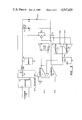
- FIG. 3 is a schematic diagram of a telephone circuit including the memory keep-alive device according to the present invention.
- FIG. 2 A block diagram of a telephone circuit incorporating a preferred embodiment of the present invention memory keep alive device is shown in FIG. 2.
- a telephone line is coupled through an on hook/off hook switch 12' to a telephone set 11a'.
- the telephone set supplies 500 microamps through a telephone set power bus Udd.
- a memory device 13' is shown connected to the telephone set internal power bus.
- Capacitor C2 supplies a keep alive current to memory device 13'.
- Capacitor C2 is typically a 5-10 farad device, such as manufactured by either Panasonic or NEC of Japan and marketed under the trademark GOLD SUPER CAPACITORS.
- the telephone line typically provides equipment operating power in the range of 20-75 volts.
- Line power is supplied to capacitor C2 through a trickle charge resistor R2.
- the trickle charge resistor is chosen to provide no more than 5 microamps to the capacitor during on-hook (not in use) telephone operation.
- Memory device 13' is typically of the type that requires at least 2 milliamps to maintain the memory contents intact.
- the trickle charge provided by resistor R2 to capacitor C2 is insufficient to maintain a memory keep alive charge on capacitor C2 for long intervals. Accordingly, the capacitor is not able to maintain the memory contents intact with only a trickle charging power source.
- line power is coupled via telephone set power bus Udd to memory device 13' to maintain the memory's contents intact.
- Line power is also coupled to capacitor C2 via the internal telephone power bus. Typically, 100 microamps are available to "top up” or charge capacitor C2.
- the amount of power available for charging capacitor C2 in either the on-hook or the off-hook mode of operation depends upon the operation of other telephone extensions connected to the same telephone line in a phone installation. When other telephone sets are off-hook, additional power is drawn from the telephone line and there is therefore less available to charge capacitor C2.
- the present invention provides a comparator 15 to monitor the charge on capacitor C2 and, in the event of an inadequate charge for maintaining the memory contents intact, to operate a transistor Q1 to bypass (short) trickle charge resistor R2. As a result, the full amount of line power available via the telephone lines is coupled directly to capacitor C2. In this way, a full charging current is provided to capacitor C2.
- capacitor C2 must supply at least 2.1 volts to memory device 13'.
- comparator 15 senses a low charge condition.
- Comparator 15 provides a corresponding control signal which operates transistor Q1 to couple the line through the transistor to capacitor C2. The line is so coupled until capacitor C2 is charged to a selected upper voltage limit.
- the upper voltage limit is 3.9 volts. It should be appreciated that the upper and lower voltage limits are determined in accordance with the requirements of the memory devices that are to be kept alive. In the exemplary embodiment of present invention, CMOS memory devices are used because of their low power requirements.
- FIG. 3 A schematic diagram of a telephone circuit including an exemplary embodiment of the present invention is shown in FIG. 3.
- Telephone set 11a' is shown coupled to a telephone line via a polarity correcting rectifier 16.
- On-hook/off-hook switch 12' provides line power, shown as current source I1, to the internal telephone power bus Udd when the telephone is off-hook.
- Power supplied by current source I2 is coupled through diode D2 to charge capacitor C2.
- Power provided to capacitor C2 is a "topping up" current. That is, during off-hook operation current source I2 supplies whatever line power is available after operating the telephone set and any extension telephone sets directly to capacitor C2.
- the line power supplied in this way is typically in excess of the line power provided via the trickle charge circuit, discussed above.
- capacitor C2 When the telephone set is on-hook, capacitor C2 provides keep alive power to memory device 13' through diode D1. Current is coupled from the telephone line from between rectifier 16 and on-hook/off-hook switch 12' through trickle charge resistor R2. As discussed above, an on-hook condition also provides line power to capacitor C2.
- a comparator circuit consisting of comparators U3 and U4 monitors the voltage supplied by capacitor C1 to determine if the capacitor's charge is sufficient to maintain the contents of memory 13' intact (2.1 volts in the preferred embodiment of the invention). Comparators U3 and U4 also monitor an upper voltage limit which corresponds to a full capacitor charge (3.9 volts in the preferred embodiment of the invention).
- comparator U4 When a low voltage is sensed at capacitor C2 by comparator U4, a high signal output is clocked through flip flop 17. The signal output from flip flop 17, in turn, operates transistor switch Q1, which bypasses trickle charge resistor R2 and couples line power from the telephone line directly to capacitor C2.
- trickle charge resistor R2 It is not always desirable to bypass trickle charge resistor R2 and provide direct line power to capacitor C2. If an extension telephone set is off-hook, dialing or conversation may be degraded or otherwise subject to annoying interference as a result of directly coupling the line power to capacitor C2. If a ringing voltage is coupled directly to capacitor C2, it may also inadvertently be coupled to the memory device and other sensitive telephone set circuitry. Such ringing voltage typically exceeds the operating limits of such memory devices, and can damage or ruin them. To prevent these problems resulting from inadequate or excessive line power, a second comparator circuit, consisting of comparators U1 and U2, is provided.
- Comparator U1 senses an upper line voltage limit (75 volts in the exemplary embodiment of the present invention) and provides a low input to flip flop 17 in the event an upper line voltage limit is detected, as in the case of a ringing voltage.
- Comparator U2 senses a low line voltage limit and provides a low input to flip flop 17 in the event a low line voltage limit is detected, as in the case of an extension telephone set being off-hook. Detection of either a low voltage or a high voltage limit inhibits operation of the exemplary embodiment of the present invention.
- a sleep timer 18 is provided to maintain the present invention in an inactive condition during a selected interval of time. Periodically, the timer provides an enable signal to comparator circuits U1/U2 and U3/U4, which circuits then sense the voltage present at capacitor C2. The circuit is operated to charge capacitor C2, if necessary, and if sensed line voltages permit. When a low capacitor charge condition is detector and line power is connected directly to capacitor C2, the exemplary embodiment of the present invention operates as described above and continues to so operate until a sufficient charge is detected at capacitor C2. The control signal produced by flip flop 17 to operate transistor switch Q1 also inhibits operation of timer 18. This arrangement is shown by the lead line connected from the Q output of flip flop 17 to the EN line of timer 18.
- timer 18 is a sleep timer which checks capacitor charge at chosen intervals.
- timer 18 checks voltage levels at the capacitor once every minute for 5-10 second intervals. Other such intervals may be chosen as are appropriate for the circuit to which the present invention is applied.
Abstract
Description
Claims (10)
Priority Applications (1)
| Application Number | Priority Date | Filing Date | Title |
|---|---|---|---|
| US06/577,105 US4547629A (en) | 1984-02-06 | 1984-02-06 | Energy management circuit |
Applications Claiming Priority (1)
| Application Number | Priority Date | Filing Date | Title |
|---|---|---|---|
| US06/577,105 US4547629A (en) | 1984-02-06 | 1984-02-06 | Energy management circuit |
Publications (1)
| Publication Number | Publication Date |
|---|---|
| US4547629A true US4547629A (en) | 1985-10-15 |
Family
ID=24307299
Family Applications (1)
| Application Number | Title | Priority Date | Filing Date |
|---|---|---|---|
| US06/577,105 Expired - Fee Related US4547629A (en) | 1984-02-06 | 1984-02-06 | Energy management circuit |
Country Status (1)
| Country | Link |
|---|---|
| US (1) | US4547629A (en) |
Cited By (22)
| Publication number | Priority date | Publication date | Assignee | Title |
|---|---|---|---|---|
| US4647787A (en) * | 1985-02-04 | 1987-03-03 | Gte Communication Systems Corp. | Backup battery power supply for microprocessor based telephones |
| GB2183942A (en) * | 1985-12-02 | 1987-06-10 | Gte Telecom Spa | Power supply circuit for telephone apparatus |
| US4675898A (en) * | 1984-12-07 | 1987-06-23 | Buscom Systems, Inc. | Single tone telephone receiver |
| WO1987004580A1 (en) * | 1986-01-21 | 1987-07-30 | Aquatrol Corporation | Low-powered remote sensor and telephone line transmitter |
| US4723269A (en) * | 1985-12-23 | 1988-02-02 | Compaq Telecommunications Corporation | Method and apparatus for power-up of unattended computer |
| US4860346A (en) * | 1986-12-22 | 1989-08-22 | Protel, Inc. | Telephone system and method operated from central office loop current |
| US4893332A (en) * | 1986-05-12 | 1990-01-09 | Aquatrol Corporation | Low-powered remote sensor |
| US4905187A (en) * | 1986-01-31 | 1990-02-27 | Rca Lincensing Corporation | Time-keeping apparatus |
| US4962485A (en) * | 1988-02-16 | 1990-10-09 | Citizen Watch Co., Ltd. | Noncontacting IC card supplied with power from an outside source |
| US4984267A (en) * | 1990-01-29 | 1991-01-08 | Nynex Corporation | Backup power supply at subscriber terminal |
| US5007027A (en) * | 1988-05-16 | 1991-04-09 | Fujitsu Limited | Data protection system in a data processing system |
| US5014308A (en) * | 1989-02-09 | 1991-05-07 | Alcatel, N.V. | Circuit arrangement for providing power for an IC chip in a telephone subset |
| US5016127A (en) * | 1988-03-23 | 1991-05-14 | Sony Corporation | Mechanism for transporting and receiving large and small tape cassettes |
| US5569997A (en) * | 1993-10-04 | 1996-10-29 | Ford Motor Company | Power supply for volatile memory devices and portable electrical appliance in vehicles |
| EP0687098A3 (en) * | 1994-05-13 | 1996-12-18 | Compaq Computer Corp | Telephone line sourced power supply |
| EP1011258A2 (en) * | 1998-12-16 | 2000-06-21 | Lucent Technologies Inc. | Telephone line-powered power supply for ancillary equipment and method of operating thereof |
| US6114830A (en) * | 1997-09-17 | 2000-09-05 | Luo; Ching-Hsing | Infrared remote controller using solar rechargeable capacitor |
| US6141416A (en) * | 1996-08-29 | 2000-10-31 | Siemens Aktiengesellschaft | Analog telephone subscriber terminal apparatus |
| US6301344B1 (en) | 1997-11-05 | 2001-10-09 | Protel, Inc. | Intelligent public telephone system and method |
| US6404165B1 (en) * | 1997-09-29 | 2002-06-11 | Mitsubishi Jidosha Kogyo | Electricity accumulator |
| US20070029968A1 (en) * | 2005-08-08 | 2007-02-08 | Siemens Vdo Automotive Corporation | Minimum battery voltage detection and measurement |
| US20110291665A1 (en) * | 2010-05-27 | 2011-12-01 | Oki Semiconductor Co., Ltd. | Timer circuit |
Citations (2)
| Publication number | Priority date | Publication date | Assignee | Title |
|---|---|---|---|---|
| US4197425A (en) * | 1977-08-10 | 1980-04-08 | The Post Office | Power supply circuit for a subscriber's telephone set |
| US4467265A (en) * | 1981-01-15 | 1984-08-21 | Wide-Lite International Corporation | Battery charger |
-
1984
- 1984-02-06 US US06/577,105 patent/US4547629A/en not_active Expired - Fee Related
Patent Citations (2)
| Publication number | Priority date | Publication date | Assignee | Title |
|---|---|---|---|---|
| US4197425A (en) * | 1977-08-10 | 1980-04-08 | The Post Office | Power supply circuit for a subscriber's telephone set |
| US4467265A (en) * | 1981-01-15 | 1984-08-21 | Wide-Lite International Corporation | Battery charger |
Cited By (27)
| Publication number | Priority date | Publication date | Assignee | Title |
|---|---|---|---|---|
| US4675898A (en) * | 1984-12-07 | 1987-06-23 | Buscom Systems, Inc. | Single tone telephone receiver |
| US4647787A (en) * | 1985-02-04 | 1987-03-03 | Gte Communication Systems Corp. | Backup battery power supply for microprocessor based telephones |
| GB2183942A (en) * | 1985-12-02 | 1987-06-10 | Gte Telecom Spa | Power supply circuit for telephone apparatus |
| US4723269A (en) * | 1985-12-23 | 1988-02-02 | Compaq Telecommunications Corporation | Method and apparatus for power-up of unattended computer |
| WO1987004580A1 (en) * | 1986-01-21 | 1987-07-30 | Aquatrol Corporation | Low-powered remote sensor and telephone line transmitter |
| US4691344A (en) * | 1986-01-21 | 1987-09-01 | Aquatrol Corporation | Low-powered remote sensor and telephone line transmitter |
| US4905187A (en) * | 1986-01-31 | 1990-02-27 | Rca Lincensing Corporation | Time-keeping apparatus |
| US4893332A (en) * | 1986-05-12 | 1990-01-09 | Aquatrol Corporation | Low-powered remote sensor |
| US4860346A (en) * | 1986-12-22 | 1989-08-22 | Protel, Inc. | Telephone system and method operated from central office loop current |
| US4962485A (en) * | 1988-02-16 | 1990-10-09 | Citizen Watch Co., Ltd. | Noncontacting IC card supplied with power from an outside source |
| US5016127A (en) * | 1988-03-23 | 1991-05-14 | Sony Corporation | Mechanism for transporting and receiving large and small tape cassettes |
| US5007027A (en) * | 1988-05-16 | 1991-04-09 | Fujitsu Limited | Data protection system in a data processing system |
| US5014308A (en) * | 1989-02-09 | 1991-05-07 | Alcatel, N.V. | Circuit arrangement for providing power for an IC chip in a telephone subset |
| US4984267A (en) * | 1990-01-29 | 1991-01-08 | Nynex Corporation | Backup power supply at subscriber terminal |
| US5569997A (en) * | 1993-10-04 | 1996-10-29 | Ford Motor Company | Power supply for volatile memory devices and portable electrical appliance in vehicles |
| EP0687098A3 (en) * | 1994-05-13 | 1996-12-18 | Compaq Computer Corp | Telephone line sourced power supply |
| US6141416A (en) * | 1996-08-29 | 2000-10-31 | Siemens Aktiengesellschaft | Analog telephone subscriber terminal apparatus |
| US6114830A (en) * | 1997-09-17 | 2000-09-05 | Luo; Ching-Hsing | Infrared remote controller using solar rechargeable capacitor |
| US6404165B1 (en) * | 1997-09-29 | 2002-06-11 | Mitsubishi Jidosha Kogyo | Electricity accumulator |
| US6850607B2 (en) | 1997-11-05 | 2005-02-01 | Protel, Inc. | Intelligent vending system and method |
| US6301344B1 (en) | 1997-11-05 | 2001-10-09 | Protel, Inc. | Intelligent public telephone system and method |
| EP1011258A3 (en) * | 1998-12-16 | 2004-06-09 | Lucent Technologies Inc. | Telephone line-powered power supply for ancillary equipment and method of operating thereof |
| EP1011258A2 (en) * | 1998-12-16 | 2000-06-21 | Lucent Technologies Inc. | Telephone line-powered power supply for ancillary equipment and method of operating thereof |
| US20070029968A1 (en) * | 2005-08-08 | 2007-02-08 | Siemens Vdo Automotive Corporation | Minimum battery voltage detection and measurement |
| US7696717B2 (en) * | 2005-08-08 | 2010-04-13 | Continental Automotive Systems Us, Inc. | Battery energy management system for measuring a minimum battery voltage |
| US20110291665A1 (en) * | 2010-05-27 | 2011-12-01 | Oki Semiconductor Co., Ltd. | Timer circuit |
| US8922223B2 (en) * | 2010-05-27 | 2014-12-30 | Lapis Semiconductor Co., Ltd. | Timer circuit |
Similar Documents
| Publication | Publication Date | Title |
|---|---|---|
| US4547629A (en) | Energy management circuit | |
| EP0693815B1 (en) | Auxiliary battery charge control circuits | |
| US20020028701A1 (en) | Power switching unit of a portable telephone | |
| US4288865A (en) | Low-power battery backup circuit for semiconductor memory | |
| JPS59501239A (en) | Telephone line power supply control device in the telephone | |
| US5251179A (en) | Apparatus and method for extending battery life | |
| WO1998012791A1 (en) | System and method for automatically enabling rapid charging of a battery in a portable phone | |
| US5668463A (en) | Auxiliary battery charge control circuit | |
| US5014308A (en) | Circuit arrangement for providing power for an IC chip in a telephone subset | |
| JP3778709B2 (en) | Battery pack | |
| US6608900B1 (en) | Load management system for an electrical device | |
| EP0090035A1 (en) | Voltage regulation and battery dissipation limiter circuit | |
| US6778665B1 (en) | Distribution of current draw in a line powered DAA | |
| US6687371B1 (en) | Maintaining an off-hook condition during a call bridge | |
| US6674857B1 (en) | Startup procedure for international line powered DAA | |
| US6979915B2 (en) | Portable equipment with backup battery charging function | |
| US4591666A (en) | Protection circuitry for subscriber's telephone circuit equipped with repertory memory | |
| KR940005522B1 (en) | Reset circuit | |
| KR200205019Y1 (en) | Charging apparatus for electric power back-up of terminal applying telephone line | |
| US6735305B1 (en) | Detection of low tip/ring currents in a line powered DAA | |
| JP2620798B2 (en) | Backup power supply circuit for telephone dial memory | |
| JP2546098Y2 (en) | Charging circuit | |
| KR970010379B1 (en) | Data protecting apparatus of credit card checking system | |
| KR200157748Y1 (en) | Electrostatic compensation circuit | |
| KR920002337Y1 (en) | Timer reset circuit using condensors |
Legal Events
| Date | Code | Title | Description |
|---|---|---|---|
| AS | Assignment |
Owner name: COMDIAL TECHNOLOGY CORPORATION 714 E. EVELYN AVE., Free format text: ASSIGNMENT OF ASSIGNORS INTEREST.;ASSIGNOR:CORLESS, ROBERT W.;REEL/FRAME:004247/0747 Effective date: 19840104 |
|
| REMI | Maintenance fee reminder mailed | ||
| LAPS | Lapse for failure to pay maintenance fees | ||
| STCH | Information on status: patent discontinuation |
Free format text: PATENT EXPIRED DUE TO NONPAYMENT OF MAINTENANCE FEES UNDER 37 CFR 1.362 |
|
| FP | Lapsed due to failure to pay maintenance fee |
Effective date: 19891015 |
|
| AS | Assignment |
Owner name: SILICON VALLEY BANK, CALIFORNIA Free format text: SECURITY INTEREST;ASSIGNOR:COMDIAL CORPORATION;REEL/FRAME:014615/0087 Effective date: 20040428 Owner name: SILICON VALLEY BANK, CALIFORNIA Free format text: SECURITY INTEREST;ASSIGNOR:COMDIAL CORPORATION;REEL/FRAME:014615/0102 Effective date: 20040428 |
|
| AS | Assignment |
Owner name: COLUMBIA PARTNERS, L.L.C. INVESTMENT MANAGEMENT, A Free format text: SECURITY AGREEMENT;ASSIGNORS:VERTICAL COMMUNICATIONS, INC.;VERTICAL COMMUNICATIONS ACQUISITION CORP.;REEL/FRAME:018407/0598 Effective date: 20061019 |