US4558217A - Multiplexing and calibration techniques for optical signal measuring instruments - Google Patents
Multiplexing and calibration techniques for optical signal measuring instruments Download PDFInfo
- Publication number
- US4558217A US4558217A US06/468,189 US46818983A US4558217A US 4558217 A US4558217 A US 4558217A US 46818983 A US46818983 A US 46818983A US 4558217 A US4558217 A US 4558217A
- Authority
- US
- United States
- Prior art keywords
- optical
- temperature
- measuring system
- light
- fibers
- Prior art date
- Legal status (The legal status is an assumption and is not a legal conclusion. Google has not performed a legal analysis and makes no representation as to the accuracy of the status listed.)
- Expired - Fee Related
Links
Images


Classifications
-
- G—PHYSICS
- G01—MEASURING; TESTING
- G01K—MEASURING TEMPERATURE; MEASURING QUANTITY OF HEAT; THERMALLY-SENSITIVE ELEMENTS NOT OTHERWISE PROVIDED FOR
- G01K11/00—Measuring temperature based upon physical or chemical changes not covered by groups G01K3/00, G01K5/00, G01K7/00 or G01K9/00
- G01K11/32—Measuring temperature based upon physical or chemical changes not covered by groups G01K3/00, G01K5/00, G01K7/00 or G01K9/00 using changes in transmittance, scattering or luminescence in optical fibres
- G01K11/3206—Measuring temperature based upon physical or chemical changes not covered by groups G01K3/00, G01K5/00, G01K7/00 or G01K9/00 using changes in transmittance, scattering or luminescence in optical fibres at discrete locations in the fibre, e.g. using Bragg scattering
- G01K11/3213—Measuring temperature based upon physical or chemical changes not covered by groups G01K3/00, G01K5/00, G01K7/00 or G01K9/00 using changes in transmittance, scattering or luminescence in optical fibres at discrete locations in the fibre, e.g. using Bragg scattering using changes in luminescence, e.g. at the distal end of the fibres
-
- G—PHYSICS
- G01—MEASURING; TESTING
- G01K—MEASURING TEMPERATURE; MEASURING QUANTITY OF HEAT; THERMALLY-SENSITIVE ELEMENTS NOT OTHERWISE PROVIDED FOR
- G01K15/00—Testing or calibrating of thermometers
Definitions
- This invention relates generally to the acquisition and processing of optical signals derived from measuring transducers, utilized, for example, in an electro-optic instrument that detects and displays temperature from an optical temperature transducer.
- a material that exhibits a change in some optical property is either applied directly to the object or made as part of a temperature probe, such as a probe formed on the end of an optical fiber.
- a temperature probe such as a probe formed on the end of an optical fiber.
- One such material is a phosphor that exhibits some change in its light emission as a function of its temperature in response to appropriate radiation excitation.
- Measuring the decay time of a phosphor emission after a pulse of exciting radiation, and the measurement of phosphor emission color chift as a function of temperature are two such methods that are described in U.S. Pat. No. 4,223,226--Quick et al. (1980).
- a decay time technique is also disclosed in U.S. Pat. No. 4,245,507--Samulski (1981).
- the preferred phosphor is one that emits sharp lines of radiation upon excitation, such as those having rare earth activators.
- a temperature measuring system utilizing such a phosphor preferably takes the ratio of emissions within two optically separable emission bands, and it is the ratio that is a function of the temperature of the phosphor. Ratioing minimizes many sources of error in the measurement, such as changes in the excitation source intensity, phosphor characteristics over time, or changes in the optical transmission system, such as an optical fiber, that communicates the phospor emission to a detecting instrument.
- the Luxtron instrument that has been marketed for some time utilizes an optical assembly positioned between an end of an optical fiber probe assembly and two detectors. These optics select two different groups of emission lines of the phosphor temperature sensor and direct the emission of one group of lines to one of the detectors and the other group of lines to the other of the detectors. These same optics direct ultraviolet radiation of a different wavelength into the optical fiber for exciting to emission the phosphor temperature sensor at the other end.
- multiplexing is provided for the simultaneous acquisition of several independent optical signals.
- Many measuring applications require readings to be taken substantially simultaneously at two or more locations.
- An improved structure for handling multiple optical signals is to physically group them together in a small bundle, such as by grouping together ends of optical fibers, and then to image these signals onto multiple individual detectors by common optical elements; that is, the multiple optical signals are imaged as one image onto multiple individual detectors from which electrical signals are independently obtained.
- An optional integrating sphere is used to provide exciting radiation to multiple transducers at the end of optical fibers, in those applications requiring exciting radiation such as with phosphor temperature transducers.
- FIG. 1 is a top view of a portion of an instrument in which the various aspects of the present invention are embodied, with certain portions cut away to show the optical system therein;
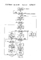
- FIG. 2 is a schematic representation of the optical system of FIG. 1, and in addition shows schematically the electronic system that operates with the optical elements;
- FIG. 3 shows in sectional view a temperature calibrating well of the instrument of FIGS. 1 and 2;
- FIG. 4 shows in side view a technique for optically processing multiple sensor signals
- FIG. 5 is a view of the optical system of FIG. 4 taken at section 5--5 thereof;
- FIG. 6 is a view of the optical system of FIG. 4 taken at section 6--6 thereof.
- FIG. 7 shows in side view a technique for providing excitation radiation to a plurality of optical fibers
- FIG. 8 is a view of the optical system of FIG. 4 taken at section 8--8 thereof;
- FIG. 9 shows an alternative technique for providing illumination to multiple fibers.
- FIG. 9A illustrates another variation of a system according to FIGS. 4-7.
- An instrument housing 11 includes upright sides, such as a back wall 13. Inside the overall instrument housing is a light source housing block 15, an optical housing 17, detector assemblies 19 and 21, and an optical fiber connector receptacle 23. A standard type of available optical fiber connector 25 is attached to a length 27 of a single optical fiber, although a bundle of optical fibers could be used as well.
- the optical housing 17 is surrounded by a layer 18 of insulation and is maintained at a uniform temperature by heaters 122 and 124 that are controlled by a thermocouple 121.
- an optical temperature sensor At a free end 29 of the optical fiber 27 is an optical temperature sensor.
- the sensor includes a small amount of phosphor material attached to the end of an optical fiber and encapsulated, the details of which are disclosed in the aforementioned Wickersheim patents.
- the luminescent signal can be obtained from phosphor spaced a distance from the optical fiber end but optically coupled with the end.
- the phosphor utilized is europium-doped lanthanum oxysulfide. This rare-earth phosphor is excited by passing ultraviolet radiation from the instrument down the optical fiber 27. Visible radiation emitted from the phosphor is then passed back along the optical fiber 27 to the instrument.
- Two groups of sharp emission lines are, in this specific example, utilized by the instrument to determine the temperature of the phosphor sensor 29. These groups include red lines around 7043 angstroms and yellow lines around 5860 angstroms. The emission intensity in these lines vary independently of each other as a function of phosphor temperature. The ratio of these intensities varies in a known way as a function of temperature.
- a light source 31 provides the phosphor exciting ultraviolet radiation. Ultraviolet radiation is preferred for the particular embodiment being described but other radiation bands could be selected for this and other embodiments. For example, longer wavelengths such as blue or green are appropriate exciting rasiation for very long optical fibers. Visible exciting radiation is also advantageously used when fluorescence of plastic optical elements excited by ultraviolet radiation is a problem.
- the optics within the housing 17 selects the red emission lines and applies it to a photodetector 33. Similarly, the optics selects the yellow emission lines and applies it to a detector 35.
- Each of the preamplifier and detector units are preferably formed as a unitary structure that is shielded from interference by stray fields.
- a quartz lens 49 takes the light emitted from the small filament of the bulb 31 and collimates it into a beam 51 that is initially passed through a filter 53 that is designed to block all but the excitation frequencies, in this specific example being within the ultra-violet range.
- the beam is reflected off three dichroic mirrors 54, 55 and 61 held in tandem. These mirrors are selected to be highly reflective to excitation radiation while allowing the detected wavelengths to pass through them. Absorbing coatings 57 and 59 are applied to the back of two of these mirrors.
- the excitation light is then reflected from the third dichroic mirror 61 to a quartz lens 63 that focuses the collimated beam onto the end of the optical fiber 27 that is positioned within the receptacle 23.
- the optical system for the visible radiation that enters from the optical fiber 27 will now be described.
- the mirror 61 and lens 63 are common both to the return fluorescence light path and the excitation radiation path.
- the lens 63 takes the light at the end of the optical fiber 27 and collimates it, directing the collimated beam against the mirror 61.
- the dichroic mirror 61 is chosen to have a crossover wavelength such that it is highly reflective to the ultraviolet source radiation but highly transmissive to the visible radiation, thereby resulting in the visible fluorescent radiation passing through it as a beam 65.
- the dichroic mirror 61 thus also acts as a filter, reflecting any ultra-violet radiation back to the source and keeping it from reaching the detector region.
- the radiation beam 65 contains the full spectrum of visible fluorescent radiation from the phosphor temperature sensor. Since only narrow wavelength ranges are of interest, additional optical elements are provided to separate the wavelengths of interest from the broad visible spectrum in the beam 65.
- a dichroic mirror 67 is selected in this particular example to transmit through a filter 69 and a lens 71 the red emission lines of interest to the detector 33.
- the dichroic mirror 67 is selected to reflect the yellow emission lines of interest onto a regular mirror 73 and thence through a filter 75 and then focused by lens 77 on the small area detector 35.
- the filters 69 and 75 are designed to pass a narrow bandwidth of the red and yellow emission lines of interest.
- an electronic system is illustrated in general terms that cooperates with the optical system described to process the information from it and to control its operation.
- a ratio is taken of the analog signal levels in the circuits 41 and 43, and it is that ratio that is related to the temperature of the phosphor in the sensor 29 in a known way.
- a simple analog system could be utilized or it could even be done by hand if the voltage levels in the circuits 41 and 43 were independently measured. But with the current sophistication in digital electronics and the wide availability of circuit chips makes a digital implementation preferred. Further, the use of a microprocessor 91 as a central controlling element of the system is desired.
- the signal voltage in the circuit 41 is amplified by amplifier 93 which has a variable gain.
- the output of that amplifier is applied directly to a digital multiplexer 95; similarly, the other circuit 43 is applied to an input of a variable gain amplifier 99 whose output is applied directly as another input to the multiplexer 95.
- the well 111 is preferably made of a heat conductive material, such as aluminum, and is of sufficient mass to have considerable thermal inertia.
- a small hole drilled into the metal is used to receive the temperature sensor 29 which, through the instrument, then reads the temperature within the well 111.
- On the side of the well 111 is a semiconductor device 115 installed in a groove provided in the metal. The device 115 allows a signal to be developed in the circuit 117 that is proportional to the temperature of the well 111, and thus of the phosphor temperature sensor 29 positioned in it.
- the signal in the circuit 117 is amplified by an amplifier 119 and applied by a circuit 100 as a third input to the multiplexer 95.
- the well 112 has a temperature measuring semiconductor element 116 which is connected by a circuit 118 to an amplifier 120, and thence through a circuit 101 to the multiplexer 95 as a fourth input.
- the temperature wells 111 and 112 are utilized for calibrating the instrument. By developing an electrical signal proportional to its temperature, the system can automatically calibrate itself.
- the well 111 is placed in close proximity, and preferably in contact with, the thermally conductive block 17. This will maintain the well 111 at an elevated temperature.
- the reference temperature well 112 is positioned within the instrument a distance removed from the block 17 and is maintained at a cooler temperature, nearer to the room ambient temperature.
- the temperatures of the two wells can be set near the extremes of temperatures to be measured, thus facilitating a two point calibration technique described below.
- the multiplexer 95 selectes one of the four inputs at a time under the control of the microprocessor 91.
- the selected input is then converted from its analog form to a digital form by a converter 105.
- the output, in digital form, of the analog-to-digital converter 105 is utilized by the microprocessor 91 as an input data from which the temperature of the sensor 29 is determined and the instrument is calibrated.
- the microprocessor 91 operates under the control of a read only memory 107.
- An electrically erasable read-only-memory (EEROM) 108 is used to store a temperature look-up table, described below.
- Output circuits 109 receive the processed information from the microprocessor 91 and include the output in the form desired for any particular application.
- the temperature information in digital form could also, or alternatively, be applied to other digital processing equipment.
- the output circuits 109 could also, or alternatively, include a digital-to-analog converter for driving a chart recorder.
- a keyboard 110 is provided for inputing information and commands to the system.
- FIGS. 4-9 techniques for adapting the instrument to measure multiple temperatures is shown.
- FIGS. 4-6 show a modification wherein a plurality of optical fiber ends 25' are utilized, each carrying an independent optical signal.
- six optical fibers are closely packed around a central core fiber, all of them having the same cross-sectional dimensions.
- Each of these fibers is optically coupled at its opposite end (not shown) to a phosphor temperature sensor of the type described previously.
- Each temperature sensor may be positioned at a unique place in an object that is monitored, or on different objects.
- the independent optical signals from each sensor are then imaged by an optical system 10' onto a detector surface 33'.
- the optical system 10' can be made essentially the same as the optical system 10 described previously with respect to FIGS. 1 and 2.
- the closely grouped optical fibers are positioned at the optical axis of the system 10' in order to avoid distortion and aberrations.
- a small, compact image located at the optical axis of various optical element means that these elements can be made inexpensively.
- the detector surface 33' preferably has an integrated multi-detector element positioned coincident with it, this element being shown in FIG. 6. Seven independent detectors are arranged so that each receives the light from one of the optical fibers 25'.
- the electrical signals generated are processed in the same manner discussed previously, either at the same time with parallel paths of equipment or, preferably, one at a time in rapid sequence by a common microprocessor based system of the type shown in FIG. 2.
- a bundle of optical fibers in the shape of the fibers 25' shown in FIG. 5 can be positioned at the surface 33' in place of the integrated detector to receive each of the individual signals.
- An opposite end of each optical fiber could then contain a discrete detector component.
- the fibers are fanned out from the small small bundle where it receives the image, to their ends containing the detectors. This structure has the advantage of giving more room for the detectors while still maintaining a very small optical image of the array of signals.
- the optical fibers 25' can be fanned out and each connected individually to a length of optical fiber with a temperature sensor on its end. That is, each of the optical fibers of the bundle 25' would have an individual connector. Alternatively, a single connector could be utilized for all of the fibers with the fibers then fanning out outside of the optical instrument into the individual fibers with temperature sensors on their ends. In either case, the temperature sensing phosphor need not be physically attached to the fiber, but rather can be attached to another object, with its emissions coupled into its associated optical fiber. A liquid fluorescent dye can alternatively be used.
- the optics 10' include everything shown in the optical system 10 of FIG. 2, including the excitation source and the splitting of the luminescent lines onto two detector arrays of the type shown in FIG. 6 for detecting the intensity of the same two lines of luminescence from each of the sensors in the manner that they may be compared for determing the temperature of the sensor.
- FIGS. 7 and 8 show an advantageous way to couple an excitation radiation source into the fiber bundle 25'.
- a sphere 131 contains two light sources 132 and 133 and is enclosed except for an array of holes 134 that are arranged to match the pattern of optical fibers 25' into which light is to be imaged.
- An interior surface of the sphere 131 is made to have a high degree of light diffusion and is non-absorptive so that an even high intensity is presented at the apertures 134.
- the light sources can be of any convenient type, incandescent, gas discharge, light emitting diode (LED), etc.
- the use of the integrating sphere 131 makes efficient use of virtually any available light source for even, efficient distribution in a pattern which matches the optical fiber pattern.
- each of the optical fibers 25' carry both the excitation radiation to its associated phosphor sensor and the luminescent radiation from the sensor to the optical system 10'.
- a more conventional fiber illumination arrangement such as shown in FIG. 9, can be used.
- a light source 135 can be positioned directly in front of excitation fibers 136, but it is preferable to interpose lenses 137 therebetween to maximize light efficiency.
- one or two fibers of each bundle may be used for continuous calibration, if desired.
- An end of any such calibration fiber carrying the phosphor probe can be left in one of the temperature wells 111 or 112. It a second calibration fiber of a bundle is employed, its sensor can be placed in the other well. The instrument can then be calibrated according to the techiques discussed below.
- An alternative source arrangement includes attaching separate sources, such as LED's, to the ends of a plurality of short fibers. The other fiber ends are then bundled to provide the desired source intensity pattern that can be substituted for the pattern of apertures 134 in the system of FIG. 7. Yet a different source is a multi-segment LED whose segments directly produce the desired source pattern shown in FIG. 8, the LED segments forming a pattern that corresponds to that of the holes 134. The LED pattern is then imaged directly onto the fiber bundle 25' (FIG. 7), one segment per fiber, taking the place of the sphere 131.
- separate sources such as LED's
- FIG. 9A An example of such a system is shown in FIG. 9A.
- a modulator 301 having individual energization circuits 303 connected to specific light elements (that make up the source 134') for each sensor fiber or fibers, it is possible to substitute a single element detector 33" for the multi-detector array 33' (FIGS. 4 and 6) and still obtain independent information for each sensor. In this case, all of the fibers 25" are imaged onto the detector element 33".
- An optical system 10 interconnects the sensor fibers, excitation source and detector.
- a single electronic signal output of the detector 33" is demodulated by a circuit 305 into individual signals in lines 307 corresponding to the optical signals of the various sensors.
- a linking circuit 309 will be provided for synchronization of the circuits 301 and 305.
- One such modulation technique is to modulate each excitation LED at a unique frequency and then electrically or digitally analyze the output of the single common detector to recover the various signals corresponding to each sensor. If the source modulation frequencies are not harmonically related (that is, no one frequency is an integer multiple of another), then lock-in synchronous detection, either electrical or digital, provides an efficient means of separating the detected sensor signals. Still another modulation and detection scheme using a single detector and multiple excitation LED's is to pulse each LED or LED segment to emission at a separate time and assign the response at the common detector to the sensor which has been excited.
Abstract
Description
Claims (11)
Priority Applications (3)
| Application Number | Priority Date | Filing Date | Title |
|---|---|---|---|
| US06/468,189 US4558217A (en) | 1982-03-12 | 1983-02-25 | Multiplexing and calibration techniques for optical signal measuring instruments |
| EP83102433A EP0092047A3 (en) | 1982-03-12 | 1983-03-11 | Multiplexing and calibration techniques for optical signal measuring instruments |
| CA000423526A CA1199198A (en) | 1982-03-12 | 1983-03-14 | Multiplexing and calibration techniques for optical signal measuring instruments |
Applications Claiming Priority (2)
| Application Number | Priority Date | Filing Date | Title |
|---|---|---|---|
| US35764582A | 1982-03-12 | 1982-03-12 | |
| US06/468,189 US4558217A (en) | 1982-03-12 | 1983-02-25 | Multiplexing and calibration techniques for optical signal measuring instruments |
Related Parent Applications (1)
| Application Number | Title | Priority Date | Filing Date |
|---|---|---|---|
| US35764582A Continuation-In-Part | 1982-03-12 | 1982-03-12 |
Publications (1)
| Publication Number | Publication Date |
|---|---|
| US4558217A true US4558217A (en) | 1985-12-10 |
Family
ID=26999738
Family Applications (1)
| Application Number | Title | Priority Date | Filing Date |
|---|---|---|---|
| US06/468,189 Expired - Fee Related US4558217A (en) | 1982-03-12 | 1983-02-25 | Multiplexing and calibration techniques for optical signal measuring instruments |
Country Status (3)
| Country | Link |
|---|---|
| US (1) | US4558217A (en) |
| EP (1) | EP0092047A3 (en) |
| CA (1) | CA1199198A (en) |
Cited By (22)
| Publication number | Priority date | Publication date | Assignee | Title |
|---|---|---|---|---|
| US4679157A (en) * | 1983-09-14 | 1987-07-07 | Omron Tateisi Electronics Co. | Temperature measuring apparatus |
| US4679934A (en) * | 1985-08-08 | 1987-07-14 | The United States Of America As Represented By The Secretary Of The Air Force | Fiber optic pyrometry with large dynamic range |
| EP0248111A2 (en) * | 1986-04-08 | 1987-12-09 | CV Technology, Incorporated | Spectroscopic method and apparatus for optically measuring temperature |
| US4750139A (en) * | 1985-01-24 | 1988-06-07 | Accufiber, Inc. | Blackbody radiation sensing optical fiber thermometer system |
| US4778987A (en) * | 1984-07-06 | 1988-10-18 | Saaski Elric W | Optical measuring device using a spectral modulation sensor having an optically resonant structure |
| US4792689A (en) * | 1985-11-12 | 1988-12-20 | The United States Of America As Represented By The Department Of Health And Human Services | Method for obtaining a ratio measurement for correcting common path variations in intensity in fiber optic sensors |
| US4845647A (en) * | 1985-01-24 | 1989-07-04 | Accufiber, Inc. | Method and apparatus for determining temperature in a blackbody radiation sensing system |
| US5051578A (en) * | 1989-11-15 | 1991-09-24 | Slemon Charles S | Self calibrating fiber optic sensor system with optimized throughput |
| US5211480A (en) * | 1990-10-18 | 1993-05-18 | Rosemount Inc. | TRD temperature sensor and electronics |
| US5255980A (en) * | 1990-10-18 | 1993-10-26 | Rosemount Inc. | Black body TRD temperature sensor |
| US20020168140A1 (en) * | 2001-04-03 | 2002-11-14 | Fujikura Ltd. | Collimator lens, fiber collimator and optical parts |
| US6494616B1 (en) | 2000-08-04 | 2002-12-17 | Regents Of The University Of Minnesota | Multiplexed sensor array |
| US20030177774A1 (en) * | 2001-02-22 | 2003-09-25 | Malone Christopher G. | Spray cooling system with cooling regime detection |
| US20050106876A1 (en) * | 2003-10-09 | 2005-05-19 | Taylor Charles A.Ii | Apparatus and method for real time measurement of substrate temperatures for use in semiconductor growth and wafer processing |
| US20060176930A1 (en) * | 2005-02-07 | 2006-08-10 | Yoo Jung Y | Method for measuring temperature in microscale |
| US20070171958A1 (en) * | 2006-01-23 | 2007-07-26 | Anh Hoang | Electrical device measurement probes |
| US20090245326A1 (en) * | 2008-03-31 | 2009-10-01 | Yamatake Corporation | Fluorescence temperature sensor |
| US8201996B1 (en) | 2008-04-25 | 2012-06-19 | Ipitek, Inc. | Passive wavelength-division multiplexing (WDM) fiber-optic temperature sensor |
| US8206030B1 (en) * | 2008-05-19 | 2012-06-26 | Ipitek, Inc. | Multiple sensing tip optical fiber thermometer |
| US10996117B1 (en) * | 2020-05-31 | 2021-05-04 | Accelovant Technologies Corporation | Integrated active fiber optic temperature measuring device |
| US11047747B2 (en) * | 2017-03-27 | 2021-06-29 | Firouzeh Sabri | Light weight flexible temperature sensor kit |
| US11353369B2 (en) | 2020-11-05 | 2022-06-07 | Accelovant Technologies Corporation | Optoelectronic transducer module for thermographic temperature measurements |
Families Citing this family (4)
| Publication number | Priority date | Publication date | Assignee | Title |
|---|---|---|---|---|
| EP0213239A1 (en) * | 1985-07-29 | 1987-03-11 | Milton Schonberger | Disposable thermometer probe and rating technique therefor |
| US5036194A (en) * | 1990-02-27 | 1991-07-30 | Allied-Signal Inc. | Lens system for optic temperature sensor |
| US5112137A (en) * | 1991-04-10 | 1992-05-12 | Luxtron Corporation | Temperature measurement with combined photo-luminescent and black body sensing techniques |
| CA2888096A1 (en) * | 2013-03-14 | 2014-09-25 | Primex Wireless, Inc. | Method and apparatus for probe calibration |
Citations (39)
| Publication number | Priority date | Publication date | Assignee | Title |
|---|---|---|---|---|
| US2546160A (en) * | 1947-10-31 | 1951-03-27 | Bela A Lengyel | Phosphorescent screen for radio wave detection |
| US2551650A (en) * | 1949-02-11 | 1951-05-08 | Eastman Kodak Co | Measurement of temperature distribution on the surface of solid bodies |
| US2656479A (en) * | 1950-08-29 | 1953-10-20 | Rca Corp | Mount for electron discharge devices |
| US2718597A (en) * | 1951-11-01 | 1955-09-20 | Exxon Research Engineering Co | Infrared analysis apparatus |
| US2987704A (en) * | 1956-12-21 | 1961-06-06 | Information Systems Inc | Variable monitoring and recording apparatus |
| US3139752A (en) * | 1959-03-16 | 1964-07-07 | American Radiator & Standard | Dual thermoelement system for measuring rapidly changing fluid temperatures and thermo-elements therefor |
| US3256518A (en) * | 1959-07-27 | 1966-06-14 | Hewitt D Crane | Thermochromic indicating system |
| US3286524A (en) * | 1963-06-04 | 1966-11-22 | Boeing Co | Thermal measuring apparatus |
| US3617745A (en) * | 1970-05-19 | 1971-11-02 | Us Army | Photometer radiometer irradiance reference source |
| US3798366A (en) * | 1972-03-06 | 1974-03-19 | R Winkler | Infrared imaging system |
| US3925727A (en) * | 1973-09-28 | 1975-12-09 | Bell Telephone Labor Inc | Optical sampling oscilloscope utilizing organ arrays of optical fibers |
| US3932023A (en) * | 1974-11-18 | 1976-01-13 | E. I. Du Pont De Nemours & Company | Optical coupler for transmitting light linearly between a single point and plural points |
| US3935463A (en) * | 1974-12-05 | 1976-01-27 | Milton Roy Company | Spectrophotometer |
| US3941487A (en) * | 1973-04-16 | 1976-03-02 | Beckman Instruments, Inc. | Colorimetric fluid analyzer |
| US4016761A (en) * | 1974-04-18 | 1977-04-12 | The United States Of America As Represented By The Secretary Of The Navy | Optical temperature probe |
| US4030362A (en) * | 1975-12-22 | 1977-06-21 | John Dimeff | Self-calibrating radiometer |
| US4062043A (en) * | 1974-03-28 | 1977-12-06 | Siemens Aktiengesellschaft | Apparatus for distributing light signals among a plurality of receivers |
| US4061578A (en) * | 1976-04-05 | 1977-12-06 | Marcos Kleinerman | Infrared detection and imaging, method and apparatus |
| US4075493A (en) * | 1976-12-16 | 1978-02-21 | Ronald Alves | Optical temperature measurement technique utilizing phosphors |
| US4122719A (en) * | 1977-07-08 | 1978-10-31 | Environmental Systems Corporation | System for accurate measurement of temperature |
| US4145142A (en) * | 1977-11-28 | 1979-03-20 | The United States Of America As Represented By The Secretary Of The Army | Apparatus for and method of testing direct-view image intensifiers |
| US4162399A (en) * | 1977-09-16 | 1979-07-24 | Bei Electronics, Inc. | Optical encoder with fiber optics |
| US4170731A (en) * | 1976-08-30 | 1979-10-09 | Miller Fluid Power Corporation | Fiber optic control modules and system employing the same |
| US4215275A (en) * | 1977-12-07 | 1980-07-29 | Luxtron Corporation | Optical temperature measurement technique utilizing phosphors |
| US4223217A (en) * | 1977-05-12 | 1980-09-16 | Eaton Corporation | Fiber optic electric switch |
| US4223226A (en) * | 1978-07-26 | 1980-09-16 | Rockwell International Corporation | Fiber optic temperature sensor |
| US4229798A (en) * | 1978-01-30 | 1980-10-21 | Alistair Francis McDermott | Liquid storage tank contents gauge |
| US4245507A (en) * | 1979-09-10 | 1981-01-20 | Samulski Thaddeus V | Temperature probe |
| US4249076A (en) * | 1977-11-23 | 1981-02-03 | Asea Aktiebolag | Optical measuring device using optical fibers |
| US4278349A (en) * | 1978-06-26 | 1981-07-14 | Asea Aktiebolag | Fiber optical temperature sensors |
| US4302970A (en) * | 1980-05-09 | 1981-12-01 | United Technologies Corporation | Optical temperature probe employing rare earth absorption |
| US4303984A (en) * | 1979-12-14 | 1981-12-01 | Honeywell Inc. | Sensor output correction circuit |
| US4304461A (en) * | 1977-07-19 | 1981-12-08 | Plessey Handel Und Investments Ag. | Optical fibre connectors |
| US4313344A (en) * | 1978-12-05 | 1982-02-02 | Asea Aktiebolag | Fiber optical temperature measurement devices |
| US4334774A (en) * | 1979-12-31 | 1982-06-15 | Bell Telephone Laboratories, Incorporated | Alignment of optical components |
| US4349886A (en) * | 1979-03-27 | 1982-09-14 | Ibar Jean Pierre | Device for modifying or controlling the shape of an electrical output signal |
| US4367040A (en) * | 1979-05-29 | 1983-01-04 | Tokyo Shibaura Denki Kabushiki Kaisha | Multi-channel optical sensing system |
| US4394714A (en) * | 1981-03-06 | 1983-07-19 | James Rote | Step lighting system |
| US4409476A (en) * | 1980-06-16 | 1983-10-11 | Asea Aktiebolag | Fiber optic temperature-measuring apparatus |
Family Cites Families (2)
| Publication number | Priority date | Publication date | Assignee | Title |
|---|---|---|---|---|
| SE415397B (en) * | 1978-06-02 | 1980-09-29 | Asea Ab | FIBEROPTICAL METDON |
| IT1099865B (en) * | 1978-10-31 | 1985-09-28 | Gavazzi Carlo Spa | EQUIPMENT FOR THE GENERATION OF ELECTROMOTORIC FORCES AND / OR ELECTRIC CURRENTS AND / OR ELECTRIC SIGNALS IN GENERAL SUITABLE FOR SIMULATING THERMOCOUPLES, RESISTANCE THERMOMETERS AND PHYSICAL VARIABLE METERS WITH ELECTRIC OUTPUT |
-
1983
- 1983-02-25 US US06/468,189 patent/US4558217A/en not_active Expired - Fee Related
- 1983-03-11 EP EP83102433A patent/EP0092047A3/en not_active Withdrawn
- 1983-03-14 CA CA000423526A patent/CA1199198A/en not_active Expired
Patent Citations (39)
| Publication number | Priority date | Publication date | Assignee | Title |
|---|---|---|---|---|
| US2546160A (en) * | 1947-10-31 | 1951-03-27 | Bela A Lengyel | Phosphorescent screen for radio wave detection |
| US2551650A (en) * | 1949-02-11 | 1951-05-08 | Eastman Kodak Co | Measurement of temperature distribution on the surface of solid bodies |
| US2656479A (en) * | 1950-08-29 | 1953-10-20 | Rca Corp | Mount for electron discharge devices |
| US2718597A (en) * | 1951-11-01 | 1955-09-20 | Exxon Research Engineering Co | Infrared analysis apparatus |
| US2987704A (en) * | 1956-12-21 | 1961-06-06 | Information Systems Inc | Variable monitoring and recording apparatus |
| US3139752A (en) * | 1959-03-16 | 1964-07-07 | American Radiator & Standard | Dual thermoelement system for measuring rapidly changing fluid temperatures and thermo-elements therefor |
| US3256518A (en) * | 1959-07-27 | 1966-06-14 | Hewitt D Crane | Thermochromic indicating system |
| US3286524A (en) * | 1963-06-04 | 1966-11-22 | Boeing Co | Thermal measuring apparatus |
| US3617745A (en) * | 1970-05-19 | 1971-11-02 | Us Army | Photometer radiometer irradiance reference source |
| US3798366A (en) * | 1972-03-06 | 1974-03-19 | R Winkler | Infrared imaging system |
| US3941487A (en) * | 1973-04-16 | 1976-03-02 | Beckman Instruments, Inc. | Colorimetric fluid analyzer |
| US3925727A (en) * | 1973-09-28 | 1975-12-09 | Bell Telephone Labor Inc | Optical sampling oscilloscope utilizing organ arrays of optical fibers |
| US4062043A (en) * | 1974-03-28 | 1977-12-06 | Siemens Aktiengesellschaft | Apparatus for distributing light signals among a plurality of receivers |
| US4016761A (en) * | 1974-04-18 | 1977-04-12 | The United States Of America As Represented By The Secretary Of The Navy | Optical temperature probe |
| US3932023A (en) * | 1974-11-18 | 1976-01-13 | E. I. Du Pont De Nemours & Company | Optical coupler for transmitting light linearly between a single point and plural points |
| US3935463A (en) * | 1974-12-05 | 1976-01-27 | Milton Roy Company | Spectrophotometer |
| US4030362A (en) * | 1975-12-22 | 1977-06-21 | John Dimeff | Self-calibrating radiometer |
| US4061578A (en) * | 1976-04-05 | 1977-12-06 | Marcos Kleinerman | Infrared detection and imaging, method and apparatus |
| US4170731A (en) * | 1976-08-30 | 1979-10-09 | Miller Fluid Power Corporation | Fiber optic control modules and system employing the same |
| US4075493A (en) * | 1976-12-16 | 1978-02-21 | Ronald Alves | Optical temperature measurement technique utilizing phosphors |
| US4223217A (en) * | 1977-05-12 | 1980-09-16 | Eaton Corporation | Fiber optic electric switch |
| US4122719A (en) * | 1977-07-08 | 1978-10-31 | Environmental Systems Corporation | System for accurate measurement of temperature |
| US4304461A (en) * | 1977-07-19 | 1981-12-08 | Plessey Handel Und Investments Ag. | Optical fibre connectors |
| US4162399A (en) * | 1977-09-16 | 1979-07-24 | Bei Electronics, Inc. | Optical encoder with fiber optics |
| US4249076A (en) * | 1977-11-23 | 1981-02-03 | Asea Aktiebolag | Optical measuring device using optical fibers |
| US4145142A (en) * | 1977-11-28 | 1979-03-20 | The United States Of America As Represented By The Secretary Of The Army | Apparatus for and method of testing direct-view image intensifiers |
| US4215275A (en) * | 1977-12-07 | 1980-07-29 | Luxtron Corporation | Optical temperature measurement technique utilizing phosphors |
| US4229798A (en) * | 1978-01-30 | 1980-10-21 | Alistair Francis McDermott | Liquid storage tank contents gauge |
| US4278349A (en) * | 1978-06-26 | 1981-07-14 | Asea Aktiebolag | Fiber optical temperature sensors |
| US4223226A (en) * | 1978-07-26 | 1980-09-16 | Rockwell International Corporation | Fiber optic temperature sensor |
| US4313344A (en) * | 1978-12-05 | 1982-02-02 | Asea Aktiebolag | Fiber optical temperature measurement devices |
| US4349886A (en) * | 1979-03-27 | 1982-09-14 | Ibar Jean Pierre | Device for modifying or controlling the shape of an electrical output signal |
| US4367040A (en) * | 1979-05-29 | 1983-01-04 | Tokyo Shibaura Denki Kabushiki Kaisha | Multi-channel optical sensing system |
| US4245507A (en) * | 1979-09-10 | 1981-01-20 | Samulski Thaddeus V | Temperature probe |
| US4303984A (en) * | 1979-12-14 | 1981-12-01 | Honeywell Inc. | Sensor output correction circuit |
| US4334774A (en) * | 1979-12-31 | 1982-06-15 | Bell Telephone Laboratories, Incorporated | Alignment of optical components |
| US4302970A (en) * | 1980-05-09 | 1981-12-01 | United Technologies Corporation | Optical temperature probe employing rare earth absorption |
| US4409476A (en) * | 1980-06-16 | 1983-10-11 | Asea Aktiebolag | Fiber optic temperature-measuring apparatus |
| US4394714A (en) * | 1981-03-06 | 1983-07-19 | James Rote | Step lighting system |
Non-Patent Citations (10)
| Title |
|---|
| "Ratioing Fluoroptic Temp. Sensor For Induced Hyperthermia" by Wickersheim et al., 6 pages, 6/1980. |
| "Recent Advances in Optical Temperature Measurement", by Wickersheim et al. (Luxtron Corp.) 8 pages, 12/1979. |
| Publ. "Automatic Self Certification of a Computer-Controlled Calibration System" by Seeley et al, IREE Transactions of Inst., vol. 1M-19, No. 4, 11/1970, pp. 245-252. |
| Publ. "Model 1000A Fluoroptic Thermometer" Luxtron Corporation, 7/1980, Bulletin (1 sheet). |
| Publ. "Recent Advances in Optical Temperature Measurement", Wickersheim & Alves, Industrial Research/Development; 12/1979. |
| Publ. Automatic Self Certification of a Computer Controlled Calibration System by Seeley et al, IREE Transactions of Inst., vol. 1M 19, No. 4, 11/1970, pp. 245 252. * |
| Publ. Model 1000A Fluoroptic Thermometer Luxtron Corporation, 7/1980, Bulletin (1 sheet). * |
| Publ. Recent Advances in Optical Temperature Measurement , Wickersheim & Alves, Industrial Research/Development; 12/1979. * |
| Ratioing Fluoroptic Temp. Sensor For Induced Hyperthermia by Wickersheim et al., 6 pages, 6/1980. * |
| Recent Advances in Optical Temperature Measurement , by Wickersheim et al. (Luxtron Corp.) 8 pages, 12/1979. * |
Cited By (33)
| Publication number | Priority date | Publication date | Assignee | Title |
|---|---|---|---|---|
| US4679157A (en) * | 1983-09-14 | 1987-07-07 | Omron Tateisi Electronics Co. | Temperature measuring apparatus |
| US4778987A (en) * | 1984-07-06 | 1988-10-18 | Saaski Elric W | Optical measuring device using a spectral modulation sensor having an optically resonant structure |
| US4845647A (en) * | 1985-01-24 | 1989-07-04 | Accufiber, Inc. | Method and apparatus for determining temperature in a blackbody radiation sensing system |
| US4750139A (en) * | 1985-01-24 | 1988-06-07 | Accufiber, Inc. | Blackbody radiation sensing optical fiber thermometer system |
| US4679934A (en) * | 1985-08-08 | 1987-07-14 | The United States Of America As Represented By The Secretary Of The Air Force | Fiber optic pyrometry with large dynamic range |
| US4792689A (en) * | 1985-11-12 | 1988-12-20 | The United States Of America As Represented By The Department Of Health And Human Services | Method for obtaining a ratio measurement for correcting common path variations in intensity in fiber optic sensors |
| EP0248111A2 (en) * | 1986-04-08 | 1987-12-09 | CV Technology, Incorporated | Spectroscopic method and apparatus for optically measuring temperature |
| US4790669A (en) * | 1986-04-08 | 1988-12-13 | Cv Technology, Inc. | Spectroscopic method and apparatus for optically measuring temperature |
| EP0248111A3 (en) * | 1986-04-08 | 1989-06-14 | CV Technology, Incorporated | Spectroscopic method and apparatus for optically measuring temperature |
| US5051578A (en) * | 1989-11-15 | 1991-09-24 | Slemon Charles S | Self calibrating fiber optic sensor system with optimized throughput |
| US5211480A (en) * | 1990-10-18 | 1993-05-18 | Rosemount Inc. | TRD temperature sensor and electronics |
| US5255980A (en) * | 1990-10-18 | 1993-10-26 | Rosemount Inc. | Black body TRD temperature sensor |
| US6494616B1 (en) | 2000-08-04 | 2002-12-17 | Regents Of The University Of Minnesota | Multiplexed sensor array |
| US20030177774A1 (en) * | 2001-02-22 | 2003-09-25 | Malone Christopher G. | Spray cooling system with cooling regime detection |
| US6817196B2 (en) * | 2001-02-22 | 2004-11-16 | Hewlett-Packard Development Company, L.P. | Spray cooling system with cooling regime detection |
| US20020168140A1 (en) * | 2001-04-03 | 2002-11-14 | Fujikura Ltd. | Collimator lens, fiber collimator and optical parts |
| US7346236B2 (en) * | 2001-04-03 | 2008-03-18 | Fujikura Ltd. | Collimator lens, fiber collimator and optical parts |
| US20050106876A1 (en) * | 2003-10-09 | 2005-05-19 | Taylor Charles A.Ii | Apparatus and method for real time measurement of substrate temperatures for use in semiconductor growth and wafer processing |
| US9239265B2 (en) | 2003-10-09 | 2016-01-19 | K-Space Associates, Inc. | Apparatus and method for real time measurement of substrate temperatures for use in semiconductor growth and wafer processing |
| US20090177432A1 (en) * | 2003-10-09 | 2009-07-09 | Taylor Ii Charles A | Apparatus and method for real time measurement of substrate temperatures for use in semiconductor growth and wafer processing |
| US20100274523A1 (en) * | 2003-10-09 | 2010-10-28 | K-Space Associates, Inc. | Apparatus and method for real time measurement of substrate temperatures for use in semiconductor growth and wafer processing |
| US7837383B2 (en) | 2003-10-09 | 2010-11-23 | K-Space Associates, Inc. | Apparatus and method for real time measurement of substrate temperatures for use in semiconductor growth and wafer processing |
| US20060176930A1 (en) * | 2005-02-07 | 2006-08-10 | Yoo Jung Y | Method for measuring temperature in microscale |
| US20070171958A1 (en) * | 2006-01-23 | 2007-07-26 | Anh Hoang | Electrical device measurement probes |
| US20090245326A1 (en) * | 2008-03-31 | 2009-10-01 | Yamatake Corporation | Fluorescence temperature sensor |
| US8308357B2 (en) * | 2008-03-31 | 2012-11-13 | Azbil Corporation | Fluorescent temperature sensor |
| US8201996B1 (en) | 2008-04-25 | 2012-06-19 | Ipitek, Inc. | Passive wavelength-division multiplexing (WDM) fiber-optic temperature sensor |
| US8206030B1 (en) * | 2008-05-19 | 2012-06-26 | Ipitek, Inc. | Multiple sensing tip optical fiber thermometer |
| US11047747B2 (en) * | 2017-03-27 | 2021-06-29 | Firouzeh Sabri | Light weight flexible temperature sensor kit |
| US10996117B1 (en) * | 2020-05-31 | 2021-05-04 | Accelovant Technologies Corporation | Integrated active fiber optic temperature measuring device |
| EP3916362A1 (en) * | 2020-05-31 | 2021-12-01 | Accelovant Technologies Corporation | Integrated active fiber optic temperature measuring device |
| CN113739951A (en) * | 2020-05-31 | 2021-12-03 | 艾科赛乐维特技术公司 | Integrated active optical fiber temperature measuring equipment |
| US11353369B2 (en) | 2020-11-05 | 2022-06-07 | Accelovant Technologies Corporation | Optoelectronic transducer module for thermographic temperature measurements |
Also Published As
| Publication number | Publication date |
|---|---|
| EP0092047A3 (en) | 1985-05-15 |
| CA1199198A (en) | 1986-01-14 |
| EP0092047A2 (en) | 1983-10-26 |
Similar Documents
| Publication | Publication Date | Title |
|---|---|---|
| US4558217A (en) | Multiplexing and calibration techniques for optical signal measuring instruments | |
| US4459044A (en) | Optical system for an instrument to detect the temperature of an optical fiber phosphor probe | |
| US5183338A (en) | Temperature measurement with combined photo-luminescent and black body sensing techniques | |
| US5112137A (en) | Temperature measurement with combined photo-luminescent and black body sensing techniques | |
| US4498004A (en) | Fiber optical measuring device, employing a sensor material with a non-linear intensity response characteristic for measuring physical quantities | |
| US4245507A (en) | Temperature probe | |
| US5307146A (en) | Dual-wavelength photometer and fiber optic sensor probe | |
| USRE31832E (en) | Temperature probe | |
| CN101819149B (en) | High performance fluorescent optical sensor | |
| US4652143A (en) | Optical temperature measurement techniques | |
| US4789992A (en) | Optical temperature measurement techniques | |
| US4708494A (en) | Methods and devices for the optical measurement of temperature with luminescent materials | |
| US4376890A (en) | Fiber-optic temperature-measuring apparatus | |
| US7507022B2 (en) | Apparatus for measuring temperature using luminescence thermometry | |
| US4661711A (en) | Fluorometer | |
| JPH09325116A (en) | Measurement device | |
| US4792689A (en) | Method for obtaining a ratio measurement for correcting common path variations in intensity in fiber optic sensors | |
| EP0560903A1 (en) | Modular luminescence-based measuring system using fast digital signal processing | |
| US5470155A (en) | Apparatus and method for measuring temperatures at a plurality of locations using luminescent-type temperature sensors which are excited in a time sequence | |
| JPS59180329A (en) | Fiber optical measuring device | |
| US5414266A (en) | Measuring system employing a luminescent sensor and methods of designing the system | |
| WO1989002072A1 (en) | Method and apparatus for optically measuring concentration of material | |
| EP0029653B1 (en) | Optical systems for sensing and measuring physical quantities | |
| US20070160500A1 (en) | Oxygen sensor and measuring method | |
| US5311013A (en) | Optical fiber distribution system for an optical fiber sensor in a luminescent sensor system |
Legal Events
| Date | Code | Title | Description |
|---|---|---|---|
| AS | Assignment |
Owner name: LUXTRON CORPORATION, A CORP. OF CA. Free format text: ASSIGNMENT OF ASSIGNORS INTEREST.;ASSIGNOR:ALVES, RONALD V.;REEL/FRAME:004122/0738 Effective date: 19830223 |
|
| AS | Assignment |
Owner name: GRACE VENTUES CORP. OFFICE OF NEW VENTURES 630 HAN Free format text: SECURITY INTEREST;ASSIGNOR:LUXTRON CORPORATION;REEL/FRAME:004444/0281 Effective date: 19850724 Owner name: MED-TECH VENTURES, INC. C/O WARNER-LAMBERT COMPANY Free format text: SECURITY INTEREST;ASSIGNOR:LUXTRON CORPORATION;REEL/FRAME:004444/0281 Effective date: 19850724 Owner name: HAMBRECHT & QUIST 235 MONTGOMERY STREET, SAN FRANC Free format text: SECURITY INTEREST;ASSIGNOR:LUXTRON CORPORATION;REEL/FRAME:004444/0281 Effective date: 19850724 |
|
| AS | Assignment |
Owner name: LUXTRON CORPORATION, A CORP. OF CA. Free format text: ASSIGNMENT OF ASSIGNORS INTEREST.;ASSIGNORS:MED-TECH VENTURES, INC.;HAMBRECHT & QUIST;GRACE VENTURES CORP.;REEL/FRAME:004508/0477;SIGNING DATES FROM 19850113 TO 19851231 |
|
| CC | Certificate of correction | ||
| REMI | Maintenance fee reminder mailed | ||
| LAPS | Lapse for failure to pay maintenance fees | ||
| STCH | Information on status: patent discontinuation |
Free format text: PATENT EXPIRED DUE TO NONPAYMENT OF MAINTENANCE FEES UNDER 37 CFR 1.362 |
|
| FP | Lapsed due to failure to pay maintenance fee |
Effective date: 19891210 |
|
| AS | Assignment |
Owner name: COMERICA BANK, MICHIGAN Free format text: SECURITY AGREEMENT;ASSIGNOR:LUXTRON CORPORATION;REEL/FRAME:023032/0742 Effective date: 20070412 |