US4558588A - Vibrating needle viscosity meter - Google Patents
Vibrating needle viscosity meter Download PDFInfo
- Publication number
- US4558588A US4558588A US06/598,001 US59800184A US4558588A US 4558588 A US4558588 A US 4558588A US 59800184 A US59800184 A US 59800184A US 4558588 A US4558588 A US 4558588A
- Authority
- US
- United States
- Prior art keywords
- viscosity
- end portion
- coil
- circuit
- measuring
- Prior art date
- Legal status (The legal status is an assumption and is not a legal conclusion. Google has not performed a legal analysis and makes no representation as to the accuracy of the status listed.)
- Expired - Lifetime
Links
Images

Classifications
-
- G—PHYSICS
- G01—MEASURING; TESTING
- G01N—INVESTIGATING OR ANALYSING MATERIALS BY DETERMINING THEIR CHEMICAL OR PHYSICAL PROPERTIES
- G01N11/00—Investigating flow properties of materials, e.g. viscosity, plasticity; Analysing materials by determining flow properties
- G01N11/10—Investigating flow properties of materials, e.g. viscosity, plasticity; Analysing materials by determining flow properties by moving a body within the material
- G01N11/16—Investigating flow properties of materials, e.g. viscosity, plasticity; Analysing materials by determining flow properties by moving a body within the material by measuring damping effect upon oscillatory body
Definitions
- the invention relates to viscosity meters of the type having a probe consisting of a straight needle which is adapted to be partially immersed in the fluid whose viscosity is to be measured.
- An intermediate portion of the needle is secured against movement to constitute a node and a portion of the needle remote from the immersed portion is provided with drive means for vibrating the needle transversally and with pick up means for delivering a signal representative of the amplitude of the vibration.
- Viscosity meters of the above-defined type have been known for score of years (French No. 899,057). However, it was found that they are not suitable for use when a high accuracy is required or/and under circumstances where the viscosity may vary in a substantial range; consequently U-shaped probes rather than needles are used in the present day mechanical vibration viscosity meters (French No. 2,353,847). On the other hand, the increased complexity of the viscosity meters using a U-shaped probe represents a definite drawback.
- the inventors have now found that the main deficiencies of the prior art needle type viscosity meters may in fact be removed if they are driven at the natural or resonance frequency of the needle; a difficulty then occurs, which is the variation of that frequency if the length of the immersed portion or the viscosity changes.
- the needle is arranged to be vibrated by a stationary drive coil fed with an A.C. energizing current by an electric circuit connected to receive a signal from the pick up means at the vibrating frequency and including a feedback loop arranged to adjust the frequency of the A.C current at the natural frequency of the needle.
- the driving coil cooperates with a ferromagnetic element, typically a permanent magnet, carried by the needle.
- the needle will typically be secured in an end wall of a tube section whose opposite end is secured to a stationary plate. Then the vibration node will usually be between the ends of the tube section.
- a measure of the viscosity of the fluid may be the magnitude of an electric signal delivered by the pick up means when a predetermined electrical power is applied to the drive coil.
- pick up means e.g. Hall elements
- the electrical current applied to the drive means is adjusted for maintaining the amplitude of the output from the pick up means at a constant value and the power is measured for providing an indication of the viscosity.
- the output from the pick up means, as well as the movement of the needle is approximately sine shaped. It is however preferable to deliver a square wave signal to the coil. It can be generated by amplifying and clipping the signal delivered by the pick up. With that approach, the vibration starts without an external action when power is applied.
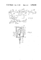
- FIG. 1 is a schematic representation of the mechanical part of a viscosity meter according to an embodiment of the invention, in cross section along an axial plane;
- FIG. 2 is a block diagram of the energizing and measuring circuit of the viscosity meter of FIG. 1;
- FIGS. 3 and 4 are block diagrams illustrating possible modifications of FIG. 2.
- the mechanical parts of a viscosity meter comprise a base member 10 adapted to be secured onto a vessel or pipe containing the liquid or pasteous product whose viscosity is to be measured.
- a tube 12 of resilient metal (typically of stainless steel) is secured in an axial opening of the base member by appropriate means, for instance by force fitting and welding.
- a cylindrical needle 14 located along the axis of tube 12 projects from both ends of the tube 12.
- An intermediate portion of the needle is secured to an end portion of the tube remote from the base member.
- the rod may be secured by silver welding or electron beam welding.
- Means are provided for inducing a transversal flexure vibratory movement of the asembly 16 consisting of needle 14 and tube 12, which will thereafter be referred to as a rod.
- the means for driving the rod into oscillation comprises a permanent magnet 18 carried by the end of the rod which is remote from the portion adapted to be dipped into the product.
- Magnet 18 is located in the air gap of an electromagnet 20 having a driving coil 22 and carried by a frame 24 fixed to the base plate 10.
- the frame 24 also carries a displacement pick up 26, which may be a Hall probe cooperating with a magnet 28 carried by the needle.
- the magnets may be carried by a cap retained on the needle by a screw.
- a protective casing 30 removably connected to the base plate 10 accomodates the mechanical components.
- the casing is formed with an opening through which the electrical components are connected to outside circuits.
- a finned sleeve 34 may be located around the casing for heat dispersal.
- FIG. 2 there is illustrated a circuit which may be associated to the components of FIG. 1.
- the circuit of FIG. 2 is adapted to measure the amount of damping, and consequently the viscosity, by determining the magnitude of the oscillation when a constant driving power is applied.
- the circuit is associated with a D.C. power source (not shown). It delivers driving signals as square signals having a constant voltage as long as the operating temperature remains unchanged. If the operating termperature range is large, the circuit can include means for compensating the variation in resistance of the coil 22 as a function of temperature.
- the pick up probe 26 consists of a Hall probe of a type which is currently available in the trade as a unit provided with its own temperature compensation circuit (Honeywell 92 SS 12-2 for instance). That probe delivers a sine shaped signal whose amplitude is in direct relation with that of the magnitude of the oscillation in a large range.
- the output of pick up probe 26 is applied to a measuring leg and a driving leg, which energizes coil 22.
- the driving leg has an open loop operational amplifier 36 having a high gain.
- Two zener diodes 38 in opposed series relation connected between the output of amplifier 36 and ground clamp the signal for transforming it into square pulses.
- the zener diodes may be diodes having a triggering voltage of 5.1 Volt, for instance BZX 46C whose characteristics hardly vary with temperature.
- the square signal is applied to a second operational amplifier 40 acting as follower. As illustrated in FIG. 2, amplifier 40 drives a summing amplifier 42 whose function will appear later. The output signal of amplifier 42 is applied to coil 22 through an operational amplifier 44 having an adjustable gain, which is used for manual gain adjustment.
- the curcuit has temperature compensation means for delivering square signals, at the output frequency of pick up probe 26, whose amplitude is variable in proportion to the temperature variation of the coil.
- the compensation means will not be described in detail, since they are quite conventional in nature and consist of operational amplifiers.
- One of the inputs of compensation means 46 receives a signal from the output of amplifier 40 and a temperature representative signal delivered by a probe 48 in close proximity to coil 22.
- the temperature probe 48 may for instance be a platinum resistance probe available from the firm THERMO-EST under reference K 201S.
- a network of resistors 50, 52 connected to the inverting input of operational amplifier 42 is used for summing the output signals from the amplifier 40 and from the compensation means 46.
- the measuring leg of the circuit includes an operational amplifier 54 connected to an output circuit having a rectifying diode 56 and a storage capacitor 58, whereby it operates as a rectifier-integrator.
- the D.C. voltage across capacitor 58 drives an impedance adaptation amplifier 60, connected as a follower.
- the output signal of amplifier 60 is applied to a recorder 62 which may be of any appropriate type.
- the viscosity meter of the invention provides for excitation of the rod at its natural frequency, whatever the viscosity of the product. It has also attendent advantages: the amplitude of the oscillating movement is measured without mechanical contact; there is no appreciable wear of the driving mechanism; the system is not sensitive to perturbations of the A.C. network, since it uses a D.C. power source. It may operate in any angular position and it is of reduced bulk.
- the viscosity meter is so located that the unit consisting of the tube 12 and that part of needle 14 which projects from the tube is immersed in the product. Electrical power is applied. Operation occurs immediately, without any need for an outside excitation.
- the electronic part may be located at a distance.
- a grommet may be located in the opening of casing 30, with passages for the wires (two wires for coil 22, three wires for the Hall probe 26 and three wires for the temperature compensation probe).
- detectors other than a Hall probe may be used. Each particular type of detector will generally require a temperature compensation circuit which is particular to that detector.
- FIG. 3 there is shown the head portion of a circuit which makes use of an electromagnetic detector 26a.
- a capacitor 64 is connected across the detector for filtering purposes.
- the signal from detector 26a is applied to a closed loop operational amplifier 40a which drives an open loop operational amplifier 36a.
- temperature compensation may use a coil 66 subjected to the same temperature as detector 26a and connected between a line toward the measuring leg and ground.
- the thermal compensation circuit associated with the driving coil 22 may sometimes be omitted by operating it at a constant current value.
- FIG. 4 there is illustrated a circuit which may be substituted to the final portion of the energizing leg of FIG. 2.
- the drive coil 22 is inserted in a feedback loop of operational amplifier 42.
- a capacitor 68 across the terminals of coil 22 may be used for adjusting resonance.
- the feedback loop is connected to ground by a resistor 70 which increases safety by limiting the value of the current.
- the operational amplifiers may be of type LM 324 or TL 084.
- a Schmitt trigger (for instance 4093 of National Semiconductors) may be located upstream of amplifier 44 for shaping the signal.
Abstract
Description
Claims (9)
Applications Claiming Priority (2)
| Application Number | Priority Date | Filing Date | Title |
|---|---|---|---|
| FR8306238 | 1983-04-15 | ||
| FR8306238A FR2544496B1 (en) | 1983-04-15 | 1983-04-15 | VIBRATING ROD VISCOSIMETER |
Publications (1)
| Publication Number | Publication Date |
|---|---|
| US4558588A true US4558588A (en) | 1985-12-17 |
Family
ID=9287922
Family Applications (1)
| Application Number | Title | Priority Date | Filing Date |
|---|---|---|---|
| US06/598,001 Expired - Lifetime US4558588A (en) | 1983-04-15 | 1984-04-09 | Vibrating needle viscosity meter |
Country Status (4)
| Country | Link |
|---|---|
| US (1) | US4558588A (en) |
| EP (1) | EP0123608B1 (en) |
| DE (1) | DE3466289D1 (en) |
| FR (1) | FR2544496B1 (en) |
Cited By (17)
| Publication number | Priority date | Publication date | Assignee | Title |
|---|---|---|---|---|
| US4704898A (en) * | 1983-02-24 | 1987-11-10 | Ernst Thone | Method and apparatus for measuring the viscosity of a liquid |
| US4754640A (en) * | 1987-03-17 | 1988-07-05 | National Metal And Refining Company, Ltd. | Apparatus and method for determining the viscoelasticity of liquids |
| US4799378A (en) * | 1985-10-21 | 1989-01-24 | Alcor, Inc. | Piezoelectric viscometer |
| DE3738901A1 (en) * | 1987-11-17 | 1989-05-24 | Amelung Gmbh Heinrich | Device for recording the change in state of a liquid |
| US4862384A (en) * | 1987-08-03 | 1989-08-29 | Rockwell International Corporation | Method of measuring the dynamic viscosity of a viscous fluid utilizing acoustic transducer |
| US4922745A (en) * | 1987-03-11 | 1990-05-08 | Rudkin Mark J | Fluid transducer |
| US5067344A (en) * | 1989-05-08 | 1991-11-26 | Natonal Metal And Refining Company, Inc. | Vibratory viscometer transducer with isolation support for inline viscosity sensor |
| US5157962A (en) * | 1989-05-08 | 1992-10-27 | National Metal And Refining Company, Inc. | Vibratory viscometer transducer with isolation support for inline viscosity sensor |
| US5723771A (en) * | 1995-03-13 | 1998-03-03 | Yamaichi Electronics Co., Ltd. | Vibratory liquid detector |
| US6105425A (en) * | 1998-04-06 | 2000-08-22 | Nohken Inc. | Vibration type level detector |
| US20020102185A1 (en) * | 2001-01-31 | 2002-08-01 | Shimadzu Corporation | Automatic sampler and needle for the same |
| US6668621B1 (en) | 2002-06-13 | 2003-12-30 | Hubert Arthur Wright | Viscosity measurement by means of damped resonant vibration normal to an approximate rigid plate |
| US20040114206A1 (en) * | 2002-12-13 | 2004-06-17 | Pillai Narayana Sateesh | Current driver for an analog micromirror device |
| WO2004055869A2 (en) * | 2002-12-13 | 2004-07-01 | Texas Instruments Incorporated | Current driver for an analog micromirror device |
| US20080117842A1 (en) * | 2006-11-20 | 2008-05-22 | Rao Roshan M | Multicast Flow Distribution |
| US20100004018A1 (en) * | 2003-06-06 | 2010-01-07 | Interdigital Technology Corporation | Adjusting the amplitude and phase characteristics of transmitter generated wireless communication signals in response to base station transmit power control signals and known transmitter amplifier characteristics |
| US20100199749A1 (en) * | 2007-07-25 | 2010-08-12 | Continental Automotive Gmbh | Arrangement for determining a characteristic variable of a fluid, sensor device and use in a motor vehicle |
Families Citing this family (2)
| Publication number | Priority date | Publication date | Assignee | Title |
|---|---|---|---|---|
| FR2911188B1 (en) * | 2007-01-10 | 2010-03-12 | Fr De Services Soc | METHOD AND SYSTEM USING OSCILLATING ELEMENT FOR DETERMINING PHYSICAL CHARACTERISTICS OF A PRODUCT |
| CA2911761C (en) | 2014-12-19 | 2017-09-05 | Dale E. Jamison | Methods for determining rheological quantities of a drilling fluid using apparent viscosity |
Citations (6)
| Publication number | Priority date | Publication date | Assignee | Title |
|---|---|---|---|---|
| FR899057A (en) * | 1942-10-22 | 1945-05-18 | Ig Farbenindustrie Ag | Viscometer for carrying out measurements and adjustments |
| GB851621A (en) * | 1957-04-29 | 1960-10-19 | Bayer Ag | Viscometer |
| US3585457A (en) * | 1969-05-01 | 1971-06-15 | Fuller Co | Material level sensing device and indicating system |
| US3710614A (en) * | 1971-09-09 | 1973-01-16 | Nat Metal & Refining Co | High precision wide dynamic range viscous loss measuring apparatus |
| US3903732A (en) * | 1974-06-17 | 1975-09-09 | Honeywell Inc | Viscosimeter and densitometer apparatus |
| US4166381A (en) * | 1978-02-24 | 1979-09-04 | E. I. Du Pont De Nemours And Company | Apparatus for determining the viscosity of fluids |
Family Cites Families (5)
| Publication number | Priority date | Publication date | Assignee | Title |
|---|---|---|---|---|
| US2550052A (en) * | 1949-02-21 | 1951-04-24 | Shell Dev | Viscosity meter |
| US3270274A (en) * | 1965-02-15 | 1966-08-30 | Automation Prod | Temperature compensating circuit |
| NL7211279A (en) * | 1971-08-20 | 1973-02-22 | ||
| FR2353847A1 (en) * | 1976-05-31 | 1977-12-30 | Commissariat Energie Atomique | Vibration viscometer for measurement of liq. under pressure - uses vibrating transmission pin with established node point |
| US4148216A (en) * | 1978-01-18 | 1979-04-10 | Do Mau T | Apparatus for determining the viscous behavior of a liquid during coagulation thereof |
-
1983
- 1983-04-15 FR FR8306238A patent/FR2544496B1/en not_active Expired
-
1984
- 1984-04-09 US US06/598,001 patent/US4558588A/en not_active Expired - Lifetime
- 1984-04-13 DE DE8484400747T patent/DE3466289D1/en not_active Expired
- 1984-04-13 EP EP84400747A patent/EP0123608B1/en not_active Expired
Patent Citations (6)
| Publication number | Priority date | Publication date | Assignee | Title |
|---|---|---|---|---|
| FR899057A (en) * | 1942-10-22 | 1945-05-18 | Ig Farbenindustrie Ag | Viscometer for carrying out measurements and adjustments |
| GB851621A (en) * | 1957-04-29 | 1960-10-19 | Bayer Ag | Viscometer |
| US3585457A (en) * | 1969-05-01 | 1971-06-15 | Fuller Co | Material level sensing device and indicating system |
| US3710614A (en) * | 1971-09-09 | 1973-01-16 | Nat Metal & Refining Co | High precision wide dynamic range viscous loss measuring apparatus |
| US3903732A (en) * | 1974-06-17 | 1975-09-09 | Honeywell Inc | Viscosimeter and densitometer apparatus |
| US4166381A (en) * | 1978-02-24 | 1979-09-04 | E. I. Du Pont De Nemours And Company | Apparatus for determining the viscosity of fluids |
Cited By (20)
| Publication number | Priority date | Publication date | Assignee | Title |
|---|---|---|---|---|
| US4704898A (en) * | 1983-02-24 | 1987-11-10 | Ernst Thone | Method and apparatus for measuring the viscosity of a liquid |
| US4799378A (en) * | 1985-10-21 | 1989-01-24 | Alcor, Inc. | Piezoelectric viscometer |
| US4922745A (en) * | 1987-03-11 | 1990-05-08 | Rudkin Mark J | Fluid transducer |
| US4754640A (en) * | 1987-03-17 | 1988-07-05 | National Metal And Refining Company, Ltd. | Apparatus and method for determining the viscoelasticity of liquids |
| US4862384A (en) * | 1987-08-03 | 1989-08-29 | Rockwell International Corporation | Method of measuring the dynamic viscosity of a viscous fluid utilizing acoustic transducer |
| DE3738901A1 (en) * | 1987-11-17 | 1989-05-24 | Amelung Gmbh Heinrich | Device for recording the change in state of a liquid |
| US5067344A (en) * | 1989-05-08 | 1991-11-26 | Natonal Metal And Refining Company, Inc. | Vibratory viscometer transducer with isolation support for inline viscosity sensor |
| US5157962A (en) * | 1989-05-08 | 1992-10-27 | National Metal And Refining Company, Inc. | Vibratory viscometer transducer with isolation support for inline viscosity sensor |
| US5723771A (en) * | 1995-03-13 | 1998-03-03 | Yamaichi Electronics Co., Ltd. | Vibratory liquid detector |
| US6105425A (en) * | 1998-04-06 | 2000-08-22 | Nohken Inc. | Vibration type level detector |
| US20020102185A1 (en) * | 2001-01-31 | 2002-08-01 | Shimadzu Corporation | Automatic sampler and needle for the same |
| US7175812B2 (en) * | 2001-01-31 | 2007-02-13 | Shimadzu Corporation | Automatic sampler and needle for the same |
| US6668621B1 (en) | 2002-06-13 | 2003-12-30 | Hubert Arthur Wright | Viscosity measurement by means of damped resonant vibration normal to an approximate rigid plate |
| US20040114206A1 (en) * | 2002-12-13 | 2004-06-17 | Pillai Narayana Sateesh | Current driver for an analog micromirror device |
| WO2004055869A2 (en) * | 2002-12-13 | 2004-07-01 | Texas Instruments Incorporated | Current driver for an analog micromirror device |
| WO2004055869A3 (en) * | 2002-12-13 | 2004-12-29 | Texas Instruments Inc | Current driver for an analog micromirror device |
| US20100004018A1 (en) * | 2003-06-06 | 2010-01-07 | Interdigital Technology Corporation | Adjusting the amplitude and phase characteristics of transmitter generated wireless communication signals in response to base station transmit power control signals and known transmitter amplifier characteristics |
| US20080117842A1 (en) * | 2006-11-20 | 2008-05-22 | Rao Roshan M | Multicast Flow Distribution |
| US20100199749A1 (en) * | 2007-07-25 | 2010-08-12 | Continental Automotive Gmbh | Arrangement for determining a characteristic variable of a fluid, sensor device and use in a motor vehicle |
| US8297111B2 (en) * | 2007-07-25 | 2012-10-30 | Continental Automotive Gmbh | Arrangement for determining a characteristic variable of a fluid, sensor device and use in a motor vehicle |
Also Published As
| Publication number | Publication date |
|---|---|
| EP0123608B1 (en) | 1987-09-16 |
| FR2544496B1 (en) | 1985-10-11 |
| FR2544496A1 (en) | 1984-10-19 |
| EP0123608A1 (en) | 1984-10-31 |
| DE3466289D1 (en) | 1987-10-22 |
Similar Documents
| Publication | Publication Date | Title |
|---|---|---|
| US4558588A (en) | Vibrating needle viscosity meter | |
| US4372164A (en) | Industrial process control instrument employing a resonant sensor | |
| US4602505A (en) | Apparatus for measuring viscosity | |
| US3712117A (en) | High precision wide dynamic range viscous loss measuring apparatus | |
| US3339400A (en) | Mass presence sensing apparatus | |
| US4655075A (en) | Vibrating tube densimeter | |
| NL8103935A (en) | DEVICE FOR DETERMINING THE REACHING OF A PRE-DEFINED FILLING POSITION IN A RESERVOIR. | |
| US4488427A (en) | Rotational vibratory viscometer transducer and circuit | |
| US3911731A (en) | Non-contacting self-calibrating vibration sensor | |
| US4566181A (en) | Rotational vibratory viscometer transducer and circuit | |
| US4166381A (en) | Apparatus for determining the viscosity of fluids | |
| US6539806B2 (en) | Fluid-load measurement by magnetic excitation and vibration sensing of a fluid-load-sensitive diaphragm | |
| US3722262A (en) | Oscillating viscometer | |
| US3225588A (en) | Densimetering systems | |
| US6112581A (en) | Vibratory viscometer | |
| US2474693A (en) | Magnetic field responsive device | |
| SU839451A3 (en) | Medium flow rate gage | |
| US4008613A (en) | Vibratory bin level indicators | |
| US3177705A (en) | Apparatus for determining viscosity of materials | |
| WO1993002347A1 (en) | Viscometer | |
| CA1224060A (en) | Vibrating needle viscosity meter | |
| US6668621B1 (en) | Viscosity measurement by means of damped resonant vibration normal to an approximate rigid plate | |
| US2251436A (en) | Vibration measuring and recording apparatus | |
| US3942369A (en) | Method of and apparatus for measuring and setting the tension of stressed members | |
| US3508437A (en) | Device for determining the internal friction of materials |
Legal Events
| Date | Code | Title | Description |
|---|---|---|---|
| AS | Assignment |
Owner name: SOCIETE FRANCAISE DE SERVICES S.A., 8, RUE NOBEL, Free format text: ASSIGNMENT OF ASSIGNORS INTEREST.;ASSIGNORS:BEAUDOIN, PAUL;MAROONE, PIERRE;REEL/FRAME:004248/0275 Effective date: 19840327 |
|
| STCF | Information on status: patent grant |
Free format text: PATENTED CASE |
|
| FEPP | Fee payment procedure |
Free format text: PAYOR NUMBER ASSIGNED (ORIGINAL EVENT CODE: ASPN); ENTITY STATUS OF PATENT OWNER: LARGE ENTITY |
|
| FPAY | Fee payment |
Year of fee payment: 4 |
|
| FEPP | Fee payment procedure |
Free format text: PAYER NUMBER DE-ASSIGNED (ORIGINAL EVENT CODE: RMPN); ENTITY STATUS OF PATENT OWNER: LARGE ENTITY Free format text: PAYOR NUMBER ASSIGNED (ORIGINAL EVENT CODE: ASPN); ENTITY STATUS OF PATENT OWNER: LARGE ENTITY |
|
| FEPP | Fee payment procedure |
Free format text: PAYER NUMBER DE-ASSIGNED (ORIGINAL EVENT CODE: RMPN); ENTITY STATUS OF PATENT OWNER: LARGE ENTITY Free format text: PAT HLDR NO LONGER CLAIMS SMALL ENT STAT AS SMALL BUSINESS (ORIGINAL EVENT CODE: LSM2); ENTITY STATUS OF PATENT OWNER: LARGE ENTITY Free format text: PAYOR NUMBER ASSIGNED (ORIGINAL EVENT CODE: ASPN); ENTITY STATUS OF PATENT OWNER: LARGE ENTITY |
|
| FPAY | Fee payment |
Year of fee payment: 8 |
|
| FPAY | Fee payment |
Year of fee payment: 12 |