US4565317A - Two-way envelope with inside return seal flap - Google Patents
Two-way envelope with inside return seal flap Download PDFInfo
- Publication number
- US4565317A US4565317A US06/534,371 US53437183A US4565317A US 4565317 A US4565317 A US 4565317A US 53437183 A US53437183 A US 53437183A US 4565317 A US4565317 A US 4565317A
- Authority
- US
- United States
- Prior art keywords
- extension
- flap
- return
- envelope
- back panel
- Prior art date
- Legal status (The legal status is an assumption and is not a legal conclusion. Google has not performed a legal analysis and makes no representation as to the accuracy of the status listed.)
- Expired - Lifetime
Links
Images


Classifications
-
- B—PERFORMING OPERATIONS; TRANSPORTING
- B65—CONVEYING; PACKING; STORING; HANDLING THIN OR FILAMENTARY MATERIAL
- B65D—CONTAINERS FOR STORAGE OR TRANSPORT OF ARTICLES OR MATERIALS, e.g. BAGS, BARRELS, BOTTLES, BOXES, CANS, CARTONS, CRATES, DRUMS, JARS, TANKS, HOPPERS, FORWARDING CONTAINERS; ACCESSORIES, CLOSURES, OR FITTINGS THEREFOR; PACKAGING ELEMENTS; PACKAGES
- B65D27/00—Envelopes or like essentially-rectangular containers for postal or other purposes having no structural provision for thickness of contents
- B65D27/06—Envelopes or like essentially-rectangular containers for postal or other purposes having no structural provision for thickness of contents with provisions for repeated re-use
Definitions
- This invention relates to envelopes and in particular to a two-way envelope adapted for use with automatic mail processing equipment.
- Two-way or returnable mailing envelopes are widely used for business transactions where a reply to an initial mailing is required. For example, many businesses send their statements in two-way envelopes which their customers use for returning payments.
- An exemplary two-way envelope is shown in the Hiersteiner U.S. Pat. No. 3,152,751 and includes a flap which is divided by a tear line into an initial seal flap portion and a return flap portion. Upon receipt by the initial addressee, the initial seal flap portion is detached from the envelope and the return flap portion is utilized to seal the envelope pocket for a return trip. Return addresses and postage may be applied to the flap.
- Hiersteiner U.S. Pat. No. 4,180,168 Another type of two-way envelope is shown in the Hiersteiner U.S. Pat. No. 4,180,168 and includes a pair of side flaps folded over a front panel to form a pocket.
- the side flaps have upper portions which form a return flap for sealing the pocket for a return mailing.
- An initial seal flap is integral with the front panel and demarcated therefrom by a tear line. The initial seal flap is folded over the return flap for an initial mailing and is detached from the envelope by the initial addressee.
- the initial address including a bar format code is preferably printed on materials enclosed in the envelope and visible through a window on the front panel thereof. It is likewise desirable for a return address on a two-way envelope to include a pre-printed zip code in bar format. Furthermore, facing identification marks which identify a return mailing as courtesy reply or business reply may be required to be printed on the outside of the envelope in its return configuration for detection by the Postal Service's automatic sorting equipment.
- a related problem occurs if a facing identification mark appropriate only to the return trip is visible during the initial trip and is detected by an optical code reader. Also, many prior art two-way envelopes did not provide sufficient space for printing a return address with a zip code in bar format and the aforementioned facing identification marks.
- the two-way envelope includes a front panel with a window opening.
- a back panel is integrally connected to the front panel and demarcated therefrom by a lower fold line.
- Side flaps extend from the front panel and are adhesively connected to the back panel.
- An initial seal flap is connected to the front panel along a perforated tear line.
- a return flap is integrally connected to the back panel and demarcated therefrom by a return flap fold line.
- An extension extends from the return flap and is foldable with respect thereto for insertion in a pocket of the envelope for an initial mailing. With the return flap and the extension folded with respect to each other for an initial mailing, interference with automatic insertion equipment for stuffing the envelopes is avoided.
- the initial seal flap is detached from the back panel and torn loose from the front panel.
- the return flap and the extension are extracted from the pocket, and folded with respect to each other and placed over the front panel with the extension in covering relation over the window opening.
- Postage and facing identification marks may be applied to the return flap and a return address including a return zip code in bar format may be applied to the extension. Gaps are provided between side edges of the front and back panels to facilitate insertion and removal of the return flap and the extension.
- the principal objects of the present invention are: to provide a two-way envelope; to provide such an envelope which is particularly well adapted for use with automatic mail processing equipment; to provide such an envelope which includes a return flap and an extension foldably connected thereto; to provide such an envelope wherein the extension is adapted for covering a window opening in a front panel of the envelope; to provide such an envelope wherein the extension may have a return address including a return zip code in bar format printed thereon; to provide such an envelope wherein the return flap and extension are folded with respect to each other and inserted in a pocket thereof for an initial mailing; to provide such an envelope with an initial seal flap which is separable therefrom along a tear line; to provide such an envelope which is compatible for use with automatic envelope stuffing equipment; to provide such an envelope which is simple and inexpensive to produce on conventional rotary envelope folding equipment; and to provide such an envelope which is easy to use, relatively inexpensive, and efficient in operation.
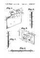
- FIG. 1 is a front perspective view of a two-way envelope embodying the present invention.
- FIG. 2 is a rear perspective view of the two-way envelope with portions broken away to reveal the internal construction thereof.
- FIG. 3 is a rear perspective view of the envelope showing an initial seal flap being removed therefrom;
- FIG. 4 is a rear perspective view of the envelope showing a return flap and an extension extracted from a pocket of the envelope and being unfolded with respect to each other.
- FIG. 5 is a front perspective view of the envelope in its return mailing configuration.
- FIG. 6 is a cross-sectional view of the envelope taken generally along line 6--6 in FIG. 1.
- FIG. 7 is a cross-sectional view of the envelope taken generally along line 7--7 in FIG. 5.
- FIG. 8 is a cross-sectional view of the envelope taken generally along line 8--8 in FIG. 1.
- FIG. 9 is a plan view of a blank for forming the envelope.
- FIG. 10 is an enlarged, front elevational view of an envelope comprising a modified embodiment of the present invention.
- FIG. 11 is a cross-sectional view of the modified envelope taken generally along line 11--11 in FIG. 10.
- FIG. 12 is an enlarged front elevational view of the modified envelope in its return configuration.
- FIG. 13 is a cross-sectional view of the modified envelope taken generally along line 13--13 in FIG. 12.
- the reference numeral 1 generally designates a two-way, or return envelope embodying the present invention.
- the envelope 1 includes a front panel 2 with inner and outer surfaces 3, 4.
- the front panel 1 includes upper, lower and side edges 5, 6 and 7 respectively.
- a window opening 8 extends through the front panel 2 and is covered by a transparent plastic window patch 9 adhesively secured to the front panel inner surface 3.
- a back panel 15 includes inner and outer surfaces 16, 17 and upper, lower and side edges 18, 19 and 20 respectively.
- the back panel 15 is integrally connected to and demarcated from the front panel 2 by a lower fold line 21 at the panel lower edges 6, 19.
- a pair of side flaps 25 each includes proximate and distal side edges 26, 27 and upper and lower ends 28, 29.
- the side flaps 25 are integrally connected to the front panel 2 and demarcated therefrom by side flap fold lines 30 extending along respective side flap proximate edges 26 and partially along respective front panel side edges 7.
- the side flaps 25 are secured to the back panel inner surface 16 by adhesive strips 31.
- the side flap upper ends 28 terminate in spaced relation below the front and back panel upper edges 5, 18 whereby gaps or side openings 32 are formed between upper portions of the front and back panel side edges 7, 20 for purposes which will be explained more fully hereinafter.
- An initial seal flap 40 includes proximate, distal and side edges 41, 42 and 43 and a fold line 44 extending parallel to the proximate and distal edges 41, 42 in closely spaced relation to the proximate edge 41.
- the front panel 2 and initial seal flap 40 are connected at their respective upper and proximate edges 5, 41 at a perforated tear line 45.
- a plurality of discrete adhesive spots 46 are provided on the initial seal flap 40 adjacent its distal edge 41 for releasable attachment to the back panel outer surface 17 for an initial mailing.
- a return flap 51 includes proximate, distal and side edges 49, 50, 52 and inner and outer surfaces 59, 60.
- the return flap 51 is integrally connected to the back panel 15 and demarcated therefrom by a return flap fold line 57 extending along the back panel upper and return flap proximate edges 18, 49.
- the return flap side edges 52 are spaced apart more widely adjacent the return flap fold line 57 than adjacent the return flap distal edge 50.
- An extension 53 includes proximate, distal and side edges 54, 55 and 56 and inner and outer surfaces 61, 62.
- the extension is integrally connected to the return flap and demarcated therefrom by an extension fold line 58 extending along the return flap distal and extension proximate edges 50, 54 in parallel, spaced relation to the return flap fold line 57.
- the extension side edges 56 are spaced approximately as far apart as the return flap side edges 52 adjacent the extension fold line 58.
- An adhesive strip 63 is applied to the extension inner surface 61 along the extension distal edge 55.
- a single-piece blank 64 (FIG. 9) is cut from paper stock in a conventional manner. Suitable adhesive is applied to the blank 64 at 31, 46 and 61.
- the window patch 9 is adhesively applied to the front panel inner surface 3 in covering relation over the window opening 8.
- the return flap 51 is then folded along the extension fold line 58 so that the return flap and the extension inner surfaces 59, 61 are in opposed relation.
- the return flap 51 and the extension 53 are then folded into a pocket 66 formed between the front and back panel inner surfaces 3, 16 at the return flap fold line 57.
- the extension outer surface 62 is thus positioned in opposed relation to the back panel inner surface 16.
- the two-way envelope 1 is now in a preferred configuration for the insertion of initial material 67, for example by automatic insertion equipment, without inteference from the extension 53.
- an initial address 68 printed thereon including an initial bar code indicia 69 is visible through the window patch 9.
- the initial seal flap 40 is adhesively attached to the back panel outer surface 7, postage is applied and the envelope 1 is ready for an initial mailing.
- the initial addressee pries the initial seal flap 40 loose from the back panel outer surface 17 at the adhesive spots 46, tears the initial seal flap 40 from the front panel 2 at the perforated tear line 45 and extracts the initial material 67.
- the return flap 51 and the extension 53 are also extracted from the pocket 66 and unfolded.
- the initial addressee then inserts into the pocket 66 return material 71 which may comprise, for example, a payment, an order, information requested by the initial addressee or any other type of reply which may be handled by two-way mail communications.
- the pocket 66 is then resealed for a return trip by folding the return flap 51 and the extension 53 over the front panel outer surface 4 along the return flap fold line 57.
- the extension is secured to the front panel outer surface 4 by adhesive strip 63.
- the extension 53 covers the window opening 8 to avoid any possibility of the initial address 68 and its bar format zip code 69 appearing on the outside of the envelope 1. Therefore, if the initial recipient inadvertently leaves the initial material 67 in its original position, the initial address 68 displayed through the window opening 8 will be covered and will not affect the return routing of the envelope 1.
- the extension 53 has a return address 73 printed thereon including a return bar code indicia 74. Facing identification marks 75 indicating the nature of the return mailing as business or courtesy reply mail are printed on the return flap outer surface 60. Since the return address 73 and the return facing identification marks 75 are positioned within the pocket 66 for the initial trip, they are not visible from the outside of the envelope 1 in its initial mailing configuration and thus cannot cause the envelope 1 to be misdirected.
- the extension 53 serves two very important functions in a two-way mail transaction. First of all, the extension 53 covers the window opening 8 and thus obscures any material within the pocket 66 which might misdirect the envelope 1 on its return trip, particularly the initial address 68 on the initial material 67. Secondly, the extension outer surface 62 provides a place for preprinting the return address 73 so that it will be properly located in a position relative to the front panel 2 corresponding to that of the window opening 8 through which the initial address 68 was visible.
- the two-way envelope of the present invention is particularly well adapted for use with automatic mail processing equipment used by the U.S. Postal Service.
- Zip codes printed as bar codes are detected by bar code readers.
- Opitical character readers determine from the facing identification marks whether or not a preprinted zip code in bar format is present on the envelope and also the nature of the mail piece. If the zip code is not present in bar format, the optical character reader prints it on the envelope.
- the use of such automatic mail processing equipment poses particular problems for two-way mailings. For example, if the initial zip code in bar format shows on the return trip, the mail piece may be routed back to the initial address.
- the facing identification marks should likewise be visible only for that portion of the envelope's trip to which they are applicable.
- the two-way envelope 1 of the present invention avoids the aforementioned problems by providing a return flap 51 and extension 53 which, in their respective positions for a return mailing, prevent the initial address 68 and the initial facing identification marks 70 from being visible.
- the initial seal flap 40 is designated to be removed along the perforated tear line 45 after the initial trip, if the initial addressee neglects to do this, it may be folded between the front panel outer surface 4 and the return flap 51 or into the pocket 66 for a return mailing. In either case, it will not hinder the return mailing of the envelope 1.
- the perforated tear line 45 and the return flap fold line 57 are substantially colinear.
- the seal flap fold line 44 is spaced toward the seal flap distal edge 42 so that the seal flap 40 is easily folded over the back panel upper edge 18 for an initial trip.
- the gaps 32 are adapted to allow a letter opener (not shown) to be easily inserted into the pocket 66 for opening the envelope 2 after an initial or a return mailing.
- a letter opener may be inserted anywhere above the adhesive strip 63 to open the envelope 1 after a return trip.
- FIGS. 10 through 13 A two-way envelope comprising a modified embodiment of the present invention is shown in FIGS. 10 through 13 and generally designated by the reference numeral 101.
- the envelope 101 includes a front panel 102 integrally connected to a back panel 115 and a pair of side flaps 125.
- An initial seal flap 140 is integrally connected to the front panel 102 and demarcated therefrom by a perforated tear line 145.
- the initial seal flap 140 also includes a seal flap fold line 144 extending parallel to and slightly spaced from the perforated tear line 145.
- a return flap 151 is integrally connected to the back panel 115 and demarcated therefrom by a return flap fold line 157.
- the return flap 151 is positioned within a pocket 166 formed between the front and back panels 102, 115 for an initial mailing.
- the initial seal flap 140 is folded along the initial seal flap fold line 144 and adhesively attached to the back panel 115.
- the initial addressee detaches the initial seal flap 140 from the back panel 115 and removes it from the envelope 101 by tearing along the perforated tear line 145.
- the envelope 101 may be resealed for a return trip by extracting the return flap 151 from the pocket 166 and adhesively attaching it to the envelope front panel 102.
Abstract
Description
Claims (17)
Priority Applications (1)
| Application Number | Priority Date | Filing Date | Title |
|---|---|---|---|
| US06/534,371 US4565317A (en) | 1983-09-21 | 1983-09-21 | Two-way envelope with inside return seal flap |
Applications Claiming Priority (1)
| Application Number | Priority Date | Filing Date | Title |
|---|---|---|---|
| US06/534,371 US4565317A (en) | 1983-09-21 | 1983-09-21 | Two-way envelope with inside return seal flap |
Publications (1)
| Publication Number | Publication Date |
|---|---|
| US4565317A true US4565317A (en) | 1986-01-21 |
Family
ID=24129759
Family Applications (1)
| Application Number | Title | Priority Date | Filing Date |
|---|---|---|---|
| US06/534,371 Expired - Lifetime US4565317A (en) | 1983-09-21 | 1983-09-21 | Two-way envelope with inside return seal flap |
Country Status (1)
| Country | Link |
|---|---|
| US (1) | US4565317A (en) |
Cited By (71)
| Publication number | Priority date | Publication date | Assignee | Title |
|---|---|---|---|---|
| US4778101A (en) * | 1986-10-09 | 1988-10-18 | Jean Paquin | Two-way envelope |
| US4917287A (en) * | 1989-04-27 | 1990-04-17 | Watson William W | Reversible envelope |
| US4945218A (en) * | 1988-09-06 | 1990-07-31 | Talbott Alex F | Mailing device and machine-readable business card |
| EP0288524B1 (en) * | 1986-10-31 | 1991-08-14 | Irt Finland Limited | Procedure and means for drying moving web material |
| US5074459A (en) * | 1987-01-23 | 1991-12-24 | Neill Keith P O | Mailing envelope |
| US5165726A (en) * | 1988-09-06 | 1992-11-24 | Talbott Alex F | Mailing device and business card combination |
| US5224647A (en) * | 1991-05-21 | 1993-07-06 | Supremex Inc. | Remailable envelope |
| US5232248A (en) * | 1988-09-06 | 1993-08-03 | Talbott Alex F | Mailing device |
| US5251810A (en) * | 1992-02-21 | 1993-10-12 | Kim Myun H | Re-mailable envelope with double side addressing window |
| US5267687A (en) * | 1992-03-13 | 1993-12-07 | Sheppard Envelope Company | Two way mailer |
| US5271553A (en) * | 1991-05-03 | 1993-12-21 | Myun Ho Kim | Re-mailable envelope with removable addressing sheet |
| US5316208A (en) * | 1992-07-16 | 1994-05-31 | Glenn Petkovsek | Single layer multi-part mailer assembly |
| US5411201A (en) * | 1992-07-16 | 1995-05-02 | Petkovsek; Glenn | Single layer multi-part mailer assembly |
| US5415341A (en) * | 1992-05-21 | 1995-05-16 | Diamond Gamma, L.L.C. | Business envelope |
| US5431337A (en) * | 1994-07-08 | 1995-07-11 | Leslie J. Bell | Reply mail envelope |
| US5468945A (en) * | 1994-02-25 | 1995-11-21 | Intermec Corporation | Method and apparatus for locating and decoding a postnet forwarding bar code in a field of postnet bar codes |
| US5507526A (en) * | 1992-07-16 | 1996-04-16 | Glenn Petkovsek | Single layer multi-part mailer assembly |
| US5516040A (en) * | 1994-02-01 | 1996-05-14 | Lin; Sheng C. | Two way mailing envelopes |
| US5697648A (en) * | 1995-04-20 | 1997-12-16 | Petkovsek; Glenn | Integral special service mailing assembly and a method for using same |
| US5713511A (en) * | 1992-05-21 | 1998-02-03 | Diamond; Elliott H. | Multi-purpose envelope |
| US5746450A (en) * | 1995-04-20 | 1998-05-05 | Petkovsek; Glenn | Integral special service mailing assembly with a cut out portion and a method for using same |
| US5803352A (en) * | 1996-12-24 | 1998-09-08 | Spaulding; Lincoln Brooks | Two way mailer |
| US5826787A (en) * | 1994-11-04 | 1998-10-27 | Fraser Envelopes Ltd. | Two-way mailer envelope |
| US5915730A (en) * | 1997-06-18 | 1999-06-29 | Petkovsek; Glenn | Special service mailing assembly with receipt and label and a method for preparing a mailpiece for delivery |
| US5918802A (en) * | 1994-11-01 | 1999-07-06 | Petkovsek; Glenn | Special service envelope and a method for mailing a mailpiece requiring a special service |
| US5951053A (en) * | 1995-04-20 | 1999-09-14 | Petkovsek; Glenn | Integral special service mailing assembly and a method for using same |
| US5967403A (en) * | 1998-07-01 | 1999-10-19 | Tension Envelope Corporation | Remailable envelope and method for making a remailable envelope from a single blank |
| US5970458A (en) * | 1997-05-13 | 1999-10-19 | Petkovsek; Glenn | Generic special service mailing assembly and a system and method for automating the imaging of same with voice recognition and security provisions |
| US5967558A (en) * | 1995-04-20 | 1999-10-19 | Petkovsek; Glenn | Integral special service mailing assembly and a method for using same |
| US5984365A (en) * | 1997-05-13 | 1999-11-16 | Petkovsek; Glenn | Generic special service mailing assembly and a system and method for automating the imaging of same |
| US6003902A (en) * | 1997-05-13 | 1999-12-21 | Petkovsek; Glenn | Generic special service mailing assembly and a method for using same |
| US6070792A (en) * | 1998-09-22 | 2000-06-06 | Rock-Tenn Company | Reusable envelope |
| US6120063A (en) * | 1995-04-20 | 2000-09-19 | Petkovsek; Glenn | Integral special service mailing assembly with removable special service designator section and a method for using same |
| US6192661B1 (en) | 1997-04-29 | 2001-02-27 | R. R. Donnelley & Sons | Return envelope assembly |
| US6203068B1 (en) | 1997-06-18 | 2001-03-20 | Glenn Petkovsek | Special service mailing assembly with label, tracking area and receipt and a method for preparing a mailpiece for delivery |
| US6290262B1 (en) | 1996-10-04 | 2001-09-18 | Glenn Petkovsek | Continuous special service labels and a method for preparing a mailpiece for delivery by special service |
| US6388764B2 (en) | 1997-05-13 | 2002-05-14 | Glenn Petkovsek | Generic special service mailing assembly and a system and method for automating the imaging of same |
| US20030160097A1 (en) * | 2002-02-28 | 2003-08-28 | Gerald Steiner | Package and method for merchandise return via mail |
| US20040050918A1 (en) * | 2002-09-18 | 2004-03-18 | Delavergne Carol A. | Environmentally friendly reusable envelope structures |
| US20050061866A1 (en) * | 2003-08-22 | 2005-03-24 | K & H Printers-Lithographers, Inc. | Voting ballot envelope |
| US20050071297A1 (en) * | 1995-10-11 | 2005-03-31 | Stamps.Com Inc. | System and method for generating personalized postage indicia |
| US20050184140A1 (en) * | 2004-02-25 | 2005-08-25 | Ecoenvelopes, Llc | Reusable envelope structures and methods |
| US20050230458A1 (en) * | 2001-10-03 | 2005-10-20 | Richard Kranz | Envelope having improved overlap profile |
| US20060087113A1 (en) * | 2004-10-27 | 2006-04-27 | Snyder Aric N | Pre-converted roll stock for forming return envelopes and packaging |
| US20060173796A1 (en) * | 1995-10-11 | 2006-08-03 | Kara Salim G | System and method for printing multiple postage indicia |
| US20060219769A1 (en) * | 2005-04-05 | 2006-10-05 | Ecoenvelopes, Llc | Reusable envelope structures and methods |
| US20060266808A1 (en) * | 2005-05-26 | 2006-11-30 | Ecoenvelopes, Llc | Envelope structures and methods |
| US20070084907A1 (en) * | 2001-10-03 | 2007-04-19 | Richard Kranz | Envelope having improved overlap profile |
| US20080021849A1 (en) * | 1995-10-11 | 2008-01-24 | Stamps.Com Inc | System and method for printing multiple postage indicia |
| US20080041928A1 (en) * | 2006-08-18 | 2008-02-21 | Delavergne Carol A | Reusable envelopes |
| US20100038414A1 (en) * | 2008-07-10 | 2010-02-18 | Delavergne Carol A | Reusable mailers and methods |
| US20100089991A1 (en) * | 2008-10-10 | 2010-04-15 | Robinson Iii Lon Stephen | Two-way envelope |
| US20110068161A1 (en) * | 2004-09-09 | 2011-03-24 | Dan Perrone | Two way electronic media mailer |
| US20110168770A1 (en) * | 2009-11-12 | 2011-07-14 | Pregis Innovative Packaging, Inc. | Tear-propagation resistant envelope |
| US20120217304A1 (en) * | 2011-02-24 | 2012-08-30 | Myplace, Inc. | System and method for authorizing a right or benefit |
| US8763891B1 (en) | 2004-02-25 | 2014-07-01 | Carol A. DeLaVergne | Reusable envelope structures and methods |
| US8875985B1 (en) | 2009-02-19 | 2014-11-04 | eco Envelopes, LLC. | Conversion envelopes |
| US9617041B1 (en) * | 2009-02-19 | 2017-04-11 | Ecoenvelopes, Llc. | Conversion envelopes |
| DE102015117371A1 (en) * | 2015-10-13 | 2017-04-13 | Matthias Knoblauch | Closure element for reclosing an opened shipping envelope |
| US9842308B1 (en) | 2010-02-25 | 2017-12-12 | Stamps.Com Inc. | Systems and methods for rules based shipping |
| US9878825B1 (en) | 2015-06-02 | 2018-01-30 | Ecoenvelopes, Llc | Reusable top flap envelope with dual opposing seal flaps |
| US9911246B1 (en) | 2008-12-24 | 2018-03-06 | Stamps.Com Inc. | Systems and methods utilizing gravity feed for postage metering |
| US9914320B1 (en) | 2011-04-21 | 2018-03-13 | Stamps.Com Inc. | Secure value bearing indicia using clear media |
| US9978185B1 (en) | 2008-04-15 | 2018-05-22 | Stamps.Com Inc. | Systems and methods for activation of postage indicia at point of sale |
| US10089797B1 (en) | 2010-02-25 | 2018-10-02 | Stamps.Com Inc. | Systems and methods for providing localized functionality in browser based postage transactions |
| US10373398B1 (en) | 2008-02-13 | 2019-08-06 | Stamps.Com Inc. | Systems and methods for distributed activation of postage |
| US10373216B1 (en) | 2011-10-12 | 2019-08-06 | Stamps.Com Inc. | Parasitic postage indicia |
| US10713634B1 (en) | 2011-05-18 | 2020-07-14 | Stamps.Com Inc. | Systems and methods using mobile communication handsets for providing postage |
| US10846650B1 (en) | 2011-11-01 | 2020-11-24 | Stamps.Com Inc. | Perpetual value bearing shipping labels |
| US10922641B1 (en) | 2012-01-24 | 2021-02-16 | Stamps.Com Inc. | Systems and methods providing known shipper information for shipping indicia |
| US11037151B1 (en) | 2003-08-19 | 2021-06-15 | Stamps.Com Inc. | System and method for dynamically partitioning a postage evidencing system |
Citations (21)
| Publication number | Priority date | Publication date | Assignee | Title |
|---|---|---|---|---|
| GB190314185A (en) * | 1903-06-25 | 1903-07-30 | Walter John Pearse | An Improved Envelope. |
| US1064302A (en) * | 1911-05-27 | 1913-06-10 | Rebecca M Donohue | Envelop. |
| US1145935A (en) * | 1915-01-02 | 1915-07-13 | Henry A Steinke | Return-reply envelop. |
| US1373512A (en) * | 1919-11-29 | 1921-04-05 | Kuhhorn John | Return-envelop |
| US2201538A (en) * | 1938-06-03 | 1940-05-21 | John A Holden | Envelope |
| US2317335A (en) * | 1939-08-09 | 1943-04-20 | Curtis 1000 Inc | Envelope |
| US2936946A (en) * | 1953-11-16 | 1960-05-17 | Harpman Sol | Send-and-return envelopes |
| US3152751A (en) * | 1963-02-04 | 1964-10-13 | Tension Envelope Corp | Two-way envelope and enclosure combination |
| US3270948A (en) * | 1965-05-14 | 1966-09-06 | Donovan Marion | Two-way envelope |
| US3356285A (en) * | 1965-08-30 | 1967-12-05 | Craig P Greason | Envelope |
| US3498528A (en) * | 1968-07-26 | 1970-03-03 | Tension Envelope Corp | Remailable envelope |
| US3512702A (en) * | 1968-10-31 | 1970-05-19 | Us Plywood Champ Papers Inc | Send and return mailing envelope and package |
| US3558040A (en) * | 1968-05-25 | 1971-01-26 | Lloyd H Krueger | Two-way envelope |
| US3982689A (en) * | 1975-07-14 | 1976-09-28 | Fergus Retrum | Returnable mailing envelope |
| US4081127A (en) * | 1976-06-15 | 1978-03-28 | Wallace Business Forms, Inc. | Return envelope for mailer and method |
| US4180168A (en) * | 1978-07-13 | 1979-12-25 | Tension Envelope Corporation | Two-way envelope |
| US4288028A (en) * | 1980-01-07 | 1981-09-08 | Diaz Jose O | Remailable envelope |
| US4308987A (en) * | 1980-01-22 | 1982-01-05 | Merrill Solomon | Remailable envelope |
| US4332346A (en) * | 1981-02-12 | 1982-06-01 | 21St Century Envelope Co. Inc. | Two-way envelope |
| US4382539A (en) * | 1981-06-08 | 1983-05-10 | Kronman Albert F | Two-way envelopes with return flap positioning means and method |
| US4445635A (en) * | 1981-05-01 | 1984-05-01 | Barr Arthur C | Two way mailing envelope |
-
1983
- 1983-09-21 US US06/534,371 patent/US4565317A/en not_active Expired - Lifetime
Patent Citations (22)
| Publication number | Priority date | Publication date | Assignee | Title |
|---|---|---|---|---|
| GB190314185A (en) * | 1903-06-25 | 1903-07-30 | Walter John Pearse | An Improved Envelope. |
| US1064302A (en) * | 1911-05-27 | 1913-06-10 | Rebecca M Donohue | Envelop. |
| US1145935A (en) * | 1915-01-02 | 1915-07-13 | Henry A Steinke | Return-reply envelop. |
| US1373512A (en) * | 1919-11-29 | 1921-04-05 | Kuhhorn John | Return-envelop |
| US2201538A (en) * | 1938-06-03 | 1940-05-21 | John A Holden | Envelope |
| US2317335A (en) * | 1939-08-09 | 1943-04-20 | Curtis 1000 Inc | Envelope |
| US2936946A (en) * | 1953-11-16 | 1960-05-17 | Harpman Sol | Send-and-return envelopes |
| US3152751A (en) * | 1963-02-04 | 1964-10-13 | Tension Envelope Corp | Two-way envelope and enclosure combination |
| US3270948A (en) * | 1965-05-14 | 1966-09-06 | Donovan Marion | Two-way envelope |
| US3356285A (en) * | 1965-08-30 | 1967-12-05 | Craig P Greason | Envelope |
| US3558040A (en) * | 1968-05-25 | 1971-01-26 | Lloyd H Krueger | Two-way envelope |
| US3558040B1 (en) * | 1968-05-25 | 1983-11-08 | 21St Cenrury Envelope Co Inc | |
| US3498528A (en) * | 1968-07-26 | 1970-03-03 | Tension Envelope Corp | Remailable envelope |
| US3512702A (en) * | 1968-10-31 | 1970-05-19 | Us Plywood Champ Papers Inc | Send and return mailing envelope and package |
| US3982689A (en) * | 1975-07-14 | 1976-09-28 | Fergus Retrum | Returnable mailing envelope |
| US4081127A (en) * | 1976-06-15 | 1978-03-28 | Wallace Business Forms, Inc. | Return envelope for mailer and method |
| US4180168A (en) * | 1978-07-13 | 1979-12-25 | Tension Envelope Corporation | Two-way envelope |
| US4288028A (en) * | 1980-01-07 | 1981-09-08 | Diaz Jose O | Remailable envelope |
| US4308987A (en) * | 1980-01-22 | 1982-01-05 | Merrill Solomon | Remailable envelope |
| US4332346A (en) * | 1981-02-12 | 1982-06-01 | 21St Century Envelope Co. Inc. | Two-way envelope |
| US4445635A (en) * | 1981-05-01 | 1984-05-01 | Barr Arthur C | Two way mailing envelope |
| US4382539A (en) * | 1981-06-08 | 1983-05-10 | Kronman Albert F | Two-way envelopes with return flap positioning means and method |
Cited By (105)
| Publication number | Priority date | Publication date | Assignee | Title |
|---|---|---|---|---|
| US4778101A (en) * | 1986-10-09 | 1988-10-18 | Jean Paquin | Two-way envelope |
| EP0288524B1 (en) * | 1986-10-31 | 1991-08-14 | Irt Finland Limited | Procedure and means for drying moving web material |
| US5074459A (en) * | 1987-01-23 | 1991-12-24 | Neill Keith P O | Mailing envelope |
| US4945218A (en) * | 1988-09-06 | 1990-07-31 | Talbott Alex F | Mailing device and machine-readable business card |
| US5165726A (en) * | 1988-09-06 | 1992-11-24 | Talbott Alex F | Mailing device and business card combination |
| US5232248A (en) * | 1988-09-06 | 1993-08-03 | Talbott Alex F | Mailing device |
| US4917287A (en) * | 1989-04-27 | 1990-04-17 | Watson William W | Reversible envelope |
| US5271553A (en) * | 1991-05-03 | 1993-12-21 | Myun Ho Kim | Re-mailable envelope with removable addressing sheet |
| US5224647A (en) * | 1991-05-21 | 1993-07-06 | Supremex Inc. | Remailable envelope |
| US5251810A (en) * | 1992-02-21 | 1993-10-12 | Kim Myun H | Re-mailable envelope with double side addressing window |
| US5267687A (en) * | 1992-03-13 | 1993-12-07 | Sheppard Envelope Company | Two way mailer |
| US5415341A (en) * | 1992-05-21 | 1995-05-16 | Diamond Gamma, L.L.C. | Business envelope |
| US5713511A (en) * | 1992-05-21 | 1998-02-03 | Diamond; Elliott H. | Multi-purpose envelope |
| US5507526A (en) * | 1992-07-16 | 1996-04-16 | Glenn Petkovsek | Single layer multi-part mailer assembly |
| US5411201A (en) * | 1992-07-16 | 1995-05-02 | Petkovsek; Glenn | Single layer multi-part mailer assembly |
| US5316208A (en) * | 1992-07-16 | 1994-05-31 | Glenn Petkovsek | Single layer multi-part mailer assembly |
| US5516040A (en) * | 1994-02-01 | 1996-05-14 | Lin; Sheng C. | Two way mailing envelopes |
| US5468945A (en) * | 1994-02-25 | 1995-11-21 | Intermec Corporation | Method and apparatus for locating and decoding a postnet forwarding bar code in a field of postnet bar codes |
| US5431337A (en) * | 1994-07-08 | 1995-07-11 | Leslie J. Bell | Reply mail envelope |
| US6041999A (en) * | 1994-11-01 | 2000-03-28 | Petkovsek; Glenn | Special service envelope and a method for mailing a mailpiece requiring a special service |
| US5918802A (en) * | 1994-11-01 | 1999-07-06 | Petkovsek; Glenn | Special service envelope and a method for mailing a mailpiece requiring a special service |
| US5826787A (en) * | 1994-11-04 | 1998-10-27 | Fraser Envelopes Ltd. | Two-way mailer envelope |
| US7350820B1 (en) | 1995-04-20 | 2008-04-01 | United Systems Of Arkansas | Integral special service mailing assembly and a method for using same |
| US5848809A (en) * | 1995-04-20 | 1998-12-15 | Petkovsek; Glenn | Integral special service mailing assembly and a method for using same |
| US5887904A (en) * | 1995-04-20 | 1999-03-30 | Petkovsek; Glenn | Integral special service mailing assembly with a frozen label portion and a method for using same |
| US5746450A (en) * | 1995-04-20 | 1998-05-05 | Petkovsek; Glenn | Integral special service mailing assembly with a cut out portion and a method for using same |
| US5697648A (en) * | 1995-04-20 | 1997-12-16 | Petkovsek; Glenn | Integral special service mailing assembly and a method for using same |
| US5951053A (en) * | 1995-04-20 | 1999-09-14 | Petkovsek; Glenn | Integral special service mailing assembly and a method for using same |
| US6962371B1 (en) | 1995-04-20 | 2005-11-08 | Glenn Petkovsek | Integral variably printed special service mailing assembly and a method for using same |
| US6241844B1 (en) | 1995-04-20 | 2001-06-05 | Glenn Petkovsek | Integral special service mailing assembly and a method for using same |
| US5967558A (en) * | 1995-04-20 | 1999-10-19 | Petkovsek; Glenn | Integral special service mailing assembly and a method for using same |
| US6120063A (en) * | 1995-04-20 | 2000-09-19 | Petkovsek; Glenn | Integral special service mailing assembly with removable special service designator section and a method for using same |
| US20060173796A1 (en) * | 1995-10-11 | 2006-08-03 | Kara Salim G | System and method for printing multiple postage indicia |
| US8135651B2 (en) | 1995-10-11 | 2012-03-13 | Stamps.Com Inc. | System and method for printing multiple postage indicia |
| US8195579B2 (en) | 1995-10-11 | 2012-06-05 | Stamps.Com Inc. | System and method for printing postage indicia with mail-by date |
| US20090125456A1 (en) * | 1995-10-11 | 2009-05-14 | Stamps.Com Inc | System and method for printing postage indicia with mail-by date |
| US20080021849A1 (en) * | 1995-10-11 | 2008-01-24 | Stamps.Com Inc | System and method for printing multiple postage indicia |
| US20050071297A1 (en) * | 1995-10-11 | 2005-03-31 | Stamps.Com Inc. | System and method for generating personalized postage indicia |
| US6290262B1 (en) | 1996-10-04 | 2001-09-18 | Glenn Petkovsek | Continuous special service labels and a method for preparing a mailpiece for delivery by special service |
| US5803352A (en) * | 1996-12-24 | 1998-09-08 | Spaulding; Lincoln Brooks | Two way mailer |
| US6192661B1 (en) | 1997-04-29 | 2001-02-27 | R. R. Donnelley & Sons | Return envelope assembly |
| US6003902A (en) * | 1997-05-13 | 1999-12-21 | Petkovsek; Glenn | Generic special service mailing assembly and a method for using same |
| US5970458A (en) * | 1997-05-13 | 1999-10-19 | Petkovsek; Glenn | Generic special service mailing assembly and a system and method for automating the imaging of same with voice recognition and security provisions |
| US6388764B2 (en) | 1997-05-13 | 2002-05-14 | Glenn Petkovsek | Generic special service mailing assembly and a system and method for automating the imaging of same |
| US6145884A (en) * | 1997-05-13 | 2000-11-14 | Petkovsek; Glenn | Generic special service mailing assembly and a system and method for automating the imaging of same with voice recognition and security provisions |
| US6179334B1 (en) | 1997-05-13 | 2001-01-30 | Glenn Petkovsek | Generic special service mailing assembly and a system and method for automating the imaging of same |
| US5984365A (en) * | 1997-05-13 | 1999-11-16 | Petkovsek; Glenn | Generic special service mailing assembly and a system and method for automating the imaging of same |
| US6050603A (en) * | 1997-05-13 | 2000-04-18 | Petkovsek; Glenn | Generic special service mailing assembly and a system and method for automating the imaging of same |
| US6863310B1 (en) | 1997-06-18 | 2005-03-08 | Glenn Petkovsek | Special service mailing assembly with label, tracking area and receipt and a method for preparing a mailpiece for delivery |
| US6203068B1 (en) | 1997-06-18 | 2001-03-20 | Glenn Petkovsek | Special service mailing assembly with label, tracking area and receipt and a method for preparing a mailpiece for delivery |
| US5915730A (en) * | 1997-06-18 | 1999-06-29 | Petkovsek; Glenn | Special service mailing assembly with receipt and label and a method for preparing a mailpiece for delivery |
| US5967403A (en) * | 1998-07-01 | 1999-10-19 | Tension Envelope Corporation | Remailable envelope and method for making a remailable envelope from a single blank |
| US6070792A (en) * | 1998-09-22 | 2000-06-06 | Rock-Tenn Company | Reusable envelope |
| US20050230458A1 (en) * | 2001-10-03 | 2005-10-20 | Richard Kranz | Envelope having improved overlap profile |
| US7172107B2 (en) | 2001-10-03 | 2007-02-06 | Tension Envelope Corporation | Envelope having improved overlap profile |
| US20070084907A1 (en) * | 2001-10-03 | 2007-04-19 | Richard Kranz | Envelope having improved overlap profile |
| US20030160097A1 (en) * | 2002-02-28 | 2003-08-28 | Gerald Steiner | Package and method for merchandise return via mail |
| US20040050918A1 (en) * | 2002-09-18 | 2004-03-18 | Delavergne Carol A. | Environmentally friendly reusable envelope structures |
| US20090302099A1 (en) * | 2002-09-18 | 2009-12-10 | Dela Vergne Carol A | Environmentally friendly reusable envelope structures |
| US7549571B2 (en) | 2002-09-18 | 2009-06-23 | Ecoenvelopes, Llc | Environmentally friendly reusable envelope structures |
| US11037151B1 (en) | 2003-08-19 | 2021-06-15 | Stamps.Com Inc. | System and method for dynamically partitioning a postage evidencing system |
| US20050061866A1 (en) * | 2003-08-22 | 2005-03-24 | K & H Printers-Lithographers, Inc. | Voting ballot envelope |
| US7438213B2 (en) * | 2003-08-22 | 2008-10-21 | K & H Printers-Lithographers, Inc. | Voting ballot envelope |
| US8763891B1 (en) | 2004-02-25 | 2014-07-01 | Carol A. DeLaVergne | Reusable envelope structures and methods |
| US7726548B2 (en) | 2004-02-25 | 2010-06-01 | Ecoenvelopes, Llc | Reusable envelope structures and methods |
| US20050184140A1 (en) * | 2004-02-25 | 2005-08-25 | Ecoenvelopes, Llc | Reusable envelope structures and methods |
| US20110068161A1 (en) * | 2004-09-09 | 2011-03-24 | Dan Perrone | Two way electronic media mailer |
| US8701978B2 (en) | 2004-09-09 | 2014-04-22 | R.R. Donnelley & Sons Company | Two way electronic media mailer |
| US20060087113A1 (en) * | 2004-10-27 | 2006-04-27 | Snyder Aric N | Pre-converted roll stock for forming return envelopes and packaging |
| US7815099B2 (en) | 2005-04-05 | 2010-10-19 | Ecoenvelopes, Llc | Reusable envelope structures and methods |
| US20060219769A1 (en) * | 2005-04-05 | 2006-10-05 | Ecoenvelopes, Llc | Reusable envelope structures and methods |
| US20060266808A1 (en) * | 2005-05-26 | 2006-11-30 | Ecoenvelopes, Llc | Envelope structures and methods |
| US9878824B1 (en) * | 2006-08-18 | 2018-01-30 | Ecoenvelopes, Llc | Reusable envelopes |
| US8191763B2 (en) | 2006-08-18 | 2012-06-05 | Delavergne Carol A | Reusable envelopes |
| US20080041928A1 (en) * | 2006-08-18 | 2008-02-21 | Delavergne Carol A | Reusable envelopes |
| US10373398B1 (en) | 2008-02-13 | 2019-08-06 | Stamps.Com Inc. | Systems and methods for distributed activation of postage |
| US9978185B1 (en) | 2008-04-15 | 2018-05-22 | Stamps.Com Inc. | Systems and methods for activation of postage indicia at point of sale |
| US10424126B2 (en) | 2008-04-15 | 2019-09-24 | Stamps.Com Inc. | Systems and methods for activation of postage indicia at point of sale |
| US11074765B1 (en) | 2008-04-15 | 2021-07-27 | Stamps.Com Inc. | Systems and methods for activation of postage indicia at point of sale |
| US20100038414A1 (en) * | 2008-07-10 | 2010-02-18 | Delavergne Carol A | Reusable mailers and methods |
| US20100089991A1 (en) * | 2008-10-10 | 2010-04-15 | Robinson Iii Lon Stephen | Two-way envelope |
| US10891807B1 (en) | 2008-12-24 | 2021-01-12 | Stamps.Com Inc. | Systems and methods utilizing gravity feed for postage metering |
| US9911246B1 (en) | 2008-12-24 | 2018-03-06 | Stamps.Com Inc. | Systems and methods utilizing gravity feed for postage metering |
| US11893833B1 (en) | 2008-12-24 | 2024-02-06 | Auctane, Inc. | Systems and methods utilizing gravity feed for postage metering |
| US9617041B1 (en) * | 2009-02-19 | 2017-04-11 | Ecoenvelopes, Llc. | Conversion envelopes |
| US8875985B1 (en) | 2009-02-19 | 2014-11-04 | eco Envelopes, LLC. | Conversion envelopes |
| US20110168770A1 (en) * | 2009-11-12 | 2011-07-14 | Pregis Innovative Packaging, Inc. | Tear-propagation resistant envelope |
| US10089797B1 (en) | 2010-02-25 | 2018-10-02 | Stamps.Com Inc. | Systems and methods for providing localized functionality in browser based postage transactions |
| US10755224B2 (en) | 2010-02-25 | 2020-08-25 | Stamps.Com Inc. | Systems and methods for rules based shipping |
| US10930088B1 (en) | 2010-02-25 | 2021-02-23 | Stamps.Com Inc. | Systems and methods for providing localized functionality in browser based postage transactions |
| US9842308B1 (en) | 2010-02-25 | 2017-12-12 | Stamps.Com Inc. | Systems and methods for rules based shipping |
| US11881058B1 (en) | 2010-02-25 | 2024-01-23 | Auctane, Inc. | Systems and methods for providing localized functionality in browser based postage transactions |
| US20120217304A1 (en) * | 2011-02-24 | 2012-08-30 | Myplace, Inc. | System and method for authorizing a right or benefit |
| US9914320B1 (en) | 2011-04-21 | 2018-03-13 | Stamps.Com Inc. | Secure value bearing indicia using clear media |
| US11544692B1 (en) | 2011-05-18 | 2023-01-03 | Auctane, Inc. | Systems and methods using mobile communication handsets for providing postage |
| US10713634B1 (en) | 2011-05-18 | 2020-07-14 | Stamps.Com Inc. | Systems and methods using mobile communication handsets for providing postage |
| US10373216B1 (en) | 2011-10-12 | 2019-08-06 | Stamps.Com Inc. | Parasitic postage indicia |
| US11915280B1 (en) | 2011-10-12 | 2024-02-27 | Auctane, Inc. | Parasitic postage indicia |
| US11436650B1 (en) | 2011-10-12 | 2022-09-06 | Stamps.Com Inc. | Parasitic postage indicia |
| US10846650B1 (en) | 2011-11-01 | 2020-11-24 | Stamps.Com Inc. | Perpetual value bearing shipping labels |
| US11676097B1 (en) | 2011-11-01 | 2023-06-13 | Auctane, Inc. | Perpetual value bearing shipping labels |
| US11574278B1 (en) | 2012-01-24 | 2023-02-07 | Auctane, Inc. | Systems and methods providing known shipper information for shipping indicia |
| US10922641B1 (en) | 2012-01-24 | 2021-02-16 | Stamps.Com Inc. | Systems and methods providing known shipper information for shipping indicia |
| US9878825B1 (en) | 2015-06-02 | 2018-01-30 | Ecoenvelopes, Llc | Reusable top flap envelope with dual opposing seal flaps |
| DE102015117371A1 (en) * | 2015-10-13 | 2017-04-13 | Matthias Knoblauch | Closure element for reclosing an opened shipping envelope |
Similar Documents
| Publication | Publication Date | Title |
|---|---|---|
| US4565317A (en) | Two-way envelope with inside return seal flap | |
| US4993624A (en) | Two-way bar code window envelope | |
| US4445635A (en) | Two way mailing envelope | |
| US5285958A (en) | Two way envelope | |
| US4602736A (en) | Two-way mailing envelope | |
| US4308987A (en) | Remailable envelope | |
| US5598970A (en) | Business form or mailer intermediate | |
| US8191763B2 (en) | Reusable envelopes | |
| US5328092A (en) | Reuseable mailer meeting postal requirements | |
| US4334618A (en) | Stationery having snap-open envelope with remailable portion | |
| US4756468A (en) | Windowed mailer with tumble-style return envelope for remittance document, having return mail-to address exposed by removal of apertured cover | |
| US4688715A (en) | Two-way mailing envelope and method of making and addressing the same | |
| US4778101A (en) | Two-way envelope | |
| US6019280A (en) | C-fold return postcard mailer | |
| US4632427A (en) | Combined mailer and return envelope | |
| US5642855A (en) | Composite outgoing mailer and return envelope form | |
| US5875964A (en) | Reusable business envelope | |
| US5232150A (en) | Two way envelope for automated initial use | |
| US5687904A (en) | Envelope and a blank for making an envelope | |
| US5464255A (en) | Folded business form with return envelope | |
| US5704543A (en) | Window-envelope | |
| US4375868A (en) | Mailing device | |
| US20070007326A1 (en) | Miranda two-way window envelope | |
| US6481754B2 (en) | Machine sealable mailing form for non-impact printing | |
| US4089419A (en) | Reversible envelope |
Legal Events
| Date | Code | Title | Description |
|---|---|---|---|
| AS | Assignment |
Owner name: TENSION ENVELOPE CORPORATION, 19TH & CAMPELL, KANS Free format text: ASSIGNMENT OF ASSIGNORS INTEREST.;ASSIGNOR:KRANZ, RICHARD;REEL/FRAME:004268/0259 Effective date: 19830921 Owner name: TENSION ENVELOPE CORPORATION,MISSOURI Free format text: ASSIGNMENT OF ASSIGNORS INTEREST;ASSIGNOR:KRANZ, RICHARD;REEL/FRAME:004268/0259 Effective date: 19830921 |
|
| STCF | Information on status: patent grant |
Free format text: PATENTED CASE |
|
| FPAY | Fee payment |
Year of fee payment: 4 |
|
| FPAY | Fee payment |
Year of fee payment: 8 |
|
| FPAY | Fee payment |
Year of fee payment: 12 |