US4567650A - Fiber optic crimping tool - Google Patents
Fiber optic crimping tool Download PDFInfo
- Publication number
- US4567650A US4567650A US06/598,170 US59817084A US4567650A US 4567650 A US4567650 A US 4567650A US 59817084 A US59817084 A US 59817084A US 4567650 A US4567650 A US 4567650A
- Authority
- US
- United States
- Prior art keywords
- rods
- fiber
- crimping
- ferrule
- jaws
- Prior art date
- Legal status (The legal status is an assumption and is not a legal conclusion. Google has not performed a legal analysis and makes no representation as to the accuracy of the status listed.)
- Expired - Lifetime
Links
Images


Classifications
-
- G—PHYSICS
- G02—OPTICS
- G02B—OPTICAL ELEMENTS, SYSTEMS OR APPARATUS
- G02B6/00—Light guides; Structural details of arrangements comprising light guides and other optical elements, e.g. couplings
- G02B6/24—Coupling light guides
- G02B6/36—Mechanical coupling means
- G02B6/38—Mechanical coupling means having fibre to fibre mating means
- G02B6/3807—Dismountable connectors, i.e. comprising plugs
- G02B6/3833—Details of mounting fibres in ferrules; Assembly methods; Manufacture
- G02B6/3855—Details of mounting fibres in ferrules; Assembly methods; Manufacture characterised by the method of anchoring or fixing the fibre within the ferrule
-
- G—PHYSICS
- G02—OPTICS
- G02B—OPTICAL ELEMENTS, SYSTEMS OR APPARATUS
- G02B6/00—Light guides; Structural details of arrangements comprising light guides and other optical elements, e.g. couplings
- G02B6/24—Coupling light guides
- G02B6/36—Mechanical coupling means
- G02B6/38—Mechanical coupling means having fibre to fibre mating means
- G02B6/3801—Permanent connections, i.e. wherein fibres are kept aligned by mechanical means
- G02B6/3802—Assembly tools, e.g. crimping tool or pressing bench
-
- G—PHYSICS
- G02—OPTICS
- G02B—OPTICAL ELEMENTS, SYSTEMS OR APPARATUS
- G02B6/00—Light guides; Structural details of arrangements comprising light guides and other optical elements, e.g. couplings
- G02B6/24—Coupling light guides
- G02B6/36—Mechanical coupling means
- G02B6/38—Mechanical coupling means having fibre to fibre mating means
- G02B6/3807—Dismountable connectors, i.e. comprising plugs
- G02B6/3833—Details of mounting fibres in ferrules; Assembly methods; Manufacture
- G02B6/3834—Means for centering or aligning the light guide within the ferrule
- G02B6/3841—Means for centering or aligning the light guide within the ferrule using rods, balls for light guides
-
- G—PHYSICS
- G02—OPTICS
- G02B—OPTICAL ELEMENTS, SYSTEMS OR APPARATUS
- G02B6/00—Light guides; Structural details of arrangements comprising light guides and other optical elements, e.g. couplings
- G02B6/24—Coupling light guides
- G02B6/36—Mechanical coupling means
- G02B6/38—Mechanical coupling means having fibre to fibre mating means
- G02B6/3807—Dismountable connectors, i.e. comprising plugs
- G02B6/3833—Details of mounting fibres in ferrules; Assembly methods; Manufacture
- G02B6/3855—Details of mounting fibres in ferrules; Assembly methods; Manufacture characterised by the method of anchoring or fixing the fibre within the ferrule
- G02B6/3857—Crimping, i.e. involving plastic deformation
-
- B—PERFORMING OPERATIONS; TRANSPORTING
- B21—MECHANICAL METAL-WORKING WITHOUT ESSENTIALLY REMOVING MATERIAL; PUNCHING METAL
- B21D—WORKING OR PROCESSING OF SHEET METAL OR METAL TUBES, RODS OR PROFILES WITHOUT ESSENTIALLY REMOVING MATERIAL; PUNCHING METAL
- B21D39/00—Application of procedures in order to connect objects or parts, e.g. coating with sheet metal otherwise than by plating; Tube expanders
- B21D39/04—Application of procedures in order to connect objects or parts, e.g. coating with sheet metal otherwise than by plating; Tube expanders of tubes with tubes; of tubes with rods
- B21D39/048—Application of procedures in order to connect objects or parts, e.g. coating with sheet metal otherwise than by plating; Tube expanders of tubes with tubes; of tubes with rods using presses for radially crimping tubular elements
-
- G—PHYSICS
- G02—OPTICS
- G02B—OPTICAL ELEMENTS, SYSTEMS OR APPARATUS
- G02B6/00—Light guides; Structural details of arrangements comprising light guides and other optical elements, e.g. couplings
- G02B6/24—Coupling light guides
- G02B6/36—Mechanical coupling means
- G02B6/38—Mechanical coupling means having fibre to fibre mating means
- G02B6/3807—Dismountable connectors, i.e. comprising plugs
- G02B6/3898—Tools, e.g. handheld; Tuning wrenches; Jigs used with connectors, e.g. for extracting, removing or inserting in a panel, for engaging or coupling connectors, for assembling or disassembling components within the connector, for applying clips to hold two connectors together or for crimping
-
- Y—GENERAL TAGGING OF NEW TECHNOLOGICAL DEVELOPMENTS; GENERAL TAGGING OF CROSS-SECTIONAL TECHNOLOGIES SPANNING OVER SEVERAL SECTIONS OF THE IPC; TECHNICAL SUBJECTS COVERED BY FORMER USPC CROSS-REFERENCE ART COLLECTIONS [XRACs] AND DIGESTS
- Y10—TECHNICAL SUBJECTS COVERED BY FORMER USPC
- Y10T—TECHNICAL SUBJECTS COVERED BY FORMER US CLASSIFICATION
- Y10T279/00—Chucks or sockets
- Y10T279/17—Socket type
- Y10T279/17666—Radially reciprocating jaws
- Y10T279/17692—Moving-cam actuator
- Y10T279/17717—Rotary eccentric-cam sleeve
-
- Y—GENERAL TAGGING OF NEW TECHNOLOGICAL DEVELOPMENTS; GENERAL TAGGING OF CROSS-SECTIONAL TECHNOLOGIES SPANNING OVER SEVERAL SECTIONS OF THE IPC; TECHNICAL SUBJECTS COVERED BY FORMER USPC CROSS-REFERENCE ART COLLECTIONS [XRACs] AND DIGESTS
- Y10—TECHNICAL SUBJECTS COVERED BY FORMER USPC
- Y10T—TECHNICAL SUBJECTS COVERED BY FORMER US CLASSIFICATION
- Y10T29/00—Metal working
- Y10T29/49—Method of mechanical manufacture
- Y10T29/49826—Assembling or joining
- Y10T29/49908—Joining by deforming
- Y10T29/49925—Inward deformation of aperture or hollow body wall
- Y10T29/49927—Hollow body is axially joined cup or tube
- Y10T29/49929—Joined to rod
-
- Y—GENERAL TAGGING OF NEW TECHNOLOGICAL DEVELOPMENTS; GENERAL TAGGING OF CROSS-SECTIONAL TECHNOLOGIES SPANNING OVER SEVERAL SECTIONS OF THE IPC; TECHNICAL SUBJECTS COVERED BY FORMER USPC CROSS-REFERENCE ART COLLECTIONS [XRACs] AND DIGESTS
- Y10—TECHNICAL SUBJECTS COVERED BY FORMER USPC
- Y10T—TECHNICAL SUBJECTS COVERED BY FORMER US CLASSIFICATION
- Y10T29/00—Metal working
- Y10T29/51—Plural diverse manufacturing apparatus including means for metal shaping or assembling
- Y10T29/5186—Covering
-
- Y—GENERAL TAGGING OF NEW TECHNOLOGICAL DEVELOPMENTS; GENERAL TAGGING OF CROSS-SECTIONAL TECHNOLOGIES SPANNING OVER SEVERAL SECTIONS OF THE IPC; TECHNICAL SUBJECTS COVERED BY FORMER USPC CROSS-REFERENCE ART COLLECTIONS [XRACs] AND DIGESTS
- Y10—TECHNICAL SUBJECTS COVERED BY FORMER USPC
- Y10T—TECHNICAL SUBJECTS COVERED BY FORMER US CLASSIFICATION
- Y10T29/00—Metal working
- Y10T29/51—Plural diverse manufacturing apparatus including means for metal shaping or assembling
- Y10T29/5191—Assembly
-
- Y—GENERAL TAGGING OF NEW TECHNOLOGICAL DEVELOPMENTS; GENERAL TAGGING OF CROSS-SECTIONAL TECHNOLOGIES SPANNING OVER SEVERAL SECTIONS OF THE IPC; TECHNICAL SUBJECTS COVERED BY FORMER USPC CROSS-REFERENCE ART COLLECTIONS [XRACs] AND DIGESTS
- Y10—TECHNICAL SUBJECTS COVERED BY FORMER USPC
- Y10T—TECHNICAL SUBJECTS COVERED BY FORMER US CLASSIFICATION
- Y10T29/00—Metal working
- Y10T29/53—Means to assemble or disassemble
- Y10T29/53539—Means to assemble or disassemble including work conveyor
-
- Y—GENERAL TAGGING OF NEW TECHNOLOGICAL DEVELOPMENTS; GENERAL TAGGING OF CROSS-SECTIONAL TECHNOLOGIES SPANNING OVER SEVERAL SECTIONS OF THE IPC; TECHNICAL SUBJECTS COVERED BY FORMER USPC CROSS-REFERENCE ART COLLECTIONS [XRACs] AND DIGESTS
- Y10—TECHNICAL SUBJECTS COVERED BY FORMER USPC
- Y10T—TECHNICAL SUBJECTS COVERED BY FORMER US CLASSIFICATION
- Y10T29/00—Metal working
- Y10T29/53—Means to assemble or disassemble
- Y10T29/53996—Means to assemble or disassemble by deforming
Definitions
- the present invention relates broadly to a connector for fiber optics, and, more particularly, to apparatus for securing a connector part to an optical fiber so as to maintain optimum efficiency of light signal transmission between a pair of optical fibers mounted in respective connector parts and arranged in end-facing, closely spaced relation.
- Fiber optics consisting generally of glass or plastic fibers along which light signals are passed, are finding ever increasing use for a variety of different purposes, such as communications, for example.
- Signal transmission through optical fibers requires means to concatenate fibers in systems applications.
- an optical fiber becomes broken impairing its ability to transmit optical signals and requiring either replacement, substitution of another fiber therefor or repair.
- the only practical solution to field application installations or repairs of optical fibers is to perform the necessary operations without removing the fiber from its use environment. Whether as an initial installation or as a repair measure, fibers must be properly prepared and provision for protection of fiber-to-fiber junctions must be insured in a manner as described herein.
- a highly successful form of fiber optic connector includes two sets of three precisely uniform diameter rods which are extended along a fiber to be interconnected so as to hold the fiber within the interstice of the rods when the rods are arranged collinearly in a peripheral surface contacting manner.
- a ferrule with a deformable body wall is located about the three pins and included fiber and is crimped thereon to secure the fiber between the rods.
- Two fibers with their ends faced-off are included within separate sets of three pins and a connector ferrule, then fitted together by an alignment sleeve in order that they will have their ends facing one another and maintained slightly spaced with the fibers collinear.
- Such a connector is more fully described in co-pending U.S. application Ser. No. 306,330, filed Sept. 30, 1981, now abandoned, for OPTICAL FIBER CONNECTORS by John Gresty and assigned to the same assignee as the present application.
- the optical fiber has its cladding removed from an end portion leaving a bare fiber for a predetermined length and the fiber terminus is faced-off precisely at 90 degrees to the fiber longitudinal axis. With an unsecured connector part or ferrule loosely located on the optical fiber, the fiber is then passed through oversize openings in a fiber holder and a crimping station.
- the free end of the bare fiber is located in the interstice of three rods having identical diameters disposed with their peripheries contacting one another, and the assemblage is releasably held by selectively adjustable jaws in a holding station.
- the faced-off fiber end is positioned slight inwardly from the aligned end faces of the rods by a limit pin mounted within the holding station jaws.
- the fiber is straightened and the fiber holder tightened down on the fiber to maintain it in the straightened condition.
- the ferrule is then slid into place over the three rods and included fiber.
- the crimping station is moved along a track toward the holding station until crimping jaws are positioned about the ferrule, three rods and fiber.
- the crimping jaws then clampingly engage the ferrule deforming it at several different places by the application of uniformly applied forces and thereby firmly securing it in place on the rods. In this way the fiber is precisely and fixedly located within the connector part ferrule and all accomplished without leaving the fiber in torsion.
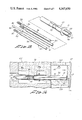
- FIG. 1 is a side elevation view of the crimping apparatus described herein.
- FIG. 2 is a top plan, elevational view of the apparatus of FIG. 1 showing the crimping and holding stations separated.
- FIG. 3 is a left end elevational view taken along the line 3--3 of FIG. 1.
- FIG. 4 is a right end elevational view taken along the line 4--4 of FIG. 1.
- FIG. 5 is a top plan view similar to FIG. 2 showing the crimping and holding stations closed on each other.
- FIG. 6 is a side elevational sectional view taken along the line 6--6 of FIG. 5.
- FIGS. 7, 8, 9 and 10 are end elevational, sectional views taken along the lines 7--7, 8--8, 9--9 and 10--10, respectively, of FIG. 6.
- FIG. 11 is a side elevational view of a jaw used in the crimping station.
- FIG. 12 is a further view of the crimping jaw of FIG. 11 taken at 90 degrees thereto.
- FIG. 13 is a jaw in the holding station.
- FIG. 14 is a further view of the holding jaw taken at 90 degrees to FIG. 13.
- FIG. 15 is an exploded view of an optical fiber, three fiber alignment rods and a connector part ferrule.
- FIG. 16 is a side elevational, sectional view of an optical fiber within the crimping station.
- FIG. 17 is a side elevational view of an alternate form of holding station.
- FIG. 18 is a top plan view, partially fragmentary, taken of the holding station of FIG. 17.
- FIG. 19 is an end elevational view taken along 19--19 of FIG. 17.
- FIG. 20 is an end elevational, sectional elevational view of the holding station of FIG. 17.
- FIG. 21 is a sectional, elevational view taken along the line 21--21 of FIG. 20.
- FIG. 22 is an end elevational view slightly enlarged showing three alignment pins being releasably held within retention jaws of the FIG. 17 holding station.
- FIG. 23 is an enlarged sectional, partially fragmentary view of a positioning means depicted in FIG. 21.
- a buffer-jacketed optical fiber 30 which is to be secured within a connector part in a manner to be described herein, includes a glass or plastic core and cladding 31, the cladding coaxially concentric with the core and an insulative protective coating or buffer jacketing 32.
- an optical signal entering at one end of the fiber core traverses the entire fiber length and exits at the other end to assimilation or processing equipment.
- the ends of these fibers must be faced off cleanly and precisely at 90 degrees to the fiber longitudinal axis, and the fibers must be precisely aligned with their end faces closely spaced but not contacting one another.
- Three identical alignment rods 33 are needed for each connector terminus, each one of which includes an end portion 34 having a plurality of circumferentially extending ridges, an immediately adjacent reduced diameter portion 35 and a smooth-surfaced cylindrical portion 36 of uniform diameter extending for a length slightly less than the bare fiber to be secured thereby.
- the three rods 33 are received about a fiber 30 with the peripheries of the cylindrical portions 36 contacting each other and the bare fiber, and the ridges 34 bitingly clamp into the fiber buffer-jacketing 32.
- the rods with included fiber are then slidingly positioned within a hollow metal tubular connector part or ferrule 37 in a way that will be described in detail herein.
- the connector part 37 is then deformed or crimped inwardly so as to clampingly engage the rods 33 and fiber 30 therewithin and positively position the fiber in a properly aligned relationship between the rods 33 with the outer end of the fiber being spaced slightly inwardly of the outer ends of the rods.
- Both fibers to be interconnected must be mounted in separate connector parts 37 and the two connector parts are received within an alignment sleeve (not shown) such that the outer end portions of both of the fibers with their retaining rods are located with the fibers very precisely aligned and the fiber end faces spaced from each other on the order of less than 0.001 of an inch.
- the crimping of the connector part 37 that is to be achieved with the present apparatus and in the manner described herein, is produced along a first set of longitudinally extending grooves 38, 39 and 40 that are located at both sides of a mounting and positioning upset 41.
- the apparatus also crimps a short section 42 of the connector part body which lies immediately opposite the ridges 34 of the rods 33 when they are properly located within the connector part, in order to drive the ridges into the cladding of the retained fiber, thereby securing the rods and fiber immovably at a predetermined location within the connector part.
- FIGS. 1 and 2 For the ensuing description of the apparatus for positively locating and securing the connector part 37 onto a set of three rods 33 with included optical fiber, reference is primarily made to FIGS. 1 and 2.
- An elongated base plate 43 having an upwardly directed, generally horizontal surface includes adjacent one end a holding station 44 mounted on the upper surface which accomplishes as its primary function retention and relative positioning of the three alignment rods 33 and included fiber while the connector part 37 is being fitted thereabout attendant securement in place.
- a crimping station 45 having selectively actuatable parts for applying a deforming force onto the exterior surface of the connector part or ferrule 37 is slidably mounted on a set of tracks 46 located on the upper surface of the base plate 43 to move along a path toward or away from the holding station. Also affixed to the upper surface of the base plate and extending upwardly therefrom is an optical fiber cable holding means 47 located along the axis of the path of movement of the crimping station 45.
- the optical fiber 30 has an end portion thereof stripped of its protective buffer-jacketing and an end face which is faced-off at precisely 90 degrees to the fiber axis, passed through oversize openings in the fiber cable holding means 47 and the crimping station 45 to terminate in the holding station 44 where it is releasably held within three locating pins 33 in a manner already described.
- An uncrimped ferrule or connector part 37 initially loosely received onto the bare or stripped fiber is slid over and onto the holding pins and properly located thereon after which the crimping station is moved along its track in order to locate pressure exerting jaws over the ferrule. These jaws then crimp the connector part ferrule onto the rods and included fiber. Finally, the crimping jaws, holding station and fiber holding means are all released and the crimped fiber optic terminus assembly is removed from the apparatus.
- the holding station 44 includes an upright stanchion 48 suitably affixed to the upper surface of the base plate 43 and through which an opening 49 is formed closely adjacent its upper extremity.
- a head portion 50 has a threaded shaft 51 received through the opening 49 and onto which a nut 52 is secured.
- the head portion is cylindrical with an axial opening extending therethrough including an enlarged diameter part 53 serving as the exit and a smaller diameter part 54 forming the entrance.
- a cylindrical metal pin 55 with a pointed end has an outer diameter sufficient so that it may be snugly received within the opening 54 with the pointed end facing toward the crimping station.
- a threaded member 56 fixes the pin within the opening.
- three chuck jaws 57-59 arranged at 120 degrees with respect to each other are radially adjustable toward and away from an axis which is an extension of and collinear with the axis of openings 53 and 54.
- the chuck jaws are slidingly received within suitably formed openings in a cylindrical body member 60 which is integral with the head portion 50 and extends toward the crimping station.
- a face plate 61 (FIG. 9) is received over the outwardly facing end of 60 and secured thereto by threaded means 62.
- An opening 63 in the face plate is collinear with the axis of openings 53 and 54 and of a sufficient diameter to readily permit the leading end of the ferrule connector part 37 to pass therethrough.
- a coupling ring 64 has a threaded opening for receipt upon a similarly threaded periphery of the head 50 and a tapered inwardly directed wall 65 for contacting a similarly tapered periphery of the chuck jaws 57-59.
- adjustment of the coupling ring 64 moves the jaws 57-59 inwardly towards each other.
- a plurality of springs 66 interrelate the inner end portions of the jaws 57-59 such that when the coupling ring is adjusted to release the jaws, the springs will automatically move them apart.
- the inner end surfaces of the jaws are formed into axially extending cylindrical grooves in order that they may fittingly grip a set of three rods 33 and included fiber therewithin in the respective grooves.
- a viewing port slot 67 (FIGS. 2 and 6) for observation of fiber/rods relative position extends circumferentially through the wall of the coupling ring 64 allowing verification of correct component juxtaposition.
- a limit stop 67b spacer fills the thread relief void to prevent tightening the coupling ring beyond a predetermined maximum and applying undue force to the rods 33 either damaging them and/or the included fiber.
- the bare end of the fiber with a set of three rods 33 about it are inserted through the opening 63 of the face plate 61 and are moved forwardly until the pointed end of the pin 55 extends very slightly into the interstice between. the rods thereby precisely locating the outermost end of the bare fiber.
- the coupling ring is then rotated in the direction to clamp the rods and fiber securely, but not so tightly as to harm either the fiber or alignment rods.
- the coupling ring is then rotated in the opposite direction to release the crimped three rod/fiber assembly.
- the crimping station identified generally as 45 includes a generally L-shaped mounting bracket 68, the lower arm of which is mounted onto a runner 69 which is slidingly received in a groove in the track 46 (FIGS. 1, 3 and 4). That is, the bracket 68 and the equipment carried thereby may be moved along the track toward or away from the holding station 44, as desired.
- the crimping station is seen to further include an elongated generally cylindrical body 70 having a reduced diameter threaded end received through an unthreaded opening 71 in the upstanding portion of the L-shaped mounted bracket 68.
- a nut 72 threaded onto the reduced diameter end secures the body 70 extending generally parallel to the base plate toward the holding station.
- An axial opening 73 in the body 70 extends completely therethrough and is of a diameter sufficient to permit ready passage of the ferrule 37 therealong.
- the body 70 outermost end portion identified generally as at 74 is cylindrical with a smooth periphery and includes three longitudinally extending slots 75 arranged at 120 degrees to one another and communicating with a passageway extending along the axis of 74 (FIGS. 7 and 8). Within the slots 75, there are arranged crimping jaws 76, 77 and 78, respectively, the outer surfaces of which are longitudinally tapered increasing from a minimum at the end of 74 on moving toward the bracket 68 (FIG. 6).
- a hollow cylindrical shell-like member 79 serves as a coupling ring and has a tapered surface 80 for coacting with the jaws 76-78 to adjust them radially inwardly or outwardly in accordance with the direction of rotation of the coupling ring.
- Threads 81 on the inner surface of the coupling ring mesh with threads 82 on the periphery of the body 70 via which adjustment of the coupling ring is produced.
- Springs 83 have their ends received within opposing recesses in the jaws 76-78 providing a force to automatically move the jaws apart upon release of contact between the coupling ring and the tapered outer jaws surfaces (FIG. 7).
- the crimping jaws 76-78 each have a specifically contoured inner surface 84 which, when it is moved against the side of the connector ferrule 37, will bear against those parts of the ferrule that it is desired to deform or crimp.
- a specifically contoured inner surface 84 which, when it is moved against the side of the connector ferrule 37, will bear against those parts of the ferrule that it is desired to deform or crimp.
- knife-like edges on the jaws are provided.
- indented or deeply grooved regions such as 85 and 86 are located.
- the optical fiber cable holding means 47 shown in FIG. 3 includes an upstanding wall member 87 having its lower end resting on the top of the base plate 43 and affixed to the end of the track 46 by threaded members 88.
- a floating gripper plate 89 is interrelated to the upper surface of the wall 87 by a pair of threaded means 90 having smooth shank portions slidingly received within openings in the plate 89 and compression springs 91 urging the head of each of the threaded means 90 upwardly away from the plate 87.
- the plate 89 is resiliently urged downwardly and substantially into contact with the upper surface of the wall 87, but can be moved upwardly against the pressure of the springs to a spaced relation, if so desired.
- Matching semi-cylindrical grooves in the facing surfaces of the wall 87 and plate 89 form a cylindrical opening 92 of dimensions substantially the same as that of an optic fiber cable.
- An adjustable retention knob 93 is fitted within a threaded opening in the gripper plate 89 and has an inner end which, depending upon the adjustment of 93, can extend into the opening 92 for bearing against an optic fiber cable located in the opening.
- a jacketed optical fiber cable 30 with an extended length of its buffer-jacketing material removed leaving a bare fiber 31 is inserted through the opening 92 in the fiber cable holding means 47, through the central passageway 73 of the crimping station and outwardly through the crimping jaws central opening (assuming the coupling ring 79 is adjusted to the open position) and an uncrimped ferrule or connector part 37 is located on the bare fiber somewhat as shown in FIG. 1, for example.
- a set of three rods 33 are inserted within the jaws 57-59 and the jaws are tightened down snugly.
- the bare fiber is then inserted into the interstice formed by the three rods 33 with the locating pin 55 holding the cleaved fiber end at the proper distance from the outer end faces of the rods.
- the knob 93 (FIG. 3) is adjusted to clampingly engage the fiber and hold it substantially horizontally within the entire apparatus.
- the ferrule 37 is slid along the bare fiber from the position shown in FIG. 1 to a position in which it is received over the rods 33 (FIG. 6) and against the stop provided by jaws 57-59.
- the crimping station 45 is moved along the track 46 toward the holding station 44 until the jaws 76-78 are located with the various contoured gripping surfaces 84 lying immediately opposite the corresponding parts on the ferrule. Proper positioning is achieved when the outermost ends of the jaws 76-78 abut directly against the face plate 61 on the holding station chuck.
- Arms 94 are then rotated which, in turn, rotate the coupling ring 79 to move the jaws inwardly and deform the connector part ferrule 37 about the rods 33.
- the connector part 37 is secured about the rods and fiber with the fiber located in properly spaced relation within the rods.
- the crimping jaws are loosened, the crimping station is moved away from the finally secured ferrule, the jaws of the holding station are released and the knob 93 of the fiber holding means is loosened permitting the entire optical fiber with connector part in place to be removed from the apparatus.
- FIGS. 17-23 For the ensuing description of an alternate form of holding station reference is now made to FIGS. 17-23. It is to be understood that the holding station to be described at this time interacts with the fiber holding means 47 and crimping station 45 as already described.
- the alternate form of holding station is identified in FIG. 17 as at 95 and comprises an upstanding wall plate 96 having its lower end resting on base plate 43 and affixed to the outer end of track 46 by threaded members 97.
- the upper surface of plate 96 includes a centrally located rectangular portion 98 having a V-shaped notch 99.
- the notch is precisely formed such that when three alignment rods 33 are located therein they will each contact the others along longitudinal peripheral lines, and the upper two rods will extend slightly above the uppermost surface of rectangular portion 98 (FIG. 22).
- a cap plate 100 is generally rectangular and includes a central notch permitting sliding and fitting receipt onto the rectangular portion 98 and the remaining top wall of 96.
- First and second shafts 101 are located with their heads slidingly received within respective openings 103 in the cap plate.
- the shafts extend downwardly and slidingly through further openings 104 in the cap plate and have their end portions secured within openings 105 in the top surface of plate 96 by set screws 106.
- a cavity 107 in the side of plate 96 encloses a transfer block 108 to which are affixed first and second drive rods 109 and 110 that extend through respective openings 111 and 112 in plate 96.
- An eccentrically mounted roller cam 113 has its peripheral camming surface in continual engagement with a follower pin 114 in the transfer block which can move the drive rods 109-110 from their lowermost position where cap plate 100 rests on plate 96 to an uppermost position where the two plates are held spaced apart.
- a manually adjustable knob 115 is journaled within plate 96 with its inner end connected to eccentric roller cam 113, by which means the cam may be adjusted and the cap plate raised or lowered, depending on the knob adjustment.
- a housing 116 affixed to the outer end surface of the plates 96 and 100 by screws 117 includes a hardened plate 118 located therebetween.
- An opening 119 in housing 116 is collinear with the interstice axis between rods 33 located in notch 99.
- An opening 120 in plate 118 is aligned with opening 119 and has a tapered inner entrance portion.
- a precision ball 121 is resiliently urged by a compression coil spring 122 into the opening in plate 118 and the relative dimensions are such that a portion of the ball 121 extends outwardly of plate 118 and within the interstice of three rods 33 contacting the plate (e.g., 0.0005 inches) to position the fiber end accordingly.
- the fiber with ferrule 37 is inserted through the fiber cable holding means and crimping station as described in regard to the first embodiment.
- Knob 115 is turned to separate the cap plate 100 from the upstanding plate 96, and a set of three rods 33 are located within the notch and moved into contact with hardened plate 118.
- the bare fiber is inserted into the interstice formed by the three rods 33 and stops against the ball 121 locating the fiber end inwardly of the rod ends a slight amount.
- the knob 115 is then adjusted to close the cap plate onto plate 96 and the remainder of the operation is as was previously described.
Abstract
Description
Claims (9)
Priority Applications (4)
| Application Number | Priority Date | Filing Date | Title |
|---|---|---|---|
| US06/598,170 US4567650A (en) | 1984-04-09 | 1984-04-09 | Fiber optic crimping tool |
| NO850364A NO850364L (en) | 1984-04-09 | 1985-01-30 | FIBEROPTIC SHRINKLE TOOL. |
| EP85300763A EP0159768A3 (en) | 1984-04-09 | 1985-02-05 | Fiber optic crimping tool |
| JP60055623A JPS613108A (en) | 1984-04-09 | 1985-03-19 | Climper for optical fiber |
Applications Claiming Priority (1)
| Application Number | Priority Date | Filing Date | Title |
|---|---|---|---|
| US06/598,170 US4567650A (en) | 1984-04-09 | 1984-04-09 | Fiber optic crimping tool |
Publications (1)
| Publication Number | Publication Date |
|---|---|
| US4567650A true US4567650A (en) | 1986-02-04 |
Family
ID=24394525
Family Applications (1)
| Application Number | Title | Priority Date | Filing Date |
|---|---|---|---|
| US06/598,170 Expired - Lifetime US4567650A (en) | 1984-04-09 | 1984-04-09 | Fiber optic crimping tool |
Country Status (4)
| Country | Link |
|---|---|
| US (1) | US4567650A (en) |
| EP (1) | EP0159768A3 (en) |
| JP (1) | JPS613108A (en) |
| NO (1) | NO850364L (en) |
Cited By (34)
| Publication number | Priority date | Publication date | Assignee | Title |
|---|---|---|---|---|
| US4707072A (en) * | 1984-12-18 | 1987-11-17 | U.S. Philips Corp. | Auto-aligning optical fiber connector |
| US4894111A (en) * | 1983-03-25 | 1990-01-16 | Siemens Aktiengesellschaft | Plug part for releasable plug-type connections of eight waveguide |
| US4907335A (en) * | 1988-06-20 | 1990-03-13 | Amp Incorporated | Tool for assembling optical fiber |
| US5046350A (en) * | 1989-11-03 | 1991-09-10 | United States Surgical Corporation | Apparatus for attaching surgical suture components |
| US5099676A (en) * | 1989-11-03 | 1992-03-31 | United States Surgical Corporation | Apparatus for attaching surgical suture components |
| US5131131A (en) * | 1989-11-03 | 1992-07-21 | United States Surgical Corporation | Method for attaching surgical suture components |
| US5168619A (en) * | 1989-11-03 | 1992-12-08 | United States Surgical Corporation | Method for attaching surgical suture components |
| US5243673A (en) * | 1989-08-02 | 1993-09-07 | E. I. Du Pont De Nemours And Company | Opto-electronic component having positioned optical fiber associated therewith |
| US5307432A (en) * | 1992-10-09 | 1994-04-26 | Luxtec Corporation | Crimped light source terminations |
| US5350373A (en) * | 1992-10-09 | 1994-09-27 | United States Surgical Corporation | Apparatus for attaching surgical suture components |
| US5383902A (en) * | 1993-06-02 | 1995-01-24 | United States Surgical Corporation | Surgical needle-suture attachment for controlled suture release |
| US5394606A (en) * | 1991-07-15 | 1995-03-07 | The Furukawa Electric Co., Ltd. | Apparatus for assembly and inspection of optical fiber connectors |
| US5394971A (en) * | 1993-08-02 | 1995-03-07 | United States Surgical Corporation | Apparatus for attaching surgical suture components |
| US5707391A (en) * | 1995-06-07 | 1998-01-13 | United States Surgical Corporation | Apparatus and method for attaching surgical needle suture components |
| US5722991A (en) * | 1995-06-07 | 1998-03-03 | United States Surgical Corporation | Apparatus and method for attaching surgical needle suture components |
| US5787572A (en) * | 1995-02-14 | 1998-08-04 | Schott Fibre Optics (Uk) Limited | Apparatus for terminating a fibre optic bundle |
| WO1998036304A1 (en) * | 1997-02-18 | 1998-08-20 | Amphenol Corporation | Adhesiveless fiber optic connector and an apparatus for terminating fiber optic cable to an adhesiveless connector |
| US6016682A (en) * | 1998-08-11 | 2000-01-25 | Ethicon, Inc. | Swaging apparatus for surgical needles |
| US6044547A (en) * | 1998-07-20 | 2000-04-04 | Veriflo Corporation | Integrated crimp bias apparatus |
| US6240615B1 (en) * | 1998-05-05 | 2001-06-05 | Advanced Cardiovascular Systems, Inc. | Method and apparatus for uniformly crimping a stent onto a catheter |
| WO2002011961A1 (en) * | 2000-08-09 | 2002-02-14 | Chiral Photonics, Inc. | Apparatus and method for manufacturing fiber gratings |
| US6510722B1 (en) * | 2000-05-10 | 2003-01-28 | Advanced Cardiovascular Systems, Inc. | Stent crimping tool for producing a grooved crimp |
| US20040096538A1 (en) * | 2002-08-16 | 2004-05-20 | Edward Goff | Swaging technology |
| US20040194528A1 (en) * | 1994-12-30 | 2004-10-07 | Black & Decker, Inc. | Method and apparatus for forming parts from a continuous stock material and associated forge |
| WO2005040877A1 (en) * | 2003-09-23 | 2005-05-06 | Schäfer Werkzeug- und Sondermaschinenbau GmbH | Device for fixing the end of a columnar body in a passage of a connector running parallel to the axis thereof |
| US20050166389A1 (en) * | 2004-01-29 | 2005-08-04 | Scimed Life Systems, Inc. | Apparatuses for crimping and loading of intraluminal medical devices |
| US20050234537A1 (en) * | 2004-04-16 | 2005-10-20 | Scimed Life Systems, Inc. | Stent crimper |
| US20050229670A1 (en) * | 2004-04-16 | 2005-10-20 | Scimed Life Systems, Inc. | Stent crimper |
| US20050276554A1 (en) * | 2004-06-12 | 2005-12-15 | Hubertus Russert | Apparatus and method for producing an end of an optical fiber bundle and improved optical fiber bundle made with same |
| US20060004469A1 (en) * | 2004-06-16 | 2006-01-05 | Justin Sokel | Tissue prosthesis processing technology |
| WO2006111160A1 (en) * | 2005-04-22 | 2006-10-26 | Michael Weber | Device for intravenous blood laser radiation and method for producing a disposable catheter designed for a device |
| US20070286563A1 (en) * | 2006-06-13 | 2007-12-13 | Panduit Corp. | Activation tool for a fiber optic connector |
| US20100054669A1 (en) * | 2008-09-04 | 2010-03-04 | Dimarco Brian Anthony | Fiber optic connector |
| US20150094539A1 (en) * | 2013-09-27 | 2015-04-02 | Peter Eisenkolb | Producing of an endoscope with an optical waveguide |
Families Citing this family (2)
| Publication number | Priority date | Publication date | Assignee | Title |
|---|---|---|---|---|
| CA1306375C (en) * | 1986-05-06 | 1992-08-18 | Robert Schlingensiepen | Block for optical termination |
| US9239428B2 (en) | 2011-09-28 | 2016-01-19 | Ksaria Corporation | Epoxy dispensing system and dispensing tip used therewith |
Citations (14)
| Publication number | Priority date | Publication date | Assignee | Title |
|---|---|---|---|---|
| US1435035A (en) * | 1921-08-30 | 1922-11-07 | Adolph A Walroden | Double-motion cam device |
| US1533875A (en) * | 1924-09-17 | 1925-04-14 | Mccleary Clyde | Casing-head latch |
| US1565227A (en) * | 1920-10-26 | 1925-12-08 | Garrison Orlando | Chuck |
| US2377829A (en) * | 1943-07-26 | 1945-06-05 | John L Vaill | Automatic ferrule attaching machine |
| US2688133A (en) * | 1950-12-29 | 1954-09-07 | Aircraft Marine Prod Inc | Applicator for connectors and the like |
| US3028776A (en) * | 1959-06-04 | 1962-04-10 | Bendix Corp | Crimping tool with adjusting means |
| US3451116A (en) * | 1966-09-27 | 1969-06-24 | Walter A Shields | Machine for crimping a ferrule to a hypodermic needle |
| US3789485A (en) * | 1973-01-24 | 1974-02-05 | Artos Engineering Co | Method and apparatus for producing flexible fiber optical light conductors |
| US4019241A (en) * | 1975-11-10 | 1977-04-26 | Thomas & Betts Corporation | Method of splicing elongate members |
| FR2417122A1 (en) * | 1978-02-14 | 1979-09-07 | Thomson Csf | Sleeve fixing machine for fibre optic cables - has hinged hexagonal section defining cable cross=section, with securing guide plates |
| US4217084A (en) * | 1977-11-28 | 1980-08-12 | Socapex | Device for crimping ferrules onto bundles of optical fibres |
| JPS57125914A (en) * | 1981-01-30 | 1982-08-05 | Nippon Telegr & Teleph Corp <Ntt> | Optical fiber connector |
| US4469400A (en) * | 1981-06-24 | 1984-09-04 | Compagnie Lyonnaise De Transmissions Optiques | Connector for a single optical fiber |
| US4486072A (en) * | 1982-01-12 | 1984-12-04 | Augat Inc. | Optical connector and splicing device using double diameter resilient rods |
Family Cites Families (6)
| Publication number | Priority date | Publication date | Assignee | Title |
|---|---|---|---|---|
| NL146986B (en) * | 1967-10-30 | 1975-08-15 | Amp Inc | DEVICE FOR PREPARING AN END PART OF A COAXIAL CABLE FOR CONNECTION TO A COAXIAL CONNECTOR. |
| FR2440005A1 (en) * | 1978-10-27 | 1980-05-23 | Socapex | CONNECTOR TIP FOR OPTICAL MONOFIBER, AND METHOD FOR FIXING SUCH A TIP ON SUCH A MONOFIBER |
| DE2943180C2 (en) * | 1979-10-25 | 1986-04-24 | Bunker Ramo Corp., Oak Brook, Ill. | Fiber optic connector |
| BR8103627A (en) * | 1980-06-12 | 1982-03-02 | Du Pont | OPTICAL FIBER CONNECTOR |
| US4483584A (en) * | 1981-09-28 | 1984-11-20 | Automation Industries, Inc. | Optical fiber connector |
| CA1240184A (en) * | 1982-05-24 | 1988-08-09 | Amp Inc | Connector for fiber optic member |
-
1984
- 1984-04-09 US US06/598,170 patent/US4567650A/en not_active Expired - Lifetime
-
1985
- 1985-01-30 NO NO850364A patent/NO850364L/en unknown
- 1985-02-05 EP EP85300763A patent/EP0159768A3/en not_active Withdrawn
- 1985-03-19 JP JP60055623A patent/JPS613108A/en active Pending
Patent Citations (14)
| Publication number | Priority date | Publication date | Assignee | Title |
|---|---|---|---|---|
| US1565227A (en) * | 1920-10-26 | 1925-12-08 | Garrison Orlando | Chuck |
| US1435035A (en) * | 1921-08-30 | 1922-11-07 | Adolph A Walroden | Double-motion cam device |
| US1533875A (en) * | 1924-09-17 | 1925-04-14 | Mccleary Clyde | Casing-head latch |
| US2377829A (en) * | 1943-07-26 | 1945-06-05 | John L Vaill | Automatic ferrule attaching machine |
| US2688133A (en) * | 1950-12-29 | 1954-09-07 | Aircraft Marine Prod Inc | Applicator for connectors and the like |
| US3028776A (en) * | 1959-06-04 | 1962-04-10 | Bendix Corp | Crimping tool with adjusting means |
| US3451116A (en) * | 1966-09-27 | 1969-06-24 | Walter A Shields | Machine for crimping a ferrule to a hypodermic needle |
| US3789485A (en) * | 1973-01-24 | 1974-02-05 | Artos Engineering Co | Method and apparatus for producing flexible fiber optical light conductors |
| US4019241A (en) * | 1975-11-10 | 1977-04-26 | Thomas & Betts Corporation | Method of splicing elongate members |
| US4217084A (en) * | 1977-11-28 | 1980-08-12 | Socapex | Device for crimping ferrules onto bundles of optical fibres |
| FR2417122A1 (en) * | 1978-02-14 | 1979-09-07 | Thomson Csf | Sleeve fixing machine for fibre optic cables - has hinged hexagonal section defining cable cross=section, with securing guide plates |
| JPS57125914A (en) * | 1981-01-30 | 1982-08-05 | Nippon Telegr & Teleph Corp <Ntt> | Optical fiber connector |
| US4469400A (en) * | 1981-06-24 | 1984-09-04 | Compagnie Lyonnaise De Transmissions Optiques | Connector for a single optical fiber |
| US4486072A (en) * | 1982-01-12 | 1984-12-04 | Augat Inc. | Optical connector and splicing device using double diameter resilient rods |
Cited By (67)
| Publication number | Priority date | Publication date | Assignee | Title |
|---|---|---|---|---|
| US4894111A (en) * | 1983-03-25 | 1990-01-16 | Siemens Aktiengesellschaft | Plug part for releasable plug-type connections of eight waveguide |
| US4707072A (en) * | 1984-12-18 | 1987-11-17 | U.S. Philips Corp. | Auto-aligning optical fiber connector |
| US4907335A (en) * | 1988-06-20 | 1990-03-13 | Amp Incorporated | Tool for assembling optical fiber |
| AU626862B2 (en) * | 1988-06-20 | 1992-08-13 | Amp Incorporated | Applying pressure to abutting optical faces |
| US5243673A (en) * | 1989-08-02 | 1993-09-07 | E. I. Du Pont De Nemours And Company | Opto-electronic component having positioned optical fiber associated therewith |
| US5046350A (en) * | 1989-11-03 | 1991-09-10 | United States Surgical Corporation | Apparatus for attaching surgical suture components |
| US5099676A (en) * | 1989-11-03 | 1992-03-31 | United States Surgical Corporation | Apparatus for attaching surgical suture components |
| US5131131A (en) * | 1989-11-03 | 1992-07-21 | United States Surgical Corporation | Method for attaching surgical suture components |
| US5168619A (en) * | 1989-11-03 | 1992-12-08 | United States Surgical Corporation | Method for attaching surgical suture components |
| US5394606A (en) * | 1991-07-15 | 1995-03-07 | The Furukawa Electric Co., Ltd. | Apparatus for assembly and inspection of optical fiber connectors |
| US5608962A (en) * | 1992-10-09 | 1997-03-11 | United States Surgical Corporation | Method and apparatus for attaching surgical suture components |
| US5307432A (en) * | 1992-10-09 | 1994-04-26 | Luxtec Corporation | Crimped light source terminations |
| US5350373A (en) * | 1992-10-09 | 1994-09-27 | United States Surgical Corporation | Apparatus for attaching surgical suture components |
| US5462543A (en) * | 1992-10-09 | 1995-10-31 | United States Surgical Corporation | Apparatus for attaching surgical suture components |
| US5568746A (en) * | 1993-06-02 | 1996-10-29 | United States Surgical Corporation | Surgical needle-suture attachment for controlled suture release |
| US5383902A (en) * | 1993-06-02 | 1995-01-24 | United States Surgical Corporation | Surgical needle-suture attachment for controlled suture release |
| US5394971A (en) * | 1993-08-02 | 1995-03-07 | United States Surgical Corporation | Apparatus for attaching surgical suture components |
| US7127923B2 (en) * | 1994-12-30 | 2006-10-31 | Black & Decker, Inc. | Method and apparatus for forming parts from a continuous stock material and associated forge |
| US20040194528A1 (en) * | 1994-12-30 | 2004-10-07 | Black & Decker, Inc. | Method and apparatus for forming parts from a continuous stock material and associated forge |
| US5787572A (en) * | 1995-02-14 | 1998-08-04 | Schott Fibre Optics (Uk) Limited | Apparatus for terminating a fibre optic bundle |
| US5707391A (en) * | 1995-06-07 | 1998-01-13 | United States Surgical Corporation | Apparatus and method for attaching surgical needle suture components |
| US5722991A (en) * | 1995-06-07 | 1998-03-03 | United States Surgical Corporation | Apparatus and method for attaching surgical needle suture components |
| US5862289A (en) * | 1997-02-18 | 1999-01-19 | Amphenol Corporation | Adhesiveless fiber optic connector, and an apparatus and method for terminating a fiber optic cable to an adhesiveless fiber optic connector |
| US5943460A (en) * | 1997-02-18 | 1999-08-24 | Amphenol Corporation | Adhesiveless fiber optic connector, and an apparatus and method for terminating a fiber optic cable to an adhesiveless fiber optic connector |
| WO1998036304A1 (en) * | 1997-02-18 | 1998-08-20 | Amphenol Corporation | Adhesiveless fiber optic connector and an apparatus for terminating fiber optic cable to an adhesiveless connector |
| US6240615B1 (en) * | 1998-05-05 | 2001-06-05 | Advanced Cardiovascular Systems, Inc. | Method and apparatus for uniformly crimping a stent onto a catheter |
| US6314635B1 (en) | 1998-07-20 | 2001-11-13 | Veriflo Corporation | Integrated crimp bias apparatus and method |
| US6044547A (en) * | 1998-07-20 | 2000-04-04 | Veriflo Corporation | Integrated crimp bias apparatus |
| US6016682A (en) * | 1998-08-11 | 2000-01-25 | Ethicon, Inc. | Swaging apparatus for surgical needles |
| US6510722B1 (en) * | 2000-05-10 | 2003-01-28 | Advanced Cardiovascular Systems, Inc. | Stent crimping tool for producing a grooved crimp |
| WO2002011961A1 (en) * | 2000-08-09 | 2002-02-14 | Chiral Photonics, Inc. | Apparatus and method for manufacturing fiber gratings |
| US20040096538A1 (en) * | 2002-08-16 | 2004-05-20 | Edward Goff | Swaging technology |
| JP2005535459A (en) * | 2002-08-16 | 2005-11-24 | マシーン ソリューションズ インコーポレイテッド | Upset technology |
| US6931899B2 (en) * | 2002-08-16 | 2005-08-23 | Machine Solutions, Inc. | Swaging technology |
| WO2005040877A1 (en) * | 2003-09-23 | 2005-05-06 | Schäfer Werkzeug- und Sondermaschinenbau GmbH | Device for fixing the end of a columnar body in a passage of a connector running parallel to the axis thereof |
| US7316147B2 (en) | 2004-01-29 | 2008-01-08 | Boston Scientific Scimed, Inc. | Apparatuses for crimping and loading of intraluminal medical devices |
| US8438895B2 (en) | 2004-01-29 | 2013-05-14 | Boston Scientific Scimed, Inc. | Apparatuses for crimping and loading of intraluminal medical devices |
| US20110162432A1 (en) * | 2004-01-29 | 2011-07-07 | Boston Scientific Scimed, Inc. | Apparatuses for crimping and loading of intraluminal medical devices |
| US7926320B2 (en) | 2004-01-29 | 2011-04-19 | Boston Scientific Scimed, Inc. | Apparatuses for crimping and loading of intraluminal medical devices |
| US20100095513A1 (en) * | 2004-01-29 | 2010-04-22 | Boston Scientific Scimed, Inc. | Apparatuses for crimping and loading of intraluminal medical devices |
| US7636997B2 (en) | 2004-01-29 | 2009-12-29 | Boston Scientific Scimed, Inc. | Method for crimping and loading of intraluminal medical devices |
| US20080173061A1 (en) * | 2004-01-29 | 2008-07-24 | Boston Scientific Scimed, Inc. | Apparatuses for crimping and loading of intraluminal medical devices |
| US20050166389A1 (en) * | 2004-01-29 | 2005-08-04 | Scimed Life Systems, Inc. | Apparatuses for crimping and loading of intraluminal medical devices |
| US7143625B2 (en) | 2004-04-16 | 2006-12-05 | Boston Scientific Scimed, Inc. | Stent crimper |
| US7021114B2 (en) | 2004-04-16 | 2006-04-04 | Boston Scientific Scimed, Inc. | Stent crimper |
| US20050234537A1 (en) * | 2004-04-16 | 2005-10-20 | Scimed Life Systems, Inc. | Stent crimper |
| US20050229670A1 (en) * | 2004-04-16 | 2005-10-20 | Scimed Life Systems, Inc. | Stent crimper |
| EP1607776A1 (en) * | 2004-06-12 | 2005-12-21 | Schott AG | Method for making a termination of an optical fibre bundle, corresponding press tool and optical fibre bundle |
| US7958753B2 (en) | 2004-06-12 | 2011-06-14 | Schott Ag | Apparatus and method for producing an end of an optical fiber bundle and improved optical fiber bundle made with same |
| US20050276554A1 (en) * | 2004-06-12 | 2005-12-15 | Hubertus Russert | Apparatus and method for producing an end of an optical fiber bundle and improved optical fiber bundle made with same |
| US7457499B2 (en) | 2004-06-12 | 2008-11-25 | Schott Ag | Apparatus and method for producing an end of an optical fiber bundle and improved optical fiber bundle made with same |
| CN100437175C (en) * | 2004-06-12 | 2008-11-26 | 肖特股份有限公司 | Method for making a termination of an optical fibre bundle and corresponding press tool |
| US20060004469A1 (en) * | 2004-06-16 | 2006-01-05 | Justin Sokel | Tissue prosthesis processing technology |
| US7415861B2 (en) * | 2004-06-16 | 2008-08-26 | Machine Solutions, Inc. | Tissue prosthesis processing technology |
| US8776352B2 (en) | 2004-06-16 | 2014-07-15 | Machine Solutions, Inc. | Tissue prosthesis processing technology |
| WO2006007401A3 (en) * | 2004-06-16 | 2008-01-03 | Mach Solutions Inc | Tissue prothesis processing technology |
| US8312614B2 (en) | 2004-06-16 | 2012-11-20 | Machine Solutions, Inc. | Tissue prosthesis processing technology |
| WO2006111160A1 (en) * | 2005-04-22 | 2006-10-26 | Michael Weber | Device for intravenous blood laser radiation and method for producing a disposable catheter designed for a device |
| US20070286563A1 (en) * | 2006-06-13 | 2007-12-13 | Panduit Corp. | Activation tool for a fiber optic connector |
| US7639917B2 (en) | 2006-06-13 | 2009-12-29 | Panduit Corp. | Activation tool for a fiber optic connector |
| US7466891B2 (en) | 2006-06-13 | 2008-12-16 | Panduit Corp. | Activation tool for a fiber optic connector |
| US20100129044A1 (en) * | 2006-06-13 | 2010-05-27 | Panduit Corp. | Activation Tool for a Fiber Optic Connector |
| US8005336B2 (en) | 2006-06-13 | 2011-08-23 | Panduit Corp. | Activation tool for a fiber optic connector |
| US20080118206A1 (en) * | 2006-06-13 | 2008-05-22 | Panduit Corp. | Activation Tool for a Fiber Optic Connector |
| US7712973B2 (en) * | 2008-09-04 | 2010-05-11 | Fibersource, Inc. | Fiber optic connector |
| US20100054669A1 (en) * | 2008-09-04 | 2010-03-04 | Dimarco Brian Anthony | Fiber optic connector |
| US20150094539A1 (en) * | 2013-09-27 | 2015-04-02 | Peter Eisenkolb | Producing of an endoscope with an optical waveguide |
Also Published As
| Publication number | Publication date |
|---|---|
| NO850364L (en) | 1985-10-10 |
| EP0159768A3 (en) | 1988-01-13 |
| EP0159768A2 (en) | 1985-10-30 |
| JPS613108A (en) | 1986-01-09 |
Similar Documents
| Publication | Publication Date | Title |
|---|---|---|
| US4567650A (en) | Fiber optic crimping tool | |
| EP0159198B1 (en) | Optical fiber termination, process of terminating an optical fiber, and apparatus for terminating an optical fiber. | |
| US4127319A (en) | Termination means for fiber optic bundle | |
| US5469522A (en) | Optical fiber splice interconnection and usage method | |
| US4239333A (en) | Non-twist eccentric coupler | |
| US4181401A (en) | Fiber optic waveguide connector | |
| US3972585A (en) | Connectors for optical fibers | |
| EP0026553A1 (en) | Self-aligning optical fiber connector | |
| US4483584A (en) | Optical fiber connector | |
| US4309071A (en) | Connector for optical fibers and device for mounting fibers on tips directly usable on connectors | |
| AU658062B2 (en) | An optical fiber three-rod connector having a rod-securing clip | |
| US20070217745A1 (en) | Mechanical splice connector with sequential splice and strain relief | |
| US4204306A (en) | Apparatus for aligning and terminating an optical fiber within a fiber optic connector | |
| US5140661A (en) | Optical fiber terminus | |
| US4217084A (en) | Device for crimping ferrules onto bundles of optical fibres | |
| US20100303418A1 (en) | Fiber guiding platform for mechanical splicer, optical connectors, fiber holder and methods | |
| EP0105909A1 (en) | Precision cleaving of optical fibers. | |
| KR20150043297A (en) | Optical fiber cleaving mechanism and method of use | |
| US4968109A (en) | Press bonding apparatus method for terminating an optical fiber with a plastically deformable termination member | |
| JPS61258205A (en) | Optical fiber bending device | |
| US5574813A (en) | Optical fiber connector, abutment fixture and method of compatible use thereof | |
| US5556502A (en) | Optical fiber cable chemical stripping fixture | |
| AU626862B2 (en) | Applying pressure to abutting optical faces | |
| US5067226A (en) | Method of assembling an optical fiber by applying pressure to abutting optical faces | |
| US4459746A (en) | Tool for cleaning the exposed end of an optical fiber |
Legal Events
| Date | Code | Title | Description |
|---|---|---|---|
| AS | Assignment |
Owner name: AUTOMATION INDUSTRIES, INC., 500 WEST PUTNAM AVENU Free format text: ASSIGNMENT OF ASSIGNORS INTEREST.;ASSIGNORS:BALYASNY, MARIK;PARKER, DOUGLAS A.;REEL/FRAME:004247/0875 Effective date: 19840229 |
|
| STCF | Information on status: patent grant |
Free format text: PATENTED CASE |
|
| AS | Assignment |
Owner name: G&H TECHNIOLOGY, INC., 1649 - 17TH STREET, SANTA M Free format text: ASSIGNMENT OF ASSIGNORS INTEREST.;ASSIGNORS:AUTOMATION INDUSTRIES, INC., FORMERLY PCC;TECHNICAL INDUSTRIES, INC., A CORP. OF CA.;REEL/FRAME:004513/0924 Effective date: 19860114 |
|
| FPAY | Fee payment |
Year of fee payment: 4 |
|
| FEPP | Fee payment procedure |
Free format text: PAYOR NUMBER ASSIGNED (ORIGINAL EVENT CODE: ASPN); ENTITY STATUS OF PATENT OWNER: LARGE ENTITY |
|
| FPAY | Fee payment |
Year of fee payment: 8 |
|
| FPAY | Fee payment |
Year of fee payment: 12 |
|
| AS | Assignment |
Owner name: GHAC, INC., CALIFORNIA Free format text: ASSIGNMENT OF ASSIGNORS INTEREST;ASSIGNOR:BANK AUSTRIA CREDITANSTALT FINANCE, INC.;REEL/FRAME:012391/0123 Effective date: 20011030 |
|
| AS | Assignment |
Owner name: BANK AUSTRIA CREDITANSTALT FINANCE, INC., NEW YORK Free format text: ASSIGNMENT OF ASSIGNORS INTEREST;ASSIGNOR:G&H TECHNOLOGY, INC.;REEL/FRAME:012418/0096 Effective date: 19941207 |
|
| AS | Assignment |
Owner name: G&H TECHNOLOGY, INC., CALIFORNIA Free format text: CHANGE OF NAME;ASSIGNOR:GHAC, INC.;REEL/FRAME:012428/0283 Effective date: 20011031 |
|
| AS | Assignment |
Owner name: G & H TECHNOLOGY, INC., CALIFORNIA Free format text: MERGER;ASSIGNOR:G & H 1994, INC.;REEL/FRAME:013552/0952 Effective date: 19941207 |