BACKGROUND OF THE INVENTION
1. Field of the Invention
The present invention relates to a feed mechanism for feeding a web, such as a printing medium of a printer, from a roll and, more particularly, to a web feed mechanism which permits either continuous or stepwise feeding of a web of small thickness.
2. Description of the Prior Art
Known feed mechanisms of this kind include only a dragging mechanism that simply resists web roll unwinding, e.g. by rubbing the outermost winding of the web. When such a feed mechanism is operated for stepwise feeding, a web being fed may overrun between feeding steps and become slack on its running path. As a result, the tension applied to the web on the running path cannot be constant, and this could cause problems, like the web making noises and/or moving in an undulating manner or wrinkling, tearing, etc.
SUMMARY OF THE INVENTION
The present invention seeks to avoid the above problem, and its object is to provide a web feed mechanism which can hold a web on a running path under a constant tension to avoid the above noted problems.
The present invention provides a web feed mechanism for feeding a web under a constant tension from a web roll. It includes a carrier which is movable toward and away from the center of the web roll and that is biased toward that center. A slide supported on the carrier includes a drag surface that contacts and applies a drag to the outermost winding of the web roll. The slide in contact with the web roll is slideable along a tangent to the web roll in both the forward direction, which is the direction in which the web is let off from said web roll, and the backward direction, the direction in which the web is to be taken up onto the web roll. Biasing means bias the slide in the backward direction to hold the let-off portion of the web under predetermined tension while the web is being let off. This tension is caused by the balance between the drag exerted by the slide biased backward and a pulling force being exerted upon the let-off portion of the web. As a result, the let-off portion of the web can be prevented from making noises and/or from experiencing undulating runs, which might otherwise be caused by the fluctuations of the tension applied to the web.
For stepwise feeding of a web from a roll while tensioning it, the mechanism of the invention comprises the biasing means for biasing the slide in the backward direction. These slide biasing means have their biasing force strengthened, i.e. the biasing means is increasingly charged, by the pulling of the let-off portion of the web through the frictional engagement between the slide and the outermost web portion. This also tensions the let-off portion of the web. Web tensioning continues until the slide is brought forward into a first position during one feed stroke of the web. Upon release of the let-off portion of the web, the biasing means then causes the slide to slide backward while it is in frictional engagement with the outermost winding of the web roll, until the slide reaches a second position. This spins the web feed roll backward for absorbing web slackness, if any, that is due to the overrun of the let-off portion of said web.
In short, the present invention provides a web feed mechanism which is able to absorb the slackness of the web on the running path by applying a drag to the outermost winding of the web roll through a slide which slides tangentially of the web roll in both the forward, web let-off direction and the opposite, backward, web take-up direction.
BRIEF DESCRIPTION OF THE DRAWING
Other objects, features and advantages of the present invention will become apparent from the following description taken in conjunction with the accompanying drawings, in which:
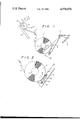
FIG. 1 is a schematic view showing a web feed mechanism according to one embodiment of the present invention; and
FIG. 2 is an enlarged schematic view of the web feed mechanism of FIG. 1.
DESCRIPTION OF THE PREFERRED EMBODIMENT
The present invention is described with reference to a feed mechanism for feeding a web, namely the heat transfer carbon paper or ribbon of a heat transfer type thermal printer. However, the invention is not limited as to the webs to be fed thereby.
As shown in FIG. 1, the heat transfer carbon paper or other material, flexible web 1 is held in the form of a roll on a holding core 2 that is fixed in position on the frame (not shown) of a printer. The heat transfer carbon paper 1 is let off the core 2 and is fed into a clearance between a thermal head 3 and a platen roller 4 so that the carbon paper web can be used to print a continuous separate web of labels L. The web 1 is fed out by the coaction of the platen roller 4 and a follower roller 5.
A lever 6, which acts as a carrier, is hinged by a pin 7 on the frame of the printer. The lever 6 is always biased by the biasing force of a coil spring 8 so that its main arm is biased toward the core 2, i.e., toward the outermost winding of the paper roll 1 (i.e., in the direction of arrow A). The lever 6 can swing toward and away from the core 2 (i.e., in the directions of arrows A and B) for following changes in the external diameter of the paper roll 1.
The lever 6 carries a slide plate 9 on the portion which comes close to the paper roll 1 and at the side facing that roll. The slide plate 9 is carried or supported on the lever 6 by a guide shaft 10 that is anchored to the lever 6 such that it can slide along the longitudinal directions of the lever 6, which are the tangential directions of the paper roll 1. The tangential directions are forward in the direction of arrow C, the direction in which the paper is to be let off from the paper roll, and backward in the direction of arrow D, the direction in which the paper is to be taken up again onto the paper roll 1. The slide plate 9 is also biased backward in the direction D at all times by the biasing force of backspin coil spring 11. At the same time, the slide plate 9 is biased toward the core 2 along the guide shaft 10 and the lever 6 by the biasing force of the coil spring 8. As a result, the slide plate 9 applies drag to the outermost winding of the paper roll 1 being fed.
In order to ensure that drag will occur, a drag rubber 12 covers that surface of the slide plate 9, which is to be brought into contact with the outermost winding of the paper roll 1. The drag rubber 12 has a friction face that contacts that outermost paper winding. The friction face of the drag rubber 12 is shaped to extend generally flat along the tangential directions of the paper roll 1. But, it is bent, at its trailing end, in a direction away from the core 2 for enabling the drag rubber to smoothly contact the outermost winding of the paper roll 1.
The operation of this web feed mechanism is now described.
When the heat transfer carbon paper 1 is pulled from its leading end and is unrolled in accordance with the progress of the printing operation at the thermal head 3, friction force is established between the drag rubber 12 and the carbon paper web 1 so that the slide is shifted forward of the carrier and the biasing force of backspin coil spring is strengthened by the pulling force on web 1 through the friction force established between rubber 12 and the web. The let-off portion of the carbon paper web 1 is dragged and tensed by the slide plate 9 until the slide plate 9 has been moved in the forward direction C into a first position, indicated by solid lines in FIG. 2. This occurs during one feed stroke of the carbon paper web 1 against the biasing force of the coil spring 11 being strengthened.
Once the pulling force on the web 1 overcomes the biasing force of the coil spring 11 during that feed stroke and fully compresses the spring 11, the let-off portion of the carbon paper web 1 is thereafter pulled to frictionally slide on the surface of the drag rubber 12. As a result, the paper roll 1 is revolved to stepwise let off one pitch of the carbon paper web 1 having a length corresponding to a turn of the platen roller 4. At this particular instant, i.e., just at the end of the feed stroke, the slide plate 9 still takes the first position where it is shifted in the direction C with the coil spring 11 compressed.
After the feed stroke, when the pulling force on the web 1 is weakened to zero, the biasing force of the compressed coil spring 11 causes the slide plate 9 to frictionally or smoothly slide in the backward direction D along the outermost winding of the paper roll 1 and into a second or initial position, which is indicated by doubledotted lines in FIG. 2. The frictional engagement between the slide and the roll 1 enables biasing force of spring 11 to thereby return the paper roll 1. The weakening of the pulling force on the let-off portion of the paper roll may also be caused by the slackness of that let-off portion the running path, as indicated by a double-dotted line in FIG. 1. The slackness is due to the overrun of the let-off web portion, because the turn of the platen roller 4 is a stepwise or intermittent one so that it imparts an inertia at some level to the carbon paper web 1. The slackness can be absored through the backward frictional sliding movement of the slide plate 9 and the drag rubber 12 in the direction D, which is caused by the biasing force of the backspin coil spring 11. The friction turns the paper roll 1 in the backward direction, as indicated by letter E in FIG. 2, for eliminating the slackness in the web.
By repeating the stepwise operations thus far described, the slide plate 9 slides in the forward direction C and then in the backward direction D to eliminate the slackness of the let-off carbon paper web 1 on its running path. This prevents generation of noises.
The simple dragging device of the feed mechanism of the prior art produces slip loss of the heat transfer carbon paper web 1, which is caused at the thermal head 3 at the rise in the rotations of the platen roller 4. In the invention, this can be absorbed and dropped by the quick sliding movement of the slide plate 9 in the forward direction C. Moreover, the carbon paper web 1 on the running path can always be held under constant tension by the drag which is ensured as a result of the frictional sliding movements of the slide plate 9 in the directions C and D and by the biasing force of the lever 6 in the direction A.
The present invention has been described as applied to a printer of stepwise feed type, but it can be applied to any feeding mechanism. Moreover, the application of the present invention should not be limited to the heat transfer carbon paper having a very small thickness but to any suitable web.
If the present invention is applied to a printer of the continous feed type, for example, the backspin coil spring 11 may bias the slide plate 9 in the backward direction D during the pulling operation to hold the let-off portion of the carbon paper 1 under tension caused by the balance between the drag and the pulling force.
As has been described herein, according to the present invention, a very thin web, such as heat transfer carbon paper, can be subjected to back tension while assuredly running forward and backward in the feed direction. As a result, no slackness occurs in the web on the running path so that the let-off portion of the web can be prevented from generating noises and/or from loose or undulating runs, which might otherwise be caused by the fluctuations or interruptions of the tension applied to the web.
Although the present invention has been described in connection with a preferred embodiment thereof, many variations and modifications will now become apparent to those skilled in the art. It is preferred, therefore, that the present invention be limited not by the specific disclosure herein, but only by the appended claims.