US4577388A - Method of cutting apertures in lining in underground pipes - Google Patents
Method of cutting apertures in lining in underground pipes Download PDFInfo
- Publication number
- US4577388A US4577388A US06/669,780 US66978084A US4577388A US 4577388 A US4577388 A US 4577388A US 66978084 A US66978084 A US 66978084A US 4577388 A US4577388 A US 4577388A
- Authority
- US
- United States
- Prior art keywords
- lining
- side connection
- cutter
- pipeline
- passageway
- Prior art date
- Legal status (The legal status is an assumption and is not a legal conclusion. Google has not performed a legal analysis and makes no representation as to the accuracy of the status listed.)
- Expired - Lifetime
Links
Images


Classifications
-
- F—MECHANICAL ENGINEERING; LIGHTING; HEATING; WEAPONS; BLASTING
- F16—ENGINEERING ELEMENTS AND UNITS; GENERAL MEASURES FOR PRODUCING AND MAINTAINING EFFECTIVE FUNCTIONING OF MACHINES OR INSTALLATIONS; THERMAL INSULATION IN GENERAL
- F16L—PIPES; JOINTS OR FITTINGS FOR PIPES; SUPPORTS FOR PIPES, CABLES OR PROTECTIVE TUBING; MEANS FOR THERMAL INSULATION IN GENERAL
- F16L55/00—Devices or appurtenances for use in, or in connection with, pipes or pipe systems
- F16L55/26—Pigs or moles, i.e. devices movable in a pipe or conduit with or without self-contained propulsion means
- F16L55/265—Pigs or moles, i.e. devices movable in a pipe or conduit with or without self-contained propulsion means specially adapted for work at or near a junction between a main and a lateral pipe
-
- B—PERFORMING OPERATIONS; TRANSPORTING
- B23—MACHINE TOOLS; METAL-WORKING NOT OTHERWISE PROVIDED FOR
- B23D—PLANING; SLOTTING; SHEARING; BROACHING; SAWING; FILING; SCRAPING; LIKE OPERATIONS FOR WORKING METAL BY REMOVING MATERIAL, NOT OTHERWISE PROVIDED FOR
- B23D21/00—Machines or devices for shearing or cutting tubes
- B23D21/02—Machines or devices for shearing or cutting tubes otherwise than in a plane perpendicular to the axis of the tube, e.g. for making mitred cuts, for making bicycle frames
-
- B—PERFORMING OPERATIONS; TRANSPORTING
- B23—MACHINE TOOLS; METAL-WORKING NOT OTHERWISE PROVIDED FOR
- B23Q—DETAILS, COMPONENTS, OR ACCESSORIES FOR MACHINE TOOLS, e.g. ARRANGEMENTS FOR COPYING OR CONTROLLING; MACHINE TOOLS IN GENERAL CHARACTERISED BY THE CONSTRUCTION OF PARTICULAR DETAILS OR COMPONENTS; COMBINATIONS OR ASSOCIATIONS OF METAL-WORKING MACHINES, NOT DIRECTED TO A PARTICULAR RESULT
- B23Q9/00—Arrangements for supporting or guiding portable metal-working machines or apparatus
- B23Q9/0014—Portable machines provided with or cooperating with guide means supported directly by the workpiece during action
-
- B—PERFORMING OPERATIONS; TRANSPORTING
- B26—HAND CUTTING TOOLS; CUTTING; SEVERING
- B26F—PERFORATING; PUNCHING; CUTTING-OUT; STAMPING-OUT; SEVERING BY MEANS OTHER THAN CUTTING
- B26F1/00—Perforating; Punching; Cutting-out; Stamping-out; Apparatus therefor
- B26F1/38—Cutting-out; Stamping-out
- B26F1/3806—Cutting-out; Stamping-out wherein relative movements of tool head and work during cutting have a component tangential to the work surface
-
- B—PERFORMING OPERATIONS; TRANSPORTING
- B29—WORKING OF PLASTICS; WORKING OF SUBSTANCES IN A PLASTIC STATE IN GENERAL
- B29C—SHAPING OR JOINING OF PLASTICS; SHAPING OF MATERIAL IN A PLASTIC STATE, NOT OTHERWISE PROVIDED FOR; AFTER-TREATMENT OF THE SHAPED PRODUCTS, e.g. REPAIRING
- B29C63/00—Lining or sheathing, i.e. applying preformed layers or sheathings of plastics; Apparatus therefor
- B29C63/0004—Component parts, details or accessories; Auxiliary operations
- B29C63/0013—Removing old coatings
-
- F—MECHANICAL ENGINEERING; LIGHTING; HEATING; WEAPONS; BLASTING
- F16—ENGINEERING ELEMENTS AND UNITS; GENERAL MEASURES FOR PRODUCING AND MAINTAINING EFFECTIVE FUNCTIONING OF MACHINES OR INSTALLATIONS; THERMAL INSULATION IN GENERAL
- F16L—PIPES; JOINTS OR FITTINGS FOR PIPES; SUPPORTS FOR PIPES, CABLES OR PROTECTIVE TUBING; MEANS FOR THERMAL INSULATION IN GENERAL
- F16L55/00—Devices or appurtenances for use in, or in connection with, pipes or pipe systems
- F16L55/16—Devices for covering leaks in pipes or hoses, e.g. hose-menders
- F16L55/179—Devices for covering leaks in pipes or hoses, e.g. hose-menders specially adapted for bends, branch units, branching pipes or the like
-
- Y—GENERAL TAGGING OF NEW TECHNOLOGICAL DEVELOPMENTS; GENERAL TAGGING OF CROSS-SECTIONAL TECHNOLOGIES SPANNING OVER SEVERAL SECTIONS OF THE IPC; TECHNICAL SUBJECTS COVERED BY FORMER USPC CROSS-REFERENCE ART COLLECTIONS [XRACs] AND DIGESTS
- Y10—TECHNICAL SUBJECTS COVERED BY FORMER USPC
- Y10T—TECHNICAL SUBJECTS COVERED BY FORMER US CLASSIFICATION
- Y10T29/00—Metal working
- Y10T29/49—Method of mechanical manufacture
- Y10T29/49995—Shaping one-piece blank by removing material
- Y10T29/49996—Successive distinct removal operations
-
- Y—GENERAL TAGGING OF NEW TECHNOLOGICAL DEVELOPMENTS; GENERAL TAGGING OF CROSS-SECTIONAL TECHNOLOGIES SPANNING OVER SEVERAL SECTIONS OF THE IPC; TECHNICAL SUBJECTS COVERED BY FORMER USPC CROSS-REFERENCE ART COLLECTIONS [XRACs] AND DIGESTS
- Y10—TECHNICAL SUBJECTS COVERED BY FORMER USPC
- Y10T—TECHNICAL SUBJECTS COVERED BY FORMER US CLASSIFICATION
- Y10T409/00—Gear cutting, milling, or planing
- Y10T409/30—Milling
- Y10T409/303752—Process
- Y10T409/303808—Process including infeeding
-
- Y—GENERAL TAGGING OF NEW TECHNOLOGICAL DEVELOPMENTS; GENERAL TAGGING OF CROSS-SECTIONAL TECHNOLOGIES SPANNING OVER SEVERAL SECTIONS OF THE IPC; TECHNICAL SUBJECTS COVERED BY FORMER USPC CROSS-REFERENCE ART COLLECTIONS [XRACs] AND DIGESTS
- Y10—TECHNICAL SUBJECTS COVERED BY FORMER USPC
- Y10T—TECHNICAL SUBJECTS COVERED BY FORMER US CLASSIFICATION
- Y10T409/00—Gear cutting, milling, or planing
- Y10T409/30—Milling
- Y10T409/304424—Means for internal milling
Definitions
- This invention relates to a method of and apparatus for the cutting of apertures in lining in underground pipes, and in particular is concerned with the re-establishment of side connections to a pipe which has been lined by a lining process as described in either of our U.S. Pat. Nos. 4,009,063 and 4,064,211.
- an underground pipeline or passageway is lined by means of a flexible lining comprising a resin absorbent material, which is soaked in curable resin, and the lining whilst still flexible, is shaped to the passage interior, and is allowed to cure to form a hard lining, thereby to complete an effective lining operation.
- the lining material will extend over pipe apertures forming side or branch connections, and these must be re-established in order that the pipeline can function as it did prior to the lining operation.
- the re-establishment of the side connections will entail cutting out or cutting away the protion of the lining which covers each side connection, and as the pipelines which are lined by the process in either of the above U.S. patents are invariably located underground, the matter of re-establishing the side connections is one of substantial difficulty.
- an equipment is used for the re-establishment of said connections, which equipment is designed to cut away the portion of the lining covering each side connection to be re-established, such device comprising a unit which is for movement along the inside of the passageway, such unit having a T.V. camera which is controllable from ground level by a control means whereby the angle of viewing of the camera may be adjusted, enabling the camera to view each side connection location, and the region viewed by the camera is of course displayed at ground level on suitable display means, for example a T.V. monitor.
- the unit also has a cutter which can be manipulated from ground level, and the operator controlling the re-establishment of the side connection process, simply manipulates the cutter by viewing the display means, thereby to re-establish the side connection. Whilst this procedure operates satisfactorily, it does have a number of problems, the first being that the process is extremely slow and depends upon the efficiency of the operator who has to judge (by viewing the T.V. screen) the cutting operation. Because it is quite possible that there will be liquid deposit of resin and/or water behind each portion of the lining covering a side connection, when the first penetrating cut is made in that portion of the lining, there frequently will be a discharge of said deposit into the pipeline or passageway, which can obscure the T.V. camera, making further cutting work extremely difficult. Also, it is difficult for the operator to judge whether or not he has cut away sufficient of the lining material to restore the side connection to the size it was before the lining operation.
- the present invention seeks to provide a method of re-establishing side connections to a pipeline or passageway, especially one which is located underground, whereby the difficulties encountered in the known method will be obviated or mitigated.
- a method of re-establishing side connections to a pipeline or passageway which has been lined with a lining which covers the side connections comprises the utilisation of a cutter which moves in a controlled fashion by the following of a predetermined path corresponding to the shape of cut to be made in the lining.
- the predetermined path may be defined by means of a template or profile which is either followed manually by means of a stylus, or automatically by means of computing central equipment.
- the presetting of the contour may be achieved by pre-programming the computing control equipment, and the pre-programming may be by making an assumption as to the type and size of side connection to be cut, as it is shown in particular that all side connections, or nearly all side connections are of a particular type or types.
- the programming of the computing equipment may be by plotting the shape of the side connection aperture prior to the lining of same by utilising a camera and cutter unit in the passageway, and by positioning the cutter in a particular fashion in relation to the side connection aperture, and recording the various positions of the cutter, thereby to pre-programme the computing apparatus in accordance with the side connection contour.
- the computing apparatus may cause the cutter in the eventual cutting operation to follow the contour automatically, or may cause a profile to be displayed on a cathode ray tube, which profile is traced by an operator using a manual stylus, the movement of the stylus being duplicated by the movement of the cutter during the cutting operation.
- the invention also extends to apparatus capable of performing the method.
- FIG. 1 illustrates in perspective view a section of underground pipeline or passageway to be lined, and having side connections to be re-established after the lining operation;
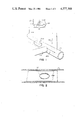
- FIG. 2 shows a length of the lined pipeline in section, prior to cutting out of the lateral connection
- FIG. 3 illustrates a cutter and camera unit usable in accordance with the invention
- FIG. 4 illustrates the length of pipeline shown in FIG. 2, prior to lining
- FIGS. 5, 6 and 7 respectively illustrate three modes in which the cutter can move in re-establishing the side connection.
- FIG. 1 there is shown a pipeline 10 which is located underground, and which is required to be lined with a flexible, resin impregnated lining in the manner as described in U.S. Pat. No. 4,009,063 or 4,064,211 to rehabilitate the pipe, which may be in a state of disrepair, or to change the use of the pipe.
- the pipe may for example be a sewer pipe, and is shown as having side connections 12, 14.
- FIG. 1 also shows that there is located at ground level a control vehicle 16 in which an operator sits.
- the vehicle is provided with a television monitor 20, for the inspection of the pipe as will be explained, and a control line 22 extends from the vehicle 16 to a camera and cutting unit 24 located in the pipe 10. This unit is in use pulled or propelled through the pipe 10, for example as indicated by the arrow 26.
- FIG. 3 illustrates diagrammatically a form of cutter and camera unit 24, which can be used in the process of the invention.
- the unit is provided with a pair of skids 40, 42 which support a chassis 44 having the appropriate drive motors (not shown) and a pull shackle 46 is located at one end of the unit and is mounted on the skids 42, whilst a similar shackle 48 is provided on the unit and mounted at the other end of the skids 40, 42.
- a T.V. camera 50 is mounted on chassis 44 and is for viewing the interior of the pipe 10 before and after the lining is inserted, and this camera can pivot about two orthogonal axes, as shown by arrows 52 and 54, whereby any location of the pipe or lining can be viewed by the camera.
- a cutter 56 which can be driven about the axis 58 to effect the cutting operation. Additionally, the cutter unit 56 can be pivoted about the axis of the pipe 10 or an axis parallel thereto as shown by arrow 59, and to give the cutter universal movement, the cutter can be moved axially of the pipe as indicated by arrow 60.
- the various drives for the cutter and camera are mounted in the chassis 44 and therefore are not shown. These drives are controlled from a control unit in the control vehicle 16 either on selection by the operator 18, or automatically in re-establishing a side connection in accordance with the present invention.
- FIG. 2 shows in cross section a portion of the pipe 10 in the region of the side connection 12, after the pipe 10 has been lined by means of a lining 28 which is of rigid, cured synthetic resin, having embedded therein a resin absorbent material such as a felt, the lining 28 extending across and covering the side connection opening.
- a lining 28 which is of rigid, cured synthetic resin, having embedded therein a resin absorbent material such as a felt, the lining 28 extending across and covering the side connection opening.
- This side connection which must be re-established, and conventionally it is re-established by controlling a cutter when in the pipe 10, from the vehicle 16, by observing the cutting operation on the television 20 and by manipulating the cutter to reinstate the side connection.
- This process can be difficult and time consuming if the camera lens becomes obscured by discharge of fluid into the pipe upon first penetration of the cutter 56 through the lining material 28 covering side connection 12.
- the present invention is concerned with a means for more effectively and positively re-establishing a side connection.
- the camera and cutter unit 24 Prior to the placement of the lining 28, the camera and cutter unit 24 is drawn through the pipe 10 so as to survey the same and ascertain the position of the side connections, such as 12 and 14, along the length of the pipe.
- the cutter is zeroed in on the approximate centre of the side connection as indicated in FIG. 4 by reference A.
- the operator marks out the quadrants of the side connection as shown at points B, C, D and E, the control mechanism storing each position in digital form in its memory.
- the motors which are used to drive the cutter and camera are stepping motors, and the stepping motors respond accurately to the positions A,B,C,D and E in digital form.
- the cutter removes the memorised shape on instructions from the pre-programmed control equipment. Cutting may proceed by the cutter entering at the centre point of the portion of lining to be cut out, and then it can proceed for example, in the fashion shown in FIG. 5, FIG. 6, or FIG. 7. In FIG. 5, the cutter moves radially outwards and then traces the side connection contour step fashion as shown by reference 34. In FIG. 6, the cutter mooes radially outwards and then sweeps horizontally, stepping down after each pass as shown in FIG. 6 by reference 30. In FIG. 7, the cutter moves from the centre spirally as shown by reference 32. The details of the information stored in the memory can be displayed for example on a cathode ray tube so that the progress of the cutter can be observed.
- the cutter can be made to follow a template.
- the template may be in hardware form or it may be a contour displayed on a cathode ray tube.
- the operator may move a stylus along the contour line displayed or the outer edge of the template when in hardware form, whereby the cutter follows the movement faithfully and thereby effects the cutting operation to re-establish side connections.
- FIG. 4 also shows how the side connection will look after cutting, and it will be seen that the aperture has been accurately recreated, enabling the discharge of the liquid from the side connection into the main pipe.
- the present invention provides an effective means for quickly and efficiently re-establishing side connections in a pipeline or passageway which has been lined with a rigid lining tube, for example as in accordance with the method set out in U.S. Pat. No. 4,009,063 or 4,064,211.
Abstract
Description
Claims (2)
Applications Claiming Priority (2)
| Application Number | Priority Date | Filing Date | Title |
|---|---|---|---|
| GB8103660 | 1981-02-06 | ||
| GB8103660A GB2092493B (en) | 1981-02-06 | 1981-02-06 | A method of cutting side connectors in the lining of an underground pipe |
Related Parent Applications (1)
| Application Number | Title | Priority Date | Filing Date |
|---|---|---|---|
| US06346866 Continuation | 1982-02-08 |
Publications (1)
| Publication Number | Publication Date |
|---|---|
| US4577388A true US4577388A (en) | 1986-03-25 |
Family
ID=10519486
Family Applications (1)
| Application Number | Title | Priority Date | Filing Date |
|---|---|---|---|
| US06/669,780 Expired - Lifetime US4577388A (en) | 1981-02-06 | 1984-11-09 | Method of cutting apertures in lining in underground pipes |
Country Status (2)
| Country | Link |
|---|---|
| US (1) | US4577388A (en) |
| GB (1) | GB2092493B (en) |
Cited By (65)
| Publication number | Priority date | Publication date | Assignee | Title |
|---|---|---|---|---|
| US4657450A (en) * | 1985-03-19 | 1987-04-14 | Kraftwerk Union Aktiengesellschaft | Machining tool for pipes |
| US4657449A (en) * | 1986-05-12 | 1987-04-14 | J. Marich & Sons | Internal sewage line stub cutting tool having automatic bit adjustment |
| US4701988A (en) * | 1984-03-24 | 1987-10-27 | Insituform International N.V. | Relating to cutters |
| US4773115A (en) * | 1985-10-08 | 1988-09-27 | Systems Canada Limited | Sewer cleaning device |
| WO1988007919A1 (en) * | 1987-04-14 | 1988-10-20 | Ashimori Kogyo Kabushiki Kaisha | Apparatus for boring at branching portion of lined pipe |
| US4785512A (en) * | 1987-03-31 | 1988-11-22 | Alwin Sigel | Machine for repairing and sealing conduits |
| US4819721A (en) * | 1987-06-09 | 1989-04-11 | Long Technologies, Inc. | Remotely controlled articulatable hydraulic cutter apparatus |
| US4954023A (en) * | 1989-09-27 | 1990-09-04 | Scott Tech International, Inc. | Internal cutting head for drifting pipe |
| US4955951A (en) * | 1988-03-01 | 1990-09-11 | Kabushiki Kaisha Iseki Kaihatsu Koki | Boring apparatus |
| US4986314A (en) * | 1984-12-14 | 1991-01-22 | Kunststoff-Technik Ag Himmler | Apparatus for carrying out repair works on a damaged pipeline which a person cannot get through |
| US5000630A (en) * | 1989-01-17 | 1991-03-19 | The Boeing Company | Bit for forming holes in composite materials |
| WO1991011283A1 (en) * | 1990-01-25 | 1991-08-08 | Trb Specialty Rehabilitation, Inc. | Lateral cutter device |
| US5044824A (en) * | 1990-05-01 | 1991-09-03 | Long Technologies, Inc. | Method and apparatus for locating a service pipe outlet transversely connected to a lined main pipe |
| US5046903A (en) * | 1988-01-27 | 1991-09-10 | Kabushiki Kaisha Iseki Kaihatsu Koki | Method and apparatus for conducting operation in pipe |
| US5054187A (en) * | 1987-09-30 | 1991-10-08 | Sika Robotics Ag | Method and means for remote-controlled sheathing installation when renovating pipelines |
| US5062187A (en) * | 1989-09-27 | 1991-11-05 | Scott Tech International, Inc. | Internal cutting head for drifting pipe |
| US5088553A (en) * | 1990-01-25 | 1992-02-18 | Trb Specialty Rehabilitation, Inc. | Lateral cutter device |
| US5150989A (en) * | 1990-05-01 | 1992-09-29 | Long Technologies, Inc. | Method and apparatus for locating a service pipe outlet transversely connected to a lined main pipe |
| US5153718A (en) * | 1990-11-16 | 1992-10-06 | Jack Massar | Cutting apparatus with viewer |
| US5155941A (en) * | 1989-09-18 | 1992-10-20 | Olympus Optical Co., Ltd. | Industrial endoscope system having a rotary treatment member |
| US5197540A (en) * | 1987-04-14 | 1993-03-30 | Ashimori Kogyo Kabushiki Kaisha | Boring device for lining material in branched portions of lined conduit |
| US5238338A (en) * | 1987-12-21 | 1993-08-24 | Canalcrab S.A. | Machining device operating inside a canalization |
| US5285817A (en) * | 1989-01-12 | 1994-02-15 | Sika Robotics | Remote-controlled insertion of sheathing in inaccessible manifolds and junctions |
| US5368423A (en) * | 1994-02-03 | 1994-11-29 | Inliner U.S.A., Inc. | Robotic cutter |
| US5378092A (en) * | 1991-08-05 | 1995-01-03 | Griner; Ward J. | Apparatus for cutting a hole in a pipe liner |
| US5423352A (en) * | 1989-01-12 | 1995-06-13 | Sika Robotics Ag | Remote-controlled insertion of sheathing in inaccessible manifolds and junctions |
| US5451351A (en) * | 1991-09-13 | 1995-09-19 | Composite Components, Inc. | Method for rehabilitating a pipe with a liner having an electrically conductive layer |
| US5577864A (en) * | 1991-12-23 | 1996-11-26 | Insituform B.V. | Apparatus relating to the linings of pipelines and passageways |
| US5653555A (en) * | 1995-05-19 | 1997-08-05 | Inliner, U.S.A. | Multiple resin system for rehabilitating pipe |
| US5699838A (en) * | 1995-05-22 | 1997-12-23 | Inliner, U.S.A. | Apparatus for vacuum impregnation of a flexible, hollow tube |
| US5925409A (en) * | 1997-08-27 | 1999-07-20 | Reichhold, Inc. | Resins for lining surfaces |
| US5960882A (en) * | 1997-01-23 | 1999-10-05 | Insituform (Netherlands) B.V. | Dual-ended apparatus for cutting openings in lined conduits |
| US5992247A (en) * | 1998-04-23 | 1999-11-30 | Aries Industries Incorporated | Apparatus for inspecting lateral sewer pipes |
| US6012526A (en) * | 1996-08-13 | 2000-01-11 | Baker Hughes Incorporated | Method for sealing the junctions in multilateral wells |
| US6386797B1 (en) | 2001-02-02 | 2002-05-14 | Stephen V. Gearhart | Conduit liner cutter |
| US6505525B2 (en) | 2000-05-12 | 2003-01-14 | Aries Industries Incorporated | Apparatus and method for inspecting lateral sewer pipes |
| US6692802B1 (en) | 1997-08-27 | 2004-02-17 | Reichhold, Inc. | Resins for lining surfaces |
| US20040159435A1 (en) * | 2002-11-07 | 2004-08-19 | Clayton Plucheck | Apparatus and methods to complete wellbore junctions |
| US20040175235A1 (en) * | 2002-11-13 | 2004-09-09 | Redzone Robotics, Inc. | Pipeline rehabilitation systems |
| US20050107001A1 (en) * | 2003-11-18 | 2005-05-19 | Dieter Moeller | Grinding apparatus for blending defects on turbine blades and associated method of use |
| US20050115338A1 (en) * | 2003-11-26 | 2005-06-02 | Mcgrew R. M. | Method and apparatus for performing sewer maintenance with a thermal sensor |
| US20050145079A1 (en) * | 2003-12-29 | 2005-07-07 | Rubino Daniel L. | Drain line re-perforator device |
| US20050161100A1 (en) * | 2002-06-19 | 2005-07-28 | Robert Pleydon | Inversion liner and liner components for conduits |
| US7097539B2 (en) | 2003-11-18 | 2006-08-29 | Dieter Moeller | Rotary grinding apparatus for blending defects on turbine blades and associated method of use |
| US20060200205A1 (en) * | 2005-03-01 | 2006-09-07 | Haller Matthew I | Systems and methods for treating a patient with multiple stimulation therapies |
| US20060290779A1 (en) * | 2005-01-18 | 2006-12-28 | Reverte Carlos F | Autonomous inspector mobile platform |
| US7249918B1 (en) | 2005-02-23 | 2007-07-31 | Bowman Thomas W | Cutting machine |
| US20070284876A1 (en) * | 2006-04-27 | 2007-12-13 | Polivka Richard C | Reinstatement of an existing connection in a lined conduit |
| US20080066604A1 (en) * | 2006-08-11 | 2008-03-20 | Alstom Technology Ltd. | Tube stub removal apparatus |
| US20080068601A1 (en) * | 2006-09-15 | 2008-03-20 | Thayer Scott M | Manhole modeler |
| US7364392B1 (en) | 2006-02-23 | 2008-04-29 | Bowman Thomas W | Motor module for a reinstatement cutting machine |
| US20080135226A1 (en) * | 2006-12-08 | 2008-06-12 | Lewis Evan G | Wireline supported tubular mill |
| US20090223335A1 (en) * | 2008-03-10 | 2009-09-10 | Shonan Gosei-Jushi Seishakusho K.K. | In-pipe work robot |
| US20090223336A1 (en) * | 2008-03-07 | 2009-09-10 | Shonan Gosei-Jushi Seisakusho K.K. | Apparatus for cutting lateral wall of pipe |
| US7720570B2 (en) | 2004-10-01 | 2010-05-18 | Redzone Robotics, Inc. | Network architecture for remote robot with interchangeable tools |
| US20100218624A1 (en) * | 2008-11-03 | 2010-09-02 | Atwood Christopher C | Device for pipe inspection and method of using same |
| US20110232793A1 (en) * | 2010-03-24 | 2011-09-29 | Ina Acquisition Corp. | Wedge type plug and method of plugging a lateral line |
| US8170715B1 (en) * | 2005-01-25 | 2012-05-01 | Redzone Robotics, Inc. | Methods and devices for automated work in pipes based on impedance control |
| US20140169886A1 (en) * | 2012-11-07 | 2014-06-19 | Neil ROGERS | Lateral reinstatement cutter and single access point method of use |
| US20150258615A1 (en) * | 2012-10-31 | 2015-09-17 | Fuji Machine Mfg. Co., Ltd. | Workpiece machining apparatus |
| US20160047400A1 (en) * | 2014-08-15 | 2016-02-18 | Jeffrey M. Tanner | Pipe Tool Positioning System |
| US20190107715A1 (en) * | 2016-03-24 | 2019-04-11 | Pipetronics Gmbh & Co. Kg | Method for uncovering a branch in a pipe system by virtual projection thereof |
| US10316602B2 (en) * | 2013-06-14 | 2019-06-11 | Welltec A/S | Downhole machining system and method |
| US10955081B1 (en) * | 2019-11-11 | 2021-03-23 | Jonathan R Griffith | Lateral reinstatement cutter |
| US11254045B2 (en) | 2019-08-26 | 2022-02-22 | Jeffrey M. Tanner | Method and system for lining pipes |
Families Citing this family (23)
| Publication number | Priority date | Publication date | Assignee | Title |
|---|---|---|---|---|
| DE3627620A1 (en) * | 1986-08-14 | 1988-02-25 | Weiss Karl Hoch Tief | METHOD FOR PUTTING PIPES INTO A PIPELINE |
| EP0282588B1 (en) * | 1986-08-19 | 1991-07-03 | Tokyo Gas Kabushiki Kaisha | Device for boring lining of pipe line |
| CH673884A5 (en) * | 1987-06-15 | 1990-04-12 | Ametex Ag | |
| WO1992006323A1 (en) * | 1990-09-28 | 1992-04-16 | W.E. Rawson Limited | Improvements in or relating to conduit lining layers |
| GB9225528D0 (en) | 1992-12-07 | 1993-01-27 | Insituform Group Ltd | Improvements relating to the lining of pipelines and passageways |
| USD584423S1 (en) | 2006-12-14 | 2009-01-06 | Anchor Wall Systems, Inc. | Molded surface of a concrete product |
| USD588713S1 (en) | 2007-01-19 | 2009-03-17 | Anchor Wall Systems, Inc. | Molded surface of a concrete product |
| USD598135S1 (en) | 2007-03-14 | 2009-08-11 | Anchor Wall Systems, Inc. | Molded surface of a concrete product |
| USD585567S1 (en) | 2007-05-14 | 2009-01-27 | Anchor Wall Systems, Inc. | Molded surface of a concrete product |
| USD588714S1 (en) | 2007-08-06 | 2009-03-17 | Anchor Wall Systems, Inc. | Molded surface of a concrete product |
| USD620614S1 (en) | 2008-03-13 | 2010-07-27 | Anchor Wall Systems, Inc. | Molded surface of a concrete product |
| USD620134S1 (en) | 2009-05-19 | 2010-07-20 | Anchor Wall Systems, Inc. | Molded surface of a concrete product |
| GB2475482B (en) * | 2009-11-18 | 2014-09-10 | Waterflow Group Plc | Method and apparatus for creating apertures in a pipeline |
| USD636093S1 (en) | 2010-03-02 | 2011-04-12 | Anchor Wall Systems, Inc. | Molded surface of a concrete product |
| USD653772S1 (en) | 2010-11-29 | 2012-02-07 | Anchor Wall Systems, Inc. | Molded surface of a concrete product |
| USD645165S1 (en) | 2010-12-03 | 2011-09-13 | Anchor Wall Systems, Inc. | Molded surface of a concrete product |
| USD679833S1 (en) | 2011-05-05 | 2013-04-09 | Anchor Wall Systems, Inc. | Molded surface of a concrete product |
| USD678552S1 (en) | 2011-05-05 | 2013-03-19 | Anchor Wall Systems, Inc. | Molded surface of a concrete product |
| USD685923S1 (en) | 2011-05-05 | 2013-07-09 | Anchor Wall Systems, Inc. | Molded surface of a concrete product |
| USD703346S1 (en) | 2012-09-12 | 2014-04-22 | Anchor Wall Systems, Inc. | Molded surface of a concrete product |
| USD693481S1 (en) | 2012-11-05 | 2013-11-12 | Anchor Wall Systems, Inc. | Molded surface of a concrete product |
| GB2531709A (en) * | 2014-10-20 | 2016-05-04 | Nat Grid Gas Plc | Apparatus and method |
| DE102016105641A1 (en) * | 2016-03-24 | 2017-09-28 | Pipetronics Gmbh & Co. Kg | Method for automatically exposing a branch in a pipeline system |
Citations (2)
| Publication number | Priority date | Publication date | Assignee | Title |
|---|---|---|---|---|
| US4197908A (en) * | 1978-04-06 | 1980-04-15 | Underground Surveys Corporation | Apparatus for porting a side wall of a conduit from interiorly thereof |
| US4442891A (en) * | 1982-03-01 | 1984-04-17 | Insituform International N.V. | Cutters |
-
1981
- 1981-02-06 GB GB8103660A patent/GB2092493B/en not_active Expired
-
1984
- 1984-11-09 US US06/669,780 patent/US4577388A/en not_active Expired - Lifetime
Patent Citations (2)
| Publication number | Priority date | Publication date | Assignee | Title |
|---|---|---|---|---|
| US4197908A (en) * | 1978-04-06 | 1980-04-15 | Underground Surveys Corporation | Apparatus for porting a side wall of a conduit from interiorly thereof |
| US4442891A (en) * | 1982-03-01 | 1984-04-17 | Insituform International N.V. | Cutters |
Cited By (92)
| Publication number | Priority date | Publication date | Assignee | Title |
|---|---|---|---|---|
| US4701988A (en) * | 1984-03-24 | 1987-10-27 | Insituform International N.V. | Relating to cutters |
| US4986314A (en) * | 1984-12-14 | 1991-01-22 | Kunststoff-Technik Ag Himmler | Apparatus for carrying out repair works on a damaged pipeline which a person cannot get through |
| US4657450A (en) * | 1985-03-19 | 1987-04-14 | Kraftwerk Union Aktiengesellschaft | Machining tool for pipes |
| US4773115A (en) * | 1985-10-08 | 1988-09-27 | Systems Canada Limited | Sewer cleaning device |
| US4657449A (en) * | 1986-05-12 | 1987-04-14 | J. Marich & Sons | Internal sewage line stub cutting tool having automatic bit adjustment |
| US4785512A (en) * | 1987-03-31 | 1988-11-22 | Alwin Sigel | Machine for repairing and sealing conduits |
| WO1988007919A1 (en) * | 1987-04-14 | 1988-10-20 | Ashimori Kogyo Kabushiki Kaisha | Apparatus for boring at branching portion of lined pipe |
| US5197540A (en) * | 1987-04-14 | 1993-03-30 | Ashimori Kogyo Kabushiki Kaisha | Boring device for lining material in branched portions of lined conduit |
| US4819721A (en) * | 1987-06-09 | 1989-04-11 | Long Technologies, Inc. | Remotely controlled articulatable hydraulic cutter apparatus |
| US5054187A (en) * | 1987-09-30 | 1991-10-08 | Sika Robotics Ag | Method and means for remote-controlled sheathing installation when renovating pipelines |
| US5238338A (en) * | 1987-12-21 | 1993-08-24 | Canalcrab S.A. | Machining device operating inside a canalization |
| US5046903A (en) * | 1988-01-27 | 1991-09-10 | Kabushiki Kaisha Iseki Kaihatsu Koki | Method and apparatus for conducting operation in pipe |
| US4955951A (en) * | 1988-03-01 | 1990-09-11 | Kabushiki Kaisha Iseki Kaihatsu Koki | Boring apparatus |
| US5285817A (en) * | 1989-01-12 | 1994-02-15 | Sika Robotics | Remote-controlled insertion of sheathing in inaccessible manifolds and junctions |
| US5423352A (en) * | 1989-01-12 | 1995-06-13 | Sika Robotics Ag | Remote-controlled insertion of sheathing in inaccessible manifolds and junctions |
| US5000630A (en) * | 1989-01-17 | 1991-03-19 | The Boeing Company | Bit for forming holes in composite materials |
| US5155941A (en) * | 1989-09-18 | 1992-10-20 | Olympus Optical Co., Ltd. | Industrial endoscope system having a rotary treatment member |
| US4954023A (en) * | 1989-09-27 | 1990-09-04 | Scott Tech International, Inc. | Internal cutting head for drifting pipe |
| US5062187A (en) * | 1989-09-27 | 1991-11-05 | Scott Tech International, Inc. | Internal cutting head for drifting pipe |
| US5088553A (en) * | 1990-01-25 | 1992-02-18 | Trb Specialty Rehabilitation, Inc. | Lateral cutter device |
| WO1991011283A1 (en) * | 1990-01-25 | 1991-08-08 | Trb Specialty Rehabilitation, Inc. | Lateral cutter device |
| US5105882A (en) * | 1990-01-25 | 1992-04-21 | Trb Specialty Rehabilitation, Inc. | Lateral cutter device |
| US5150989A (en) * | 1990-05-01 | 1992-09-29 | Long Technologies, Inc. | Method and apparatus for locating a service pipe outlet transversely connected to a lined main pipe |
| US5044824A (en) * | 1990-05-01 | 1991-09-03 | Long Technologies, Inc. | Method and apparatus for locating a service pipe outlet transversely connected to a lined main pipe |
| US5153718A (en) * | 1990-11-16 | 1992-10-06 | Jack Massar | Cutting apparatus with viewer |
| US5378092A (en) * | 1991-08-05 | 1995-01-03 | Griner; Ward J. | Apparatus for cutting a hole in a pipe liner |
| US5451351A (en) * | 1991-09-13 | 1995-09-19 | Composite Components, Inc. | Method for rehabilitating a pipe with a liner having an electrically conductive layer |
| US5577864A (en) * | 1991-12-23 | 1996-11-26 | Insituform B.V. | Apparatus relating to the linings of pipelines and passageways |
| US5368423A (en) * | 1994-02-03 | 1994-11-29 | Inliner U.S.A., Inc. | Robotic cutter |
| US5653555A (en) * | 1995-05-19 | 1997-08-05 | Inliner, U.S.A. | Multiple resin system for rehabilitating pipe |
| US5699838A (en) * | 1995-05-22 | 1997-12-23 | Inliner, U.S.A. | Apparatus for vacuum impregnation of a flexible, hollow tube |
| US6012526A (en) * | 1996-08-13 | 2000-01-11 | Baker Hughes Incorporated | Method for sealing the junctions in multilateral wells |
| US5960882A (en) * | 1997-01-23 | 1999-10-05 | Insituform (Netherlands) B.V. | Dual-ended apparatus for cutting openings in lined conduits |
| US6692802B1 (en) | 1997-08-27 | 2004-02-17 | Reichhold, Inc. | Resins for lining surfaces |
| US5925409A (en) * | 1997-08-27 | 1999-07-20 | Reichhold, Inc. | Resins for lining surfaces |
| US20040053062A1 (en) * | 1997-08-27 | 2004-03-18 | Hildeberto Nava | Resins for lining surfaces |
| US5992247A (en) * | 1998-04-23 | 1999-11-30 | Aries Industries Incorporated | Apparatus for inspecting lateral sewer pipes |
| USRE38999E1 (en) | 1998-04-23 | 2006-03-07 | Aries Industries, Inc. | Apparatus for inspecting lateral sewer pipes |
| US6505525B2 (en) | 2000-05-12 | 2003-01-14 | Aries Industries Incorporated | Apparatus and method for inspecting lateral sewer pipes |
| US6386797B1 (en) | 2001-02-02 | 2002-05-14 | Stephen V. Gearhart | Conduit liner cutter |
| US20050161100A1 (en) * | 2002-06-19 | 2005-07-28 | Robert Pleydon | Inversion liner and liner components for conduits |
| US7213654B2 (en) | 2002-11-07 | 2007-05-08 | Weatherford/Lamb, Inc. | Apparatus and methods to complete wellbore junctions |
| US20040159435A1 (en) * | 2002-11-07 | 2004-08-19 | Clayton Plucheck | Apparatus and methods to complete wellbore junctions |
| US20040175235A1 (en) * | 2002-11-13 | 2004-09-09 | Redzone Robotics, Inc. | Pipeline rehabilitation systems |
| US7131791B2 (en) | 2002-11-13 | 2006-11-07 | Redzone Robotics, Inc. | Pipeline rehabilitation systems |
| US7112118B1 (en) | 2003-11-18 | 2006-09-26 | Dieter Moeller | Mechanical grinding apparatus for blending defects on turbine blades and associated method of use |
| US6899593B1 (en) * | 2003-11-18 | 2005-05-31 | Dieter Moeller | Grinding apparatus for blending defects on turbine blades and associated method of use |
| US20050107001A1 (en) * | 2003-11-18 | 2005-05-19 | Dieter Moeller | Grinding apparatus for blending defects on turbine blades and associated method of use |
| US20060228993A1 (en) * | 2003-11-18 | 2006-10-12 | Dieter Moeller | Mechanical grinding apparatus for blending defects on turbine blades and associated method of use |
| US7097539B2 (en) | 2003-11-18 | 2006-08-29 | Dieter Moeller | Rotary grinding apparatus for blending defects on turbine blades and associated method of use |
| US7073979B2 (en) | 2003-11-26 | 2006-07-11 | Aries Industries Incorporated | Method and apparatus for performing sewer maintenance with a thermal sensor |
| US20050115338A1 (en) * | 2003-11-26 | 2005-06-02 | Mcgrew R. M. | Method and apparatus for performing sewer maintenance with a thermal sensor |
| US6990879B2 (en) * | 2003-12-29 | 2006-01-31 | Rubino Daniel L | Drain line re-perforator device |
| US20050145079A1 (en) * | 2003-12-29 | 2005-07-07 | Rubino Daniel L. | Drain line re-perforator device |
| US8060257B2 (en) | 2004-10-01 | 2011-11-15 | Redzone Robotics, Inc. | Network architecture for remote robot with interchangeable tools |
| US20100191376A1 (en) * | 2004-10-01 | 2010-07-29 | Redzone Robotics, Inc. | Network architecture for remote robot with interchangeable tools |
| US7720570B2 (en) | 2004-10-01 | 2010-05-18 | Redzone Robotics, Inc. | Network architecture for remote robot with interchangeable tools |
| US20060290779A1 (en) * | 2005-01-18 | 2006-12-28 | Reverte Carlos F | Autonomous inspector mobile platform |
| US8024066B2 (en) | 2005-01-18 | 2011-09-20 | Redzone Robotics, Inc. | Autonomous inspector mobile platform |
| US8170715B1 (en) * | 2005-01-25 | 2012-05-01 | Redzone Robotics, Inc. | Methods and devices for automated work in pipes based on impedance control |
| US7249918B1 (en) | 2005-02-23 | 2007-07-31 | Bowman Thomas W | Cutting machine |
| US7473057B1 (en) | 2005-02-23 | 2009-01-06 | Bowman Thomas W | Cutting machine |
| US20060200205A1 (en) * | 2005-03-01 | 2006-09-07 | Haller Matthew I | Systems and methods for treating a patient with multiple stimulation therapies |
| US7364392B1 (en) | 2006-02-23 | 2008-04-29 | Bowman Thomas W | Motor module for a reinstatement cutting machine |
| US20070284876A1 (en) * | 2006-04-27 | 2007-12-13 | Polivka Richard C | Reinstatement of an existing connection in a lined conduit |
| US8015695B2 (en) * | 2006-04-27 | 2011-09-13 | Ina Acquisition Corp. | Reinstatement of an existing connection in a lined conduit |
| US20080066604A1 (en) * | 2006-08-11 | 2008-03-20 | Alstom Technology Ltd. | Tube stub removal apparatus |
| US8104387B2 (en) * | 2006-08-11 | 2012-01-31 | Alstom Technology Ltd | Tube stub removal apparatus |
| US8467049B2 (en) | 2006-09-15 | 2013-06-18 | RedzoneRobotics, Inc. | Manhole modeler using a plurality of scanners to monitor the conduit walls and exterior |
| US20080068601A1 (en) * | 2006-09-15 | 2008-03-20 | Thayer Scott M | Manhole modeler |
| US20080135226A1 (en) * | 2006-12-08 | 2008-06-12 | Lewis Evan G | Wireline supported tubular mill |
| US7562700B2 (en) * | 2006-12-08 | 2009-07-21 | Baker Hughes Incorporated | Wireline supported tubular mill |
| US20090223336A1 (en) * | 2008-03-07 | 2009-09-10 | Shonan Gosei-Jushi Seisakusho K.K. | Apparatus for cutting lateral wall of pipe |
| US8202142B2 (en) * | 2008-03-07 | 2012-06-19 | Shonan Gosei-Jushi Seisakusho K.K. | Apparatus for cutting lateral wall of pipe |
| US20090223335A1 (en) * | 2008-03-10 | 2009-09-10 | Shonan Gosei-Jushi Seishakusho K.K. | In-pipe work robot |
| US20100218624A1 (en) * | 2008-11-03 | 2010-09-02 | Atwood Christopher C | Device for pipe inspection and method of using same |
| US8525124B2 (en) | 2008-11-03 | 2013-09-03 | Redzone Robotics, Inc. | Device for pipe inspection and method of using same |
| US8820363B2 (en) | 2010-03-24 | 2014-09-02 | Ina Acquisition Corp. | Wedge type plug and method of plugging a lateral line |
| US20110232793A1 (en) * | 2010-03-24 | 2011-09-29 | Ina Acquisition Corp. | Wedge type plug and method of plugging a lateral line |
| US20150258615A1 (en) * | 2012-10-31 | 2015-09-17 | Fuji Machine Mfg. Co., Ltd. | Workpiece machining apparatus |
| US9522429B2 (en) * | 2012-10-31 | 2016-12-20 | Fuji Machine Mfg. Co., Ltd. | Workpiece machining apparatus |
| US20140169886A1 (en) * | 2012-11-07 | 2014-06-19 | Neil ROGERS | Lateral reinstatement cutter and single access point method of use |
| US9512952B2 (en) * | 2012-11-07 | 2016-12-06 | Geoffrey E. Parmer | Lateral reinstatement cutter and single access point method of use |
| US10316602B2 (en) * | 2013-06-14 | 2019-06-11 | Welltec A/S | Downhole machining system and method |
| US20160047400A1 (en) * | 2014-08-15 | 2016-02-18 | Jeffrey M. Tanner | Pipe Tool Positioning System |
| US20170102107A1 (en) * | 2014-08-15 | 2017-04-13 | Jeffrey M. Tanner | Pipe Tool Positioning System |
| US10174877B2 (en) * | 2014-08-15 | 2019-01-08 | Jeffrey M. Tanner | Pipe tool positioning system |
| US9541230B2 (en) * | 2014-08-15 | 2017-01-10 | Jeffrey M. Tanner | Pipe tool positioning system |
| US20190107715A1 (en) * | 2016-03-24 | 2019-04-11 | Pipetronics Gmbh & Co. Kg | Method for uncovering a branch in a pipe system by virtual projection thereof |
| US10761324B2 (en) * | 2016-03-24 | 2020-09-01 | Pipetronics Gmbh & Co. Kg | Method for uncovering a branch in a pipe system by virtual projection thereof |
| US11254045B2 (en) | 2019-08-26 | 2022-02-22 | Jeffrey M. Tanner | Method and system for lining pipes |
| US10955081B1 (en) * | 2019-11-11 | 2021-03-23 | Jonathan R Griffith | Lateral reinstatement cutter |
Also Published As
| Publication number | Publication date |
|---|---|
| GB2092493B (en) | 1983-11-16 |
| GB2092493A (en) | 1982-08-18 |
Similar Documents
| Publication | Publication Date | Title |
|---|---|---|
| US4577388A (en) | Method of cutting apertures in lining in underground pipes | |
| US4822211A (en) | Method and apparatus for laying cable in a pipe | |
| US10591102B2 (en) | Method and apparatus for repairing main and lateral pipes | |
| US5674030A (en) | Device and method for repairing building branch lines in inacessible sewer mains | |
| EP0518978A1 (en) | Apparatus for inspecting the interior of a lateral pipeline | |
| IE922938A1 (en) | Improvements relating to the lining of pipelines and¹passageways | |
| GB2091611A (en) | Cutting of side connections in pipes | |
| US5318395A (en) | Method and apparatus for porting lateral connections in lined pipelines | |
| DE102010044465A1 (en) | Device for rehabilitating a pipe | |
| GB2098300A (en) | Improvements in and relating to the lining of sewers pipes or the like | |
| EP0053346A3 (en) | Method and apparatus for butt welding of plastic pipes of large diameter | |
| DE3627620C2 (en) | ||
| DE8400322U1 (en) | DEVICE FOR OBSERVING AND / OR PROCESSING THE INTERNAL WALL OF TUBULAR CAVES | |
| US20200063906A1 (en) | Drilling device and drilling method | |
| EP0621434A1 (en) | Device for renovating a non-accessible pipeline | |
| DE59006218D1 (en) | Method and device for laying and positioning a pipe in an existing pipe. | |
| EP0554416B1 (en) | Process and device for relining service drains joined to inaccessible main sewage drains | |
| EP3433070A1 (en) | Method for uncovering a branch in a pipe system by virtual projection thereof | |
| JPS61179724A (en) | Hole opening device for detection of ramification hole of lined tube | |
| EP3433528B1 (en) | Method for automatically exposing a branch-off point in a line system | |
| WO1991017325A1 (en) | Method and equipment for use in renovation of sewer pipes | |
| JP2000282561A (en) | Method and device for lining lateral pipe | |
| JPH02232131A (en) | Pipe inside lining material cutting device | |
| JP2688134B2 (en) | Pipe joining device | |
| JP3450036B2 (en) | Method, apparatus and apparatus for cutting the end of a pipe liner |
Legal Events
| Date | Code | Title | Description |
|---|---|---|---|
| STCF | Information on status: patent grant |
Free format text: PATENTED CASE |
|
| AS | Assignment |
Owner name: INSITUFORM INTERNATIONAL, N.V., P.O. BOX 840, CURA Free format text: ASSIGNMENT OF ASSIGNORS INTEREST.;ASSIGNOR:INSITUFORM INTERNATIONAL, INC.,;REEL/FRAME:004659/0122 Effective date: 19861211 Owner name: INSITUFORM INTERNATIONAL, N.V., A CORP OF THE NETH Free format text: ASSIGNMENT OF ASSIGNORS INTEREST;ASSIGNOR:INSITUFORM INTERNATIONAL, INC.,;REEL/FRAME:004659/0122 Effective date: 19861211 |
|
| FEPP | Fee payment procedure |
Free format text: PAYOR NUMBER ASSIGNED (ORIGINAL EVENT CODE: ASPN); ENTITY STATUS OF PATENT OWNER: LARGE ENTITY |
|
| AS | Assignment |
Owner name: INSITUFORM LICENCEES B.V., NETHERLANDS Free format text: ASSIGNMENT OF ASSIGNORS INTEREST.;ASSIGNOR:INSITUFORM INTERNATIONAL N.V.;REEL/FRAME:005041/0235 Effective date: 19880729 |
|
| FPAY | Fee payment |
Year of fee payment: 4 |
|
| AS | Assignment |
Owner name: INSITUFORM (NETHERLANDS) B.V., NETHERLANDS Free format text: ASSIGNMENT OF ASSIGNORS INTEREST.;ASSIGNOR:INSITUFORM LICENSEES B.V.;REEL/FRAME:006344/0851 Effective date: 19921203 |
|
| FPAY | Fee payment |
Year of fee payment: 8 |
|
| FEPP | Fee payment procedure |
Free format text: PAYER NUMBER DE-ASSIGNED (ORIGINAL EVENT CODE: RMPN); ENTITY STATUS OF PATENT OWNER: LARGE ENTITY Free format text: PAYOR NUMBER ASSIGNED (ORIGINAL EVENT CODE: ASPN); ENTITY STATUS OF PATENT OWNER: LARGE ENTITY |
|
| FPAY | Fee payment |
Year of fee payment: 12 |