US4586510A - Apparatus for exercising a paralyzed limb - Google Patents
Apparatus for exercising a paralyzed limb Download PDFInfo
- Publication number
- US4586510A US4586510A US06/635,314 US63531484A US4586510A US 4586510 A US4586510 A US 4586510A US 63531484 A US63531484 A US 63531484A US 4586510 A US4586510 A US 4586510A
- Authority
- US
- United States
- Prior art keywords
- signal
- stimulation
- generating
- limb
- rest
- Prior art date
- Legal status (The legal status is an assumption and is not a legal conclusion. Google has not performed a legal analysis and makes no representation as to the accuracy of the status listed.)
- Expired - Fee Related
Links
Images


Classifications
-
- A—HUMAN NECESSITIES
- A61—MEDICAL OR VETERINARY SCIENCE; HYGIENE
- A61N—ELECTROTHERAPY; MAGNETOTHERAPY; RADIATION THERAPY; ULTRASOUND THERAPY
- A61N1/00—Electrotherapy; Circuits therefor
- A61N1/18—Applying electric currents by contact electrodes
- A61N1/32—Applying electric currents by contact electrodes alternating or intermittent currents
- A61N1/36—Applying electric currents by contact electrodes alternating or intermittent currents for stimulation
- A61N1/36003—Applying electric currents by contact electrodes alternating or intermittent currents for stimulation of motor muscles, e.g. for walking assistance
-
- Y—GENERAL TAGGING OF NEW TECHNOLOGICAL DEVELOPMENTS; GENERAL TAGGING OF CROSS-SECTIONAL TECHNOLOGIES SPANNING OVER SEVERAL SECTIONS OF THE IPC; TECHNICAL SUBJECTS COVERED BY FORMER USPC CROSS-REFERENCE ART COLLECTIONS [XRACs] AND DIGESTS
- Y10—TECHNICAL SUBJECTS COVERED BY FORMER USPC
- Y10S—TECHNICAL SUBJECTS COVERED BY FORMER USPC CROSS-REFERENCE ART COLLECTIONS [XRACs] AND DIGESTS
- Y10S482/00—Exercise devices
- Y10S482/901—Exercise devices having computer circuitry
Abstract
A system for exercising paralyzed human limbs by functional electrical stimulation. The system utilizes simple analog devices including a reference signal generator, a position sensor and an error signal generator. The error signal is integrated to produce a stimulation driving signal for application to stimulation electrodes mounted on the limb. In the disclosed embodiment the paralyzed person may be seated in an exercise chair. The chair is equipped with a pair of loading assemblies which may be attached to the legs of the person so as to yieldingly resist stimulated movement thereof.
Description
This invention relates to apparatus for directing coordinated movement of paralyzed muscles and exercising them to reverse the atrophy resulting from the inactivity which follows the onset of a paralyzing occurrence. A typical prior art device is shown, for instance, in Petrofsky et al Ser. No. 417,935, filed Sept. 14, 1982. Through the use of such devices it has been found possible to exercise paralyzed muscles in a controlled fashion, even after years of inactivity. Such systems operate by applying electrical stimulation to muscles which have been cut off from communication with the brain, as a result of spinal cord damage, stroke, or other neuromuscular conditions involving upper motoneuron dysfunction.
A system as taught by Petrofsky et al includes a microprocessor for generating digital commands indicating a desired motion by a paralyzed limb, a digital-to-analog converter, a plurality of stimulation electrodes, a sensor for sensing motion of the stimulated limb, and an analog-to-digital converter which receives the output of the position sensor and converts it to digital form for use by the microprocessor. The system also includes dynamic load means which apply a resisting force to the paralyzed limb during stimulated motion thereof.
While a system as taught by Petrofsky et al is able to perform numerous complex mathematical manipulations as appropriate for carrying out a variety of sophisticated exercise routines, there exists a need for a simpler device which need not be programmed and which is able to conduct a specified exercise routine for a paralyzed limb, such as a human leg.
This invention provides an effective system based upon simple anlog devices for exercising a paralyzed limb by functional electrical stimulation. The system includes means for generating a reference signal indicating a range of desired limb positions varying from a rest position to a working position and then back to the rest position, and a position sensor for sensing the position of the limb and generating a corresponding position signal. A differential amplifier compares the reference signal with the position signal and generates an error signal representing the observed difference. The error signal is integrated by a stimulus integrator to produce a stimulation driving signal for application to stimulation electrodes mounted on the limb. This stimulates muscular activity in the limb and causes controlled movement thereof from the rest position to the working position and back to the rest position. A loading device, which may comprise a simple weight, resists the movement of the limb to produce muscular exertion.
In preferred embodiment the reference signal is generated by means including a timer which generates a timing signal progressing from a level quiescent value to a timing pulse of predetermined duration and back to the quiescent value. The timing signal is integrated by a reference integrator to produce the reference signal. Such integration of the timing signal produces a reference signal which ramps from a rest value to a working value and then reversly to the rest value. Also in preferred embodiment, the stimulation driving signal is chopped into a pulsatile output signal for application to the stimulation electrodes.
A system constructed in accordance with this invention is relatively inexpensive to produce, easy to operate and fully effective. Desired exercise performance parameters during a contraction cycle may be set by simply turning adjustment potentiometers which control stimulation threshold level, rate of limb extension, target angle of limb extension, time to hold the target angle, and rate of limb return to resting position. Once these parameters are set it is only necessary to trigger the stimulator to cause it to go through its complete contraction cycle sequence. A momentary switch is provided for initiating subsequent contraction cycles. Alternatively, there may be provided a pair of such stimulation units connected to an automatic switching unit through a pair of isolation amplifiers. This permits automatic alternate triggering of contraction cycles for exercising a pair of paralyzed limbs.
Accordingly, it is an object of the present invention to exercise a paralyzed limb through use of a simplified functional electrical stimulation system.
Other objects and advantages of the present invention will be apparent from the following description, the accompanying drawings and the appended claims.
FIG. 1 is a pictorial sketch illustrating a complete system constructed in accordance with this invention;
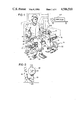
FIG. 2 illustrates apparatus for establishing a resting position for a leg loading assembly;
FIGS. 3A and 3B are an electrical schematic diagram of a pair of stimulator units built in accordance with this invention and connected to a remote control unit; and
FIG. 4 is a schematic diagram illustrating signal waveforms as they appear without position sensor feedback at selected points in the circuitry of FIG. 3B.
FIG. 5 illustrates the chopping signal applied to solid state switch 95.
Apparatus in accordance with the present invention may be utilized as generally illustrated in FIG. 1 and may be configured electrically as illustrated in FIGS. 3A and 3B. TABLE I identifies the components depicted in the figures.
As illustrated in FIG. 1 a paralyzed person who desires electrically induced stimulation of his quadriceps muscles may sit in a chair 10 including a chair back 11, a seat 12, left and right arm rests 13 and 14 and legs 15 through 18. A pair of limb loading assemblies 19 and 20 may be pivotally supported by chair legs 16 and 18, respectively, for stimulated exercising of the patient's left and right legs. Each limb loading assembly includes a support arm 21 pivotally supported at its upper end by an extension of its associated chair leg. Support arm 21 carries a spindle 23 upon which are mounted a cylindrical cushion member 24 and an annular weight 22. The weight 22 is selected to provide the desired amount of resistance against leg movement. Cushion 24 prevents bruising of the patient's legs. Support arm 21 may be provided with a plurality of receiving openings for adjusting the height of spindle 23.
A rotation sensor 76 which may include a potentiometer of conventional design senses the rotation of support arm 21 and provides an electrical indication thereof to a stimulation console 27. As best illustrated in FIG. 2 a spacer member 25 mounted on the chair leg 18 (or 16) provides a predetermined rest position for the support arm.
Electrical stimulation of the quadriceps muscles is provided by four transcutaneous electrodes 28 mounted on the upper legs of the patient as illustrated in FIG. 1. Electrical stimulation signals of appropriate waveform are supplied to electrodes 28 by stimulation console 27 as hereinafter described in detail. The legs may be exercised alternately by alternate depression of switches 142, 143 mounted on chair arms 13 and 14. Depression of one of the switches 142, 143 causes stimulation console 27 to generate stimulation signals which produce gradual contraction and relaxation of the quadriceps muscles in an associated leg of the patient. The entire contraction and relaxation cycle may continue for a period of approximately ten seconds. During this period the leg raises and lowers the associated loading assembly 19 or 20.
Power supplies 50 and 51 are each powered by 115 volt, 60 cycle A.C. current supplied to transformers 101A and 101B. Transformers 101A and 101B convert the 115 volt supply current into a 6.3 volt drive and then step this 6.3 drive back up to 115 volts so as to isolate the high voltage stimulation drive from the outside supply current. An arrangement of diodes, resistors and capacitors, as illustrated, convert the isolated 115 volt supply into a 275 volt D.C. driving potential for application to switch 107. When switch 107 is closed the D.C. drive is supplied via line 205 to one of the transcutaneous electrodes 28. A stimulation driving circuit is then completed through the leg of the patient when the stimulator unit is triggered to produce conduction in a VMOS output transistor 92.
Power supplies 50 and 51 also include a third transformer 110 which produces a 24 volt A.C. signal for application across a rectifier bridge 111. The output from rectifier bridge 111 is utilized as illustrated in FIG. 3A to create +9 volt and -9 volt direct current power supplies for use by the stimulator units. A 9 volt battery is provided for powering switching unit 52 and the manually operated switches 142 and 143.
The square wave output from inverter 124 is applied to a pair of monostable multivibrators 130, 136 as identifed in TABLE I. Multivibrators 130 and 136 provide short duration pulses at the leading and trailing edges, respectively, of the above-mentioned square wave pulses. These short pulses are generated in alternating fashion by multivibrators 130 and 136 and have a duration which can be controlled by appropriate selection of capacitors 128 and 134 and resistors 129 and 135. For component values as listed in TABLE I the pulse width is about 0.3 seconds. Light emitting diodes 132 and 138 are provided to give a visual indication of trigger pulse generation. Trigger pulses from multivibrator 130 are applied via optical isolation unit 146 and line 206 to stimulation unit 53. Multivibrator 136 services stimulation unit 54 in a similar manner.
During normal operation the reference signal produced by reference integrator 62 passes through switch 162 and potentiometer 74 to drive differential amplifier 63. A second input to the differential amplifier is supplied by rotation sensor 76. The output signal from differential amplifier 63 then is an error signal representing the difference between the actual leg position as measured by position sensor 76 and the desired position as indicated by the reference signal. Potentiometer 74 may be adjusted as desired to control the maximum voltage change of the reference signal during a contraction cycle and hence the target angle of limb extension. Another potentiometer 75 provides a balance adjustment to assure that the error signal is 0 during rest. Calibration of these potentiometers is accomplished as hereinafter described. Waveform 212 of FIG. 4 illustrates a resulting error signal when no patient is seated in chair 10, so that no feedback signal is generated by position sensor 76.
The error signal produced by differential amplifier 63 is applied to stimulus integrator 64, which is merely an operational amplifier connected for integrating the error signal. This integration produces a stimulation driving signal which is processed as hereinafter described for application to the stimulation electrodes. Thus there is provided a continuous, immediately reacting negative feedback system for control of leg position.
It is a feature of this invention that as the stimulated limb responds to a stimulation signal and achieves a desired position, the error signal becomes zero, but the stimulation driving signal holds a constant value for causing the limb to maintain its position. If the limb position exeeds the desired position as indicated by the reference signal, the output of differential amplifier 63 (error signal) becomes positive, and the output of stimulus integrator 64 (stimulation driving signal) is decreased. This causes lowering of the limb. Thus the limb tracks the reference signal without the jerky, hazardous limb movement which would occur if the error signal were used in raw form as a stimulation drive. Dampening of the stimulation drive may be controlled by adjustment of potentiometer 77. Waveform 213 of FIG. 4 illustrates a stimulation driving signal for open loop operation (response to an error signal as depicted by waveform 212).
The chopping signal and the stimulation driving signal are both applied to a solid state switch 95. However, the stimulation driving signal passes through amplifier 66 and solid state switch 94 enroute to solid state switch 95. Switches 93 and 94 provide functions as hereinafter described, and amplifier 66 adjusts the level of the stimulation driving signal to provide a stimulator output above the stimulation threshold of the muscles being stimulated. The chopping signal controls the switching state of switch 95 while the stimulation driving signal is being applied thereto. This chops the stimulation driving signal into a pulsatile output signal characterized by pulses having the same frequency and duration as the chopping pulses. The pulsatile output signal is illustrated by waveform 216 of FIG. 4. Waveform 214 illustrates the stimulation driving signal after amplification by amplifier 66, and waveform 215 illustrates the signal modification produced by solid state switch 94.
During the contraction cycle solid state switch 94 is closed and solid state switch 93 is open; both switches being controlled by comparator 65 and transistor 91. Comparator 65 is connected to receive the reference signal generated by reference integrator 62. During the contraction cycle the reference signal remains positive, and this triggers comparator 65 for a positive output. The positive output from comparator 65 closes solid state switch 94 to permit application of the stimulation driving signal to solid state switch 95. Simultaneously transistor 91 is caused to open solid state switch 93 thereby permitting operation of stimulus integrator 64. Comparator 65 remains in the ON state so long as the reference signal remains positive and for about two seconds thereafter. After the reference signal has maintained a 0 value for two seconds (indicating a resting position for the leg) solid state switch 93 is closed, thereby zeroing the stimulation driving signal. Solid state switch 94 is opened at the same time. This assures that the leg comes smoothly to rest before the stimulation is terminated.
As described above the stimulation driving signals are amplified by amplifier 66 and thereafter chopped by state switch 95 to create a pulsatile output signal. This latter signal drives a voltage follower 68 which in turn drives high voltage output transistor 92. Conduction of transistor 92 provides a path to ground for its associated transcutaneous electrode 28, so that stimulation of the leg muscles is enabled. Current flow through transistor 92 is limited to about 150 milliamperes. Waveform 217 illustrates a resulting stimulator signal appearing across the stimulation electrodes 28, 28.
Calibration of potentiometers 74 and 75 is carried out prior to stimulation of the patient's muscles. This is accomplished with switch 163 in the UP position as illustrated in FIG. 3B and switch 162 initially in the operating or DOWN position. With limb loading assembly 20 in the rest position against spacer member 25, the error signal from differential amplifier 63 is read on voltmeter 184. At this time potentiometer 75 is adjusted to produce a balanced condition (zero reading on voltmeter 184). After this has been accomplished, switch 162 is put into the UP position to generate a calibration signal simulating a reference signal calling for maximum leg extension. Limb loading assembly 20 is then raised to the desired maximum angle of limb extension. Potentiometer 76 generates a feedback signal corresponding to this position. Differential amplifier reads this feedback signal and the above-mentioned calibration signal and generates a corresponding difference (or error) signal. Potentiometer 74 is then adjusted to reduce that signal to zero. The procedure is repeated for the other limb loading assembly, after which switches 162 are returned to their operating positions and an exercise routine may be commenced. No stimulation is applied to the legs during this calibration procedure. During such exercise the patient's legs are stimulated to raise to the angles established during the above-mentioned calibration procedure.
The minimal or threshold stimulation is adjusted by adjustment of potentiometer 79. Push button switch 164 allows adjustment of the threshold stimulation prior to initiation of a contraction cycle. At this time switch 164 is closed and potentiometer 79 is adjusted until the leg muscles begin to twitch without movement of the limb. A voltmeter 184 is provided for monitoring either the error signal or the stimulation driving signal. A switch 163 is provided for selection of the signal to be monitored. Potentiometer 78 permits adjustment of the maximum stimulation drive. (Typically limited to about 150 milliamperes).
It is apparent that the above-described exercising apparatus could be used in different forms for exercising either legs or arms. Thus a position sensor may readily be strapped on a paralyzed limb so as to measure the joint rotation and provide a position signal indicative thereof. Dynamic loading may be supplied by securing a simple weight to the limb.
While the form of apparatus herein described constitutes a preferred embodiment of this invention, it is to be understood that the invention is not limited to this precise form of apparatus, and that changes may be made therein without departing from the scope of the invention which is defined in the appended claims.
TABLE I ______________________________________ Ref. No. Identification ______________________________________ 61-68 1/4 LM 324 quad. op. amp. 71 2 Meg. Ω variable 72, 73 1 Meg. Ω variable 74-76 100K Ω variable 77 2 Meg. Ω variable 78, 79 100K Ω variable 80 5K Ω variable 81 500K Ω variable 91 2N2222 92 IRF 433 93-95 1/3 4066 102 100105, 106 Ω 108, 109 500 μf 111 220K Ω 112, 113 100 BR1 Ω 114, 115 1000μf 116 7808 + 8V regulator 117 7908 - 8V regulator 122 500K Ω variable 123124, 125 1/2 4011 quad. NAND Gate 126 10 470K Ω μf 127 1 Meg.Ω 128 0.033μf 129 9.1 Meg.Ω 130 4528monostable multivibrator 133 3.3K Ω 134 0.033μf 135 9.1 Meg.Ω 136 4528monostable multivibrator 139 3.3K Ω 140 0.033144, 145 μf 146, 147 15K Ω 4N33 opto isolator 148150K Ω 149220K Ω 15010K Ω 15110K Ω 152 0.1μf 153 2μf 154220K Ω 172220K Ω 17310K Ω 174 5μf 175 6.8 Meg.Ω 176 2.2 Meg.Ω 177 2.2 Meg.Ω 178 10 Meg.Ω 179 10 Meg.Ω 180 220K μ 181 5μf 18268K Ω 183330K Ω 185220K Ω 186150K Ω 187 1.5 Meg.Ω 188 0.47 μf 18910K Ω 190 1 Meg.Ω 19110K Ω 192100K Ω 193 0.022μf 194100K Ω 195100K Ω 196680K Ω 198100K Ω 199 1 Meg.Ω 20068K Ω 201100K Ω 202 1.5K Ω ______________________________________
Claims (10)
1. Apparatus for stimulating a paralyzed human limb to move from a rest position to a working position and thence back to a rest position comprising:
means for generating a reference signal indicating desired limb positions varying continuously from said rest position to said working position and thence back to said rest position,
a position sensor for sensing the position of said limb and generating a position signal corresponding thereto,
a differential amplifier for generating an error signal representing the difference between said reference signal and said position signal,
a stimulus integrator for integrating said error signal to produce a stimulation driving signal,
electrode means responsive to said stimulation driving signal for stimulating muscular activity in said limb and causing aforesaid movement, and
dynamic load means for generating a force to resist said movement and cause muscular exertion in said limb.
2. Apparatus according to claim 1 wherein said first named means comprises a timer for generating a timing signal characterized by a level quiescent value and a timing pulse of predetermined duration, and a reference integrator for integrating said timing signal to produce said reference signal.
3. Apparatus for cyclically stimulating a paralyzed human limb to move from a rest position to a working positiion and thence back to said rest position comprising:
a timer for generating a timing signal characterized by a level quiescent value and a timing pulse of predetermined duration,
a reference integrator for integrating said timing signal to produce a reference signal which ramps from a rest value to a working value and then reversely to said rest value,
a position sensor for generating a position signal corresponding to the position of said limb,
a differential amplifier for generating an error signal representing the difference between said reference signal and said position signal,
a stimulus integrator for integrating said error signal to produce a stimulation driving signal,
chopping means for converting said stimulation driving signal into a pulsatile output signal characterized by pulses which are substantially shorter in duration than said timing pulse,
electrode means responsive to said output signal for stimulating muscular activity in said limb and causing aforesaid movement, and
dynamic load means for generating a force to resist said movement and cause muscular exertion in said limb.
4. Apparatus according to claim 3 wherein said chopping means comprises solid state switch, means for applying said stimulation driving signal to said solid state switch, a pulse generator for generating switching pulses having the frequency and duration of the pulses characterizing said pulsatile output signal, and means for causing said solid state switch to chop said stimulation driving signal in accordance with variations in said switching pulses.
5. Apparatus according to claim 4 and further comprising means for selectively applying to said differential amplifier a calibration signal simulating said reference signal as it appears when said limb is at said working position and means for zeroing the output from said differential amplifier when said calibration signal is so applied.
6. Apparatus according to claim 4 and further comprising means operable after a predetermined time following return of said reference signal to said rest value for zeroing said stimulation driving signal and terminating generation of said pulsatile output signal.
7. Apparatus for exercising both legs of a paralyzed person comprising:
a chair for seating of said person,
a pair of weighted loading assemblies pivotally supported by said chair for dynamically opposing lifting motion of said legs, and
a pair of stimulator units for alternately stimulating said legs to extend upwardly against the resisting action of said loading assemblies,
each of said stimulation units comprising:
a timer for generating a timing signal characterized by a level quiescent value and a timing pulse of predetermined duration,
a reference integrator for integrating said timing signal to produce a reference signal which ramps from a rest value to a working value and then reversely to said rest value,
a position sensor for generating a position signal corresponding to the position of a leg being stimulated,
a differential amplifier for generating an error signal representing the difference between said reference signal and said position signal,
a stimulus integrator for integrating said error signal to produce a stimulation driving signal,
a pulse generator for generating a switching signal comprising switching pulses which are substantially shorter in duration than said timing pulse,
switching means for chopping said stimulation driving signal in accordance with variations in said switching pulses to produce a pulsatile output signal, and
electrode means responsive to said output signal for stimulating muscular activity in said leg and causing movement thereof.
8. Apparatus according to claim 7 each of said timers comprising means to cause generation of said timing signal in response to a momentary input signal.
9. Apparatus according to claim 8 further comprising an automatic switching unit for generating said momentary input signals and means for alternately applying said momentary signals to said stimulation units.
10. Apparatus according to claim 8 further comprising switches mounted on said chair for manual generation of said momentary signals and means for applying said momentary input signals to said stimulation units.
Priority Applications (1)
| Application Number | Priority Date | Filing Date | Title |
|---|---|---|---|
| US06/635,314 US4586510A (en) | 1984-07-27 | 1984-07-27 | Apparatus for exercising a paralyzed limb |
Applications Claiming Priority (1)
| Application Number | Priority Date | Filing Date | Title |
|---|---|---|---|
| US06/635,314 US4586510A (en) | 1984-07-27 | 1984-07-27 | Apparatus for exercising a paralyzed limb |
Publications (1)
| Publication Number | Publication Date |
|---|---|
| US4586510A true US4586510A (en) | 1986-05-06 |
Family
ID=24547298
Family Applications (1)
| Application Number | Title | Priority Date | Filing Date |
|---|---|---|---|
| US06/635,314 Expired - Fee Related US4586510A (en) | 1984-07-27 | 1984-07-27 | Apparatus for exercising a paralyzed limb |
Country Status (1)
| Country | Link |
|---|---|
| US (1) | US4586510A (en) |
Cited By (36)
| Publication number | Priority date | Publication date | Assignee | Title |
|---|---|---|---|---|
| US4711242A (en) * | 1986-02-18 | 1987-12-08 | Wright State University | Control system for knee joint |
| US4805636A (en) * | 1986-02-24 | 1989-02-21 | The University Of Michigan | System for controlling muscle response |
| US4809696A (en) * | 1987-09-21 | 1989-03-07 | Hillcrest Medical Center | Functional electrical stimulation synchronizer switch |
| US4817943A (en) * | 1987-08-20 | 1989-04-04 | George Pipasik | Total shoulder exercise and muscle development machine |
| US4834396A (en) * | 1986-07-09 | 1989-05-30 | Josef Schnell | Multi-exercising apparatus |
| US4947836A (en) * | 1987-09-21 | 1990-08-14 | Hillcrest Medical Center | Exerciser with muscle stimulation |
| US5066004A (en) * | 1990-08-27 | 1991-11-19 | Hammer Corporation | Leg extension exercise machine |
| US5083552A (en) * | 1990-06-05 | 1992-01-28 | Harvey Lipowitz | Computer controlled massage device |
| US5167229A (en) * | 1986-03-24 | 1992-12-01 | Case Western Reserve University | Functional neuromuscular stimulation system |
| US5674262A (en) * | 1996-01-26 | 1997-10-07 | Kinetic Concepts, Inc. | Pneumatic compression and functional electric stimulation device and method using the same |
| US5954758A (en) * | 1994-09-06 | 1999-09-21 | Case Western Reserve University | Functional neuromuscular stimulation system |
| WO2003032887A1 (en) * | 2001-10-19 | 2003-04-24 | The University Of Sydney | Improvements relating to muscle stimulation systems |
| US6644976B2 (en) | 2001-09-10 | 2003-11-11 | Epoch Innovations Ltd | Apparatus, method and computer program product to produce or direct movements in synergic timed correlation with physiological activity |
| WO2004018036A2 (en) | 2002-08-26 | 2004-03-04 | Hurtado Arthur F | Method for applying variable electro-muscle stimulation and system therefor |
| US6718210B1 (en) | 1995-06-07 | 2004-04-06 | Case Western Reserve University | Functional neuromuscular stimulation system |
| US20040172093A1 (en) * | 2003-01-31 | 2004-09-02 | Rummerfield Patrick D. | Apparatus for promoting nerve regeneration in paralyzed patients |
| US20040236387A1 (en) * | 1998-06-03 | 2004-11-25 | Neurocontrol Corporation | Treatment of shoulder dysfunction using a percutaneous intramuscular stimulation system |
| US6840892B1 (en) * | 2002-08-22 | 2005-01-11 | Tonic Fitness Technology, Inc. | Recuperating machine |
| US20060247733A1 (en) * | 2005-05-02 | 2006-11-02 | Salah Amer | Garment for electrical muscle stimulation of muscles in the upper body and arms and legs |
| US20060247095A1 (en) * | 2001-09-21 | 2006-11-02 | Rummerfield Patrick D | Method and apparatus for promoting nerve regeneration in paralyzed patients |
| US20070184952A1 (en) * | 2006-02-09 | 2007-08-09 | Konami Sports & Life Co., Ltd. | Training apparatus |
| US20070208392A1 (en) * | 2006-02-17 | 2007-09-06 | Alfred E. Mann Foundation For Scientific Research | System for functional electrical stimulation |
| US20070254787A1 (en) * | 2006-04-27 | 2007-11-01 | Konami Sports & Life Co., Ltd. | Training apparatus |
| US20080114271A1 (en) * | 2006-11-13 | 2008-05-15 | David Rubenstein | Method of neuromuscular calibration |
| JP2009504231A (en) * | 2005-08-12 | 2009-02-05 | ブピエッセ イタリア エス.アール.エル. | Portable abdominal muscle self-training device |
| US20100036454A1 (en) * | 1998-06-03 | 2010-02-11 | Ndi Medical, Llc. | Systems and methods to place one or more leads in muscle for providing electrical stimulation to treat pain |
| GB2474239A (en) * | 2009-10-06 | 2011-04-13 | Salisbury Nhs Foundation Trust | Controller for a functional electrical stimulator |
| US8249714B1 (en) | 2005-07-08 | 2012-08-21 | Customkynetics, Inc. | Lower extremity exercise device with stimulation and related methods |
| US20120310303A1 (en) * | 2009-12-30 | 2012-12-06 | Dejan Popovic | Apparatus for external activation of paralyzed body parts by stimulation of peripheral nerves |
| US20140058473A1 (en) * | 2009-04-07 | 2014-02-27 | Robert E. Garfield | Uterine Electrical Stimulation System and Method |
| US20170224985A1 (en) * | 2016-02-10 | 2017-08-10 | Gokula Education Foundation (Medical) | Device, System and Apparatus for Functional Electrical Stimulation of Muscle |
| US20180056060A1 (en) * | 2016-08-30 | 2018-03-01 | Panasonic Intellectual Property Management Co., Ltd. | Control device for electrical stimulation apparatus, electrical stimulation apparatus, and pedaling exercise system |
| US10076663B2 (en) | 2010-11-11 | 2018-09-18 | Spr Therapeutics, Inc. | Systems and methods for the treatment of pain through neural fiber stimulation |
| US10722715B2 (en) | 2010-11-11 | 2020-07-28 | Spr Therapeutics, Inc. | Systems and methods for the treatment of pain through neural fiber stimulation |
| US10857361B2 (en) | 2010-11-11 | 2020-12-08 | Spr Therapeutics, Inc. | Systems and methods for the treatment of pain through neural fiber stimulation |
| US11540973B2 (en) | 2016-10-21 | 2023-01-03 | Spr Therapeutics, Llc | Method and system of mechanical nerve stimulation for pain relief |
Citations (5)
| Publication number | Priority date | Publication date | Assignee | Title |
|---|---|---|---|---|
| US1498529A (en) * | 1921-11-21 | 1924-06-24 | James B Allen | Exercising machine |
| US4177819A (en) * | 1978-03-30 | 1979-12-11 | Kofsky Harvey I | Muscle stimulating apparatus |
| US4392496A (en) * | 1981-03-13 | 1983-07-12 | Medtronic, Inc. | Neuromuscular stimulator |
| US4480830A (en) * | 1982-09-14 | 1984-11-06 | Wright State University | Method and apparatus for exercising |
| US4499900A (en) * | 1982-11-26 | 1985-02-19 | Wright State University | System and method for treating paralyzed persons |
-
1984
- 1984-07-27 US US06/635,314 patent/US4586510A/en not_active Expired - Fee Related
Patent Citations (5)
| Publication number | Priority date | Publication date | Assignee | Title |
|---|---|---|---|---|
| US1498529A (en) * | 1921-11-21 | 1924-06-24 | James B Allen | Exercising machine |
| US4177819A (en) * | 1978-03-30 | 1979-12-11 | Kofsky Harvey I | Muscle stimulating apparatus |
| US4392496A (en) * | 1981-03-13 | 1983-07-12 | Medtronic, Inc. | Neuromuscular stimulator |
| US4480830A (en) * | 1982-09-14 | 1984-11-06 | Wright State University | Method and apparatus for exercising |
| US4499900A (en) * | 1982-11-26 | 1985-02-19 | Wright State University | System and method for treating paralyzed persons |
Non-Patent Citations (3)
| Title |
|---|
| "A System for Evaluation and Exercise-Conditioning of Paralyzed Leg Muscles", Gruner et al., Journal of Rehabilitation R & D, vol. 20, No. 1, 1983, (BPR 10-38), pp. 21-30. |
| A System for Evaluation and Exercise Conditioning of Paralyzed Leg Muscles , Gruner et al., Journal of Rehabilitation R & D, vol. 20, No. 1, 1983, (BPR 10 38), pp. 21 30. * |
| U.S. Patent Application Ser. No. 417,935 filed Sep. 14, 1982, Petrofsky et al. * |
Cited By (50)
| Publication number | Priority date | Publication date | Assignee | Title |
|---|---|---|---|---|
| US4711242A (en) * | 1986-02-18 | 1987-12-08 | Wright State University | Control system for knee joint |
| US4805636A (en) * | 1986-02-24 | 1989-02-21 | The University Of Michigan | System for controlling muscle response |
| US6026328A (en) * | 1986-03-24 | 2000-02-15 | Case Western Reserve University | Functional neuromuscular stimulation system with shielded percutaneous interface |
| US5167229A (en) * | 1986-03-24 | 1992-12-01 | Case Western Reserve University | Functional neuromuscular stimulation system |
| US4834396A (en) * | 1986-07-09 | 1989-05-30 | Josef Schnell | Multi-exercising apparatus |
| US4817943A (en) * | 1987-08-20 | 1989-04-04 | George Pipasik | Total shoulder exercise and muscle development machine |
| US4809696A (en) * | 1987-09-21 | 1989-03-07 | Hillcrest Medical Center | Functional electrical stimulation synchronizer switch |
| US4947836A (en) * | 1987-09-21 | 1990-08-14 | Hillcrest Medical Center | Exerciser with muscle stimulation |
| US5083552A (en) * | 1990-06-05 | 1992-01-28 | Harvey Lipowitz | Computer controlled massage device |
| US5066004A (en) * | 1990-08-27 | 1991-11-19 | Hammer Corporation | Leg extension exercise machine |
| US5954758A (en) * | 1994-09-06 | 1999-09-21 | Case Western Reserve University | Functional neuromuscular stimulation system |
| US6163725A (en) * | 1994-09-06 | 2000-12-19 | Case Western Reserve University | Functional neuromuscular stimulation system |
| US6718210B1 (en) | 1995-06-07 | 2004-04-06 | Case Western Reserve University | Functional neuromuscular stimulation system |
| US5674262A (en) * | 1996-01-26 | 1997-10-07 | Kinetic Concepts, Inc. | Pneumatic compression and functional electric stimulation device and method using the same |
| US20100036454A1 (en) * | 1998-06-03 | 2010-02-11 | Ndi Medical, Llc. | Systems and methods to place one or more leads in muscle for providing electrical stimulation to treat pain |
| US8249713B2 (en) | 1998-06-03 | 2012-08-21 | Spr Therapeutics, Llc | Treatment of shoulder dysfunction using a percutaneous intramuscular stimulation system |
| US20080065171A1 (en) * | 1998-06-03 | 2008-03-13 | Neurocontrol Corporation | Treatment of shoulder dysfunction using a percutaneous intramuscular stimulation system |
| US8626302B2 (en) | 1998-06-03 | 2014-01-07 | Spr Therapeutics, Llc | Systems and methods to place one or more leads in muscle for providing electrical stimulation to treat pain |
| US20040236387A1 (en) * | 1998-06-03 | 2004-11-25 | Neurocontrol Corporation | Treatment of shoulder dysfunction using a percutaneous intramuscular stimulation system |
| US6845271B2 (en) | 1998-06-03 | 2005-01-18 | Neurocontrol Corporation | Treatment of shoulder dysfunction using a percutaneous intramuscular stimulation system |
| US6644976B2 (en) | 2001-09-10 | 2003-11-11 | Epoch Innovations Ltd | Apparatus, method and computer program product to produce or direct movements in synergic timed correlation with physiological activity |
| US20060247095A1 (en) * | 2001-09-21 | 2006-11-02 | Rummerfield Patrick D | Method and apparatus for promoting nerve regeneration in paralyzed patients |
| WO2003032887A1 (en) * | 2001-10-19 | 2003-04-24 | The University Of Sydney | Improvements relating to muscle stimulation systems |
| US6840892B1 (en) * | 2002-08-22 | 2005-01-11 | Tonic Fitness Technology, Inc. | Recuperating machine |
| WO2004018036A2 (en) | 2002-08-26 | 2004-03-04 | Hurtado Arthur F | Method for applying variable electro-muscle stimulation and system therefor |
| US20040172093A1 (en) * | 2003-01-31 | 2004-09-02 | Rummerfield Patrick D. | Apparatus for promoting nerve regeneration in paralyzed patients |
| US20060247733A1 (en) * | 2005-05-02 | 2006-11-02 | Salah Amer | Garment for electrical muscle stimulation of muscles in the upper body and arms and legs |
| US8249714B1 (en) | 2005-07-08 | 2012-08-21 | Customkynetics, Inc. | Lower extremity exercise device with stimulation and related methods |
| JP2009504231A (en) * | 2005-08-12 | 2009-02-05 | ブピエッセ イタリア エス.アール.エル. | Portable abdominal muscle self-training device |
| US20070184952A1 (en) * | 2006-02-09 | 2007-08-09 | Konami Sports & Life Co., Ltd. | Training apparatus |
| US20070208392A1 (en) * | 2006-02-17 | 2007-09-06 | Alfred E. Mann Foundation For Scientific Research | System for functional electrical stimulation |
| US20070254787A1 (en) * | 2006-04-27 | 2007-11-01 | Konami Sports & Life Co., Ltd. | Training apparatus |
| US20080114271A1 (en) * | 2006-11-13 | 2008-05-15 | David Rubenstein | Method of neuromuscular calibration |
| US9731120B2 (en) * | 2009-04-07 | 2017-08-15 | Dignity Health | Uterine electrical stimulation system and method |
| US20140058473A1 (en) * | 2009-04-07 | 2014-02-27 | Robert E. Garfield | Uterine Electrical Stimulation System and Method |
| GB2474239A (en) * | 2009-10-06 | 2011-04-13 | Salisbury Nhs Foundation Trust | Controller for a functional electrical stimulator |
| US9204822B2 (en) | 2009-10-06 | 2015-12-08 | Salisbury Nhs Foundation Trust | Apparatus for functional electrical stimulation of the body |
| GB2474239B (en) * | 2009-10-06 | 2011-10-19 | Salisbury Nhs Foundation Trust | Apparatus for electrical stimulation of the body |
| US9878153B2 (en) * | 2009-12-30 | 2018-01-30 | Fundacion Tecnalia Research & Innovation | Apparatus for external activation of paralyzed body parts by stimulation of peripheral nerves |
| US20120310303A1 (en) * | 2009-12-30 | 2012-12-06 | Dejan Popovic | Apparatus for external activation of paralyzed body parts by stimulation of peripheral nerves |
| US11344726B2 (en) | 2010-11-11 | 2022-05-31 | Spr Therapeutics, Inc. | Systems and methods for the treatment of pain through neural fiber stimulation |
| US10076663B2 (en) | 2010-11-11 | 2018-09-18 | Spr Therapeutics, Inc. | Systems and methods for the treatment of pain through neural fiber stimulation |
| US10722715B2 (en) | 2010-11-11 | 2020-07-28 | Spr Therapeutics, Inc. | Systems and methods for the treatment of pain through neural fiber stimulation |
| US10857361B2 (en) | 2010-11-11 | 2020-12-08 | Spr Therapeutics, Inc. | Systems and methods for the treatment of pain through neural fiber stimulation |
| US11612746B2 (en) | 2010-11-11 | 2023-03-28 | Spr Therapeutics, Inc. | Systems and methods for the treatment of pain through neural fiber stimulation |
| US10881852B2 (en) * | 2016-02-10 | 2021-01-05 | Gokula Education Foundation (Medical) | Device, system and apparatus for functional electrical stimulation of muscle |
| US20170224985A1 (en) * | 2016-02-10 | 2017-08-10 | Gokula Education Foundation (Medical) | Device, System and Apparatus for Functional Electrical Stimulation of Muscle |
| US20180056060A1 (en) * | 2016-08-30 | 2018-03-01 | Panasonic Intellectual Property Management Co., Ltd. | Control device for electrical stimulation apparatus, electrical stimulation apparatus, and pedaling exercise system |
| US11540973B2 (en) | 2016-10-21 | 2023-01-03 | Spr Therapeutics, Llc | Method and system of mechanical nerve stimulation for pain relief |
| US11806300B2 (en) | 2016-10-21 | 2023-11-07 | Spr Therapeutics, Inc. | Method and system of mechanical nerve stimulation for pain relief |
Similar Documents
| Publication | Publication Date | Title |
|---|---|---|
| US4586510A (en) | Apparatus for exercising a paralyzed limb | |
| CA1317999C (en) | Ramped waveform non-invasive pacemaker | |
| US4785813A (en) | Apparatus for assisting muscular contraction | |
| US4177819A (en) | Muscle stimulating apparatus | |
| JPH06501854A (en) | Microprocessor-controlled, enhanced, and multiplexed functional electrical stimulator for surface stimulation of paralyzed patients | |
| US4569352A (en) | Feedback control system for walking | |
| US4711242A (en) | Control system for knee joint | |
| US4340063A (en) | Stimulation device | |
| Jaeger | Design and simulation of closed-loop electrical stimulation orthoses for restoration of quiet standing in paraplegia | |
| CA1189148A (en) | Pulsed stimulator with peak current indicator | |
| US5048522A (en) | Power muscle stimulator | |
| US5092329A (en) | Microprocessor-controlled multiplexed functional electrical stimulator for surface stimulation in paralyzed patients with safety enhancements | |
| US4480830A (en) | Method and apparatus for exercising | |
| US4240437A (en) | Electric massage apparatus and method | |
| US20040127953A1 (en) | Systems and methods for reversibly blocking nerve activity | |
| EP0339665A2 (en) | Method and apparatus for exercising a paralyzed Limb | |
| WO1994000190B1 (en) | Method and apparatus for treatment of heart disorders | |
| GB2368017A (en) | Electric leg stimulator for treating drop foot | |
| US4556214A (en) | Method and apparatus for exercising | |
| GB2175504A (en) | Patient initiated response device | |
| WO1994000192B1 (en) | Method and apparatus for treatment of angina | |
| WO1997048175A1 (en) | Improved electrical signal supply | |
| WO1991016105A1 (en) | Power muscle stimulator | |
| JPH03505051A (en) | Method and device for generating electrical pulses for biological stimulation | |
| Mark et al. | Autogenetic reflex effects of slow or steady stretch of the calf muscles in man |
Legal Events
| Date | Code | Title | Description |
|---|---|---|---|
| AS | Assignment |
Owner name: WRIGHT STATE UNIVERSITY, A STATE UNIVERSITY OF OHI Free format text: ASSIGNMENT OF ASSIGNORS INTEREST.;ASSIGNORS:GLASER, ROGER M.;GLASER, MARCUS;COLLINS, STEVEN R.;AND OTHERS;REEL/FRAME:004292/0350;SIGNING DATES FROM 19840719 TO 19840723 |
|
| FEPP | Fee payment procedure |
Free format text: PAYOR NUMBER ASSIGNED (ORIGINAL EVENT CODE: ASPN); ENTITY STATUS OF PATENT OWNER: SMALL ENTITY |
|
| FPAY | Fee payment |
Year of fee payment: 4 |
|
| REMI | Maintenance fee reminder mailed | ||
| REMI | Maintenance fee reminder mailed | ||
| LAPS | Lapse for failure to pay maintenance fees | ||
| FP | Lapsed due to failure to pay maintenance fee |
Effective date: 19940511 |
|
| STCH | Information on status: patent discontinuation |
Free format text: PATENT EXPIRED DUE TO NONPAYMENT OF MAINTENANCE FEES UNDER 37 CFR 1.362 |