US4587970A - Tachycardia reversion pacer - Google Patents
Tachycardia reversion pacer Download PDFInfo
- Publication number
- US4587970A US4587970A US06/693,592 US69359285A US4587970A US 4587970 A US4587970 A US 4587970A US 69359285 A US69359285 A US 69359285A US 4587970 A US4587970 A US 4587970A
- Authority
- US
- United States
- Prior art keywords
- pacing
- tachycardia
- operating
- accordance
- interval
- Prior art date
- Legal status (The legal status is an assumption and is not a legal conclusion. Google has not performed a legal analysis and makes no representation as to the accuracy of the status listed.)
- Expired - Lifetime
Links
Images


Classifications
-
- A—HUMAN NECESSITIES
- A61—MEDICAL OR VETERINARY SCIENCE; HYGIENE
- A61N—ELECTROTHERAPY; MAGNETOTHERAPY; RADIATION THERAPY; ULTRASOUND THERAPY
- A61N1/00—Electrotherapy; Circuits therefor
- A61N1/18—Applying electric currents by contact electrodes
- A61N1/32—Applying electric currents by contact electrodes alternating or intermittent currents
- A61N1/36—Applying electric currents by contact electrodes alternating or intermittent currents for stimulation
- A61N1/362—Heart stimulators
- A61N1/3621—Heart stimulators for treating or preventing abnormally high heart rate
- A61N1/3622—Heart stimulators for treating or preventing abnormally high heart rate comprising two or more electrodes co-operating with different heart regions
Definitions
- This invention relates to tachycardia reversion pacers, and more particularly to implantable pacers for rapidly terminating a tachycardia episode.
- Implicit in the design of the Spurrell et al pacer is the recognition that more than one pacing pulse will usually be required to terminate a tachycardia episode. Especially in the case of ventricular tachycardia, a single pulse, no matter when it is generated following tachycardia confirmation, is likely to be unsuccessful. The reason for this is that the tachycardia is caused by a localized circus movement, and it can be thought of as generating a series of wavefronts which travel away from it.
- the pacer electrode typically in the right ventricle, similarly generates a series of wavefronts, one for each pacing pulse.
- a "scanning burst" tachycardia control pacer of this type is disclosed in Nappholz et al U.S. Pat. No. 4,398,536 which issued on Aug. 16, 1983.
- An even more efficacious system is disclosed in Nappholz et al U.S. Pat. No. 4,406,287 which issued on Sept. 27, 1983, in which not only is the rate of each burst scanned, but the number of pulses in each burst is scanned as well.
- the systems are "nonadaptive" in the sense that the pacing intervals are not related to the tachycardia cycle length.
- the tachycardia cycle length i.e., the time between successive heartbeats, is used only to confirm tachycardia in the first place; it is not used in any way to determine the pacing interval.
- the heart is refractory to any pacing pulse, and the pulse is totally ineffective. Reversion will occur if a pacing pulse is applied during the second time zone, the "termination" zone.
- the first pacing pulse in any burst should be applied as soon as possible after the effective refractory period, i.e., at the start of the termination zone.
- the interval between the last heartbeat (R wave) used to confirm tachycardia and the first pacing pulse should then be used, in the preferred embodiment of our invention, to define all of the pacing intervals in the ensuing burst.
- the Baker anti-tachycardia pacing system introduces a single pulse interval following a tachycardia event.
- the pacing pulse is applied to a first electrode, and a second electrode is then used to sense a subsequent cardiac event.
- the interval is adjusted so that the refractory period is determined.
- a second pulse is introduced, with the interval between the first pulse and the second being scanned during sucessive cycles until reversion occurs.
- a predetermined function of effective refractory period versus heartbeat rate is stored in the pacer, in the form of a table, a predetermined function of effective refractory period versus heartbeat rate. How that function is determined will be described in detail below, but it is not linear.
- the velocity of a wavefront in the ventricular myocardium varies with the rate at which the heart is beating. The longer the interval between heartbeats the longer the effective refractory period, but the rate at which the effective refractory period increases does not remain constant; the rate (first derivative) decreases with increasing tachycardia cycle length.
- the effective refractory period as a predetermined function of pacing rate is determined in advance on the basis of a sample population.
- the predetermined function will be determined on an individual patient basis.
- Baker does not base his pacing interval on the effective refactory period, but rather only on the heartbeat rate.
- We utilize the heartbeat rate to determine the effective refractory period and it is the effective refractory period which is used to determine the pacing interval. (It should not be mistakenly thought that the effective refractory period can be determined only from the pacing rate.
- the effective refractory period can be a predetermined function of other things as well, such as the Q-T interval in an electrocardiogram signal.
- the pacing intervals in any two-pulse burst are not necessarily the same; in our system, in the preferred embodiment, the pacing intervals in any multi-pulse burst used to terminate tachycardia are the same.
- the scanning process involving the second pulse is aborted, and instead the system begins all over again to determine the effective refractory period; in our system, cycling does not begin all over again simply because one or more pulses in a sequence fail to capture the heart.
- the pacing interval which defines our pulse burst is not simply a function of the rate at which the patient heartbeats are occurring; rather, the pacing interval is a predetermined function which is based upon the physiological relationship of effective refractory period and tachycardia rate.
- an empirical relationship is actually prestored in the pacer, the empirical relationship being determined based upon experiments performed upon a sample population.
- the predefined function of effective refractory period versus tachycardia cycle length is used to determine the pacing interval which characterizes all of the pacing pulses in the first burst following tachycardia confirmation.
- the pacing interval selected is one which hopefully will cause the first pacing pulse to be generated shortly after the end of the effective refractory period; that pulse, or more probably one of the succeeding pulses, will hopefully terminate the tachycardia episode.
- the conventional sense amplifier is blanked in the usual way so that the pacing pulse itself will not be sensed as a heartbeat.
- a heartbeat is sensed during the course of the pulse burst, following the blanking interval after any pulse.
- the heartbeat which was thus sensed could not have been an evoked response.
- the pulse burst in progress is not capturing the heart as the pacing intervals are shorter than the effective refractory period, and that the heart is still beating independently of the pacing pulses.
- Another pulse burst is generated, but with a longer pacing interval, i.e., a slower rate, in the hope that the new pacing interval will be longer than the effective refractory period.
- a longer pacing interval i.e., a slower rate
- One advantage of scanning in the upward direction is that even if the first pacing interval used was too short, it should not take too many additional bursts before the pacing interval is longer than the effective refractory period.
- another burst is not generated immediately when a heartbeat which is not an evoked response is sensed.
- the pulse burst in progress is aborted, but another burst is not generated until after tachycardia is confirmed in the usual way by counting a predetermined number of fast heartbeats.
- the new pacing interval is not simply the old pacing interval increased by some predetermined amount.
- the predetermined function of effective refractory period versus tachycardia cycle length is used once again to determine a new pacing interval based upon the current beating of the patient's heart. But the failure of the previous burst to terminate the episode is an indication that the predetermined function no longer applies. Body chemistry, exercise, and a multitude of other "inputs" can affect the effective refractory period versus tachycardia cycle length plot.
- phase B the phase during which the pacing intervals successively lengthen.
- An unevoked heartbeat could be due to the heart beating in sinus rhythm, or it could be an indication of tachycardia.
- the routine for confirming tachycardia is invoked in the usual way. If the heart is beating in sinus rhythm, no further pacing is required. On the other hand, if tachycardia has been confirmed again, another sequence of "phase A", or fixed-rate, tachycardia-terminating pacing is called for. But at what rate?
- phase A pacing a fixed number of pulses were generated. If no unevoked response was sensed, it means that all pulses in the phase A sequence resulted in heart capture. This, in turn, is an indication that the pacing interval was longer than the effective refractory period. Unlike the case where an unevoked response is sensed during phase A pacing, there is no need to increase the pacing interval if tachycardia is reconfirmed during phase B pacing.
- tachycardia persists is now an indication that the pacing interval used during phase A pacing was too long; the pacing interval was even longer than the sum of the refractory and termination zones and, while the pacing pulses captured the heart, they did not terminate the tachycardia. For this reason what is now required is a shorter pacing interval, i.e., phase A pacing at a higher rate.
- the predetermined function is used to determine a new pacing interval; based upon the latest measured tachycardia cycle length, a new pacing interval is computed.
- a new pacing interval is computed because the previous phase A pacing sequence did not terminate the tachycardia, it is an indication that the plot of effective refractory period versus tachycardia cycle length for one reason or another has shifted; the plot has moved downward.
- the newly computed pacing interval is decremented, and it is the decremented pacing interval which is used to generate pacing pulses at a fixed rate in an attempt to terminate the tachycardia.
- the pulses during phase A pacing occur at a fixed rate, it may not be essential that they do so. What is important, at least for the fastest possible tachycardia reversion, is that the pacing pulses be generated at intervals which are a predetermined function based upon the physiological relationship of effective refractory period and tachycardia rate. In its broadest sense, the pacing pulses are generated at intervals which are a function of the effective refractory period intrinsically associated with the rate of the heartbeat.
- the phase-B aspect of our invention has application even in systems in which the phase-A pulsing is not intrinsically associated with the tachycardia cycle length.
- a pacer constructed in accordance with the principles of our invention does is to generate a sequence of pulses at a rate which is a function of the rate at which the patient heartbeats are occurring during a tachycardia episode, with the pacing rate for successive pulse sequences being modified by decreasing it if at least one unevoked heartbeat is sensed during the preceding pacing pulse sequence, or increasing it in the absence of any unevoked heartbeat during the preceding pacing pulse sequence.
- the hunting process involves use of the predetermined function following every tachycardia confirmation and the evaluation of a new tachycardia cycle length, with the newly computed pacing interval being incremented or decremented depending upon whether or not an unevoked heartbeat was sensed during the preceding pacing pulse sequence used to terminate the tachycardia.
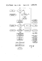
- FIG. 1 depicts the timing zones between two successive R waves of a tachycardia episode
- FIG. 2 depicts a plot of effective refractory period versus tachycardia cycle length, i.e., the physiological relationship discussed above which is used to determine the pacing intervals;
- FIG. 3 depicts the last two R waves of a tachycardia episode, followed by the pacing pulses during the phase A and phase B sequences;
- FIG. 4 depicts a pacer constructed in accordance with the principles of our invention
- FIG. 5 is a state diagram which characterizes the method of our invention.
- FIGS. 6-12 are flow charts which depict the method of our invention as implemented in the pacer of FIG. 4.
- the refractory zone is that in which a pacing pulse will have no effect on the heart tissue; following depolarization, the tissue must repolarize before an electrical stimulus has any effect on it.
- the termination zone is the only region in which a stimulus is likely to terminate a tachycardia episode.
- a pulse falling in the reset zone will not generally terminate the episode, although it will introduce a single, short interval followed by the original tachycardia interval, thus "resetting” or "advancing" the tachycardia.
- a pacing pulse falling in the collision zone will produce what is known as a fusion beat but will not otherwise affect the tachycardia.
- FIG. 2 depicts the physiological relationship between effective refractory period and tachycardia cycle length.
- the curve obviously varies from patient to patient.
- any pacemaker operated in accordance with the principles of our invention should be programmed to reflect the plot applicable to the particular patient.
- the "average" is used in the practice of our invention.
- the effective refractory period can be determined from the plot. If the pacing interval is then made slightly longer than the effective refractory period, the first pacing pulse will fall just outside the refractory zone, and thus termination of the tachycardia episode with maximum speed is facilitated.
- the plot of FIG. 2 represents the predetermined function referred to above.
- the plot of FIG. 2 can be determined as follows. A number of representative patients are selected. It is possible to select several different patient groups and to develop an "average" plot or function for each group or type of patient, and then preprogram the pacer of a particular patient in accordance with the plot for the patient group which represents the closest match. In any event, each patient in the sample group is paced at many different tachycardia rates. For each rate, the last pacing interval in the sequence is scanned to determine the effective refractory interval for that rate.
- the pacing interval which is pre-programmed or computed based on the plot of FIG. 2 is slightly greater, e.g., 30 milliseconds, than the mean value which is shown.
- the pacing interval which is computed is slightly greater, e.g., 30 milliseconds, than the mean value which is shown.
- FIG. 3 Before actually describing the pacer and method of our invention, it will be helpful to appreciate the two phases of the pacing as depicted in FIG. 3.
- two R waves At the left of FIG. 3 are shown two R waves, the last two of the several used to confirm a tachycardia episode.
- the number of pacing pulses is variable, as will be described below, but all pacing intervals in phase A in the preferred embodiment of the invention are equal.
- the selected interval based on the predetermined function represented in FIG. 2, not only applies to all pulses which are generated in phase A, but also to the spacing between the last R wave and the first pacing pulse.
- phase B pacing the pacing intervals gradually lengthen, ultimately merging into standby pacing as will be described in detail below.
- the pacer of our invention is shown in FIG. 4. It consists of conventional blocks and sub-blocks commonly used in digital systems and especially in those under microprocessor control.
- Block 10, containing the Programmable Data includes a number of latches and counters, all to be discussed below.
- the Tachy Detect block 12 is used in the process of confirming the existence of a tachycardia episode. The block measures the time interval between successive heartbeats and determines whether the interval is less than a prescribed limit which is stored in the programmable data block 10.
- the Standby Pacing block 14 controls conventional standby pacing, and the Pace Timing block 16 controls the inter-pulse intervals in phase-A and phase-B pacing.
- Sense Module block 18 is a conventional circuit for sensing a P wave or an R wave. When a signal is sensed, the sense output line is energized. Following the generation of a corresponding pacing pulse, the blank input line is energized to inhibit operation of the Sense Module, a feature well known in the pacing art.
- the Pace Module 20 is a conventional pulse generator, triggered by a signal applied to its pace input. The Sense and Pace Modules have their respective input and output connected to the same electrode lead (not shown), with the pacemaker case serving as the indifferent lead as is conventional practice.
- the State Controller can be operated in each of the states depicted in FIG. 5: the reset state, or any of states ST0-ST6. Each state is associated with a particular task. A transition from one state to another depends upon the present state and the existence of a certain condition. For example, referring to FIG. 5, if the system is in state ST5 and the sinus rhythm condition is determined to exist, the system switches to state ST1.
- the State Controller is of conventional design, and includes three blocks: master clock 30, memory M2, and control logic 32.
- the control logic applies an address to the address input of the memory (random access), and when the read input of the memory is pulsed the data stored at the respective address is furnished to the control logic.
- the master clock controls all of the system timing in the usual fashion.
- the address furnished to memory M2 corresponds with the present system state.
- the data furnished back to the control logic represents all of the states which may be entered from the present state, together with the conditions which will control the respective sequencing. For example, referring to FIG. 5, when the system is in state ST2, the address applied on the address bus is associated with state ST2.
- the data which is read from memory M2 identifies three possible succeeding states, ST0, ST3 and ST5, together with the three respective input conditions which control the respective state transitions, C3 time-out, C2 time-out and QRS.
- the control logic waits for one of the three input conditions to occur, following which a transition is made to the new state.
- Master clock 30 operates at a 16-KHz rate.
- the control logic includes a set of dividers for deriving 4-millisecond and 8-millisecond clocks, the purpose of which will be described below.
- Block 10 includes 4 latches L1-L4 which store four programmable parameters.
- the latches are loaded by program valid detect circuit 34, a conventional pacer module.
- program valid detect circuit 34 a conventional pacer module.
- the program valid input of state controller 22 is pulsed to inform the state controller that valid program parameters have been sensed.
- the parameters are stored in the four latches.
- the only parameters shown in the system of FIG. 4 in block 10 are those required for an understanding of the present invention. Other parameters which are standard in the pacer art, such as pacing pulse width, sensitivity, etc. are not shown because they are not necessary for an understanding of the present invention.
- Latch L1 contains the minimum R--R interval (tachycardia cycle length) which is accepted as sinus rhythm. Nine bits are used for this purpose. Any inter-beat interval whose duration is less than the value stored in latch L1 is representative of a tachycardia episode. However, tachycardia is not confirmed until a predetermined number of these short inter-pulse intervals are sensed in succession.
- Latch L2 contains the number of consecutive R--R intervals which must be shorter than the tachycardia cycle length which is stored in latch L1 in order for the pacer to confirm tachycardia. Only four bits are required for latch L2 since rarely will there be a requirement to sense more than 15 rapid heartbeats in order to confirm tachycardia.
- Latch L3 is a four-bit latch which contains the number of pulses which are generated during phase-A pacing. Five such pulses are shown in FIG. 3, but up to 15 may be programmed.
- Latch L4 contains the "number of attempts", that is, the number of consecutive times that the pacer will try to revert a tachycardia episode if sinus rhythm does not occur. The latch has four bits, and thus at most fifteen attempts may be made to terminate tachycardia. In the illustrative embodiment of the invention, once the maximum number of attempts have been made, the pacer ceases to operate until it is reprogrammed.
- Each of these counters has loaded in it the data in the respective latch when the respective load input is pulsed.
- Each counter is a four-bit presettable binary down counter. The count in each counter is decremented when the respective clock input is pulsed. Similarly, when a counter is decremented down to zero, it energizes its respective time-out conductor to inform the State Controller.
- the time-out conductor of each counter is really what is known as a carry output. The time-out label is used because the pulsing of one of the conductors represents the end of a sequence.
- Latch L5 when its latch enable input is pulsed, simply has transferred to it the minimum R--R interval which is stored in latch L1.
- the output of latch L5 is applied to the B input of 9-bit comparator P1 in the Tachy Detect block 12.
- the reason that the output of latch L1 is not extended directly to the B input of the comparator is that by using latch L5 in an intermediate capacity, the pacer can actually be programmed without disrupting the current processing.
- the program valid detect circuit 34 may load a new minimum R--R interval in latch L1, the previous contents of the latch are stored in latch L5 so that the current processing may continue. It is only the next time that the latch enable input to latch L5 is pulsed that the new value will be used.
- the Tachy Detect block 12 is used to determine when a short inter-beat interval of a tachycardia episode has occurred.
- Counter C4 is a nine-bit binary up counter which is clocked at a 4-millisecond rate. The count of counter C4 thus represents the number of 4-millisecond intervals which have occurred following the last reset pulse.
- the latch enable input of latch L6 is pulsed when an R wave is sensed; the contents of counter C4 are transferred to latch L6 and the counter is then reset. Thus latch L6 represents the most recent R--R interval.
- the output of the latch is applied to the A input of comparator P1. If the value in latch L6 is less than the interval represented by latch L5, then the output of comparator P1 is energized, the output being labelled "tachy".
- counter C4 is not extended directly to the A input of the comparator. The reason for this is is that at the start of every R--R interval, counter C4 will represent a count which is always less than that stored in latch L5. It is only at the end of the R--R interval that a check is made to see whether the most recent R wave is too soon after the preceding one.
- counter C4 is clocked at 4-millisecond intervals, its accuracy in measuring the R--R interval is reduced as the R--R interval decreases. However, even for a heart rate as high as 300 beats per minute, the error is only about + or -2%, a value which is certainly acceptable.
- the Standby Pacing module 14 is used to determine whether the heart rate has fallen below a preset minimum value.
- the preset value in terms of standby interval, is stored in 9-bit latch L7. In the illustrative embodiment of the invention it is factory set, but the value could be programmable if desired.
- the preset value is applied to the A input of 9-bit comparator P2.
- the current count of counter C4 is applied to the B input of comparator P2. As long as the current count, representing the R--R interval in progress, is less than the standby interval stored in latch L7, the output of comparator P2, the standby lead, remains low.
- the standby lead goes high in potential to inform the State Controller that a heartbeat has not occurred for a number of milliseconds equal to the standby value. It is at this time that a pacing pulse is generated--not to terminate tachycardia, but rather to stimulate a heartbeat. Since counter C4 is clocked at 4-millisecond intervals and it includes nine stages, the maximum count which the counter can represent is 512 ⁇ 4 or 2048 milliseconds. This is equivalent to a heart rate of about 29 beats per minute, certainly a value which can accommodate all desired standby pacing rates.
- the output of latch L6 represents the R--R interval which preceded the last heartbeat.
- the output of the latch is applied to the address input of memory M1 in the Pace Timing block 16.
- a data value is applied to the input of counter C5.
- the memory stores pacing intervals, based upon the plot of FIG. 2.
- the address inputs represent the tachycardia cycle length values, at 25-millisecond intervals.
- the data output is the pacing interval which, as discussed above, is slightly greater than the corresponding effective refractory period.
- the initial pacing interval which is selected is that which will allow the first pacing pulse to be generated just following the effective refractory period. Since the effective refractory period is a predetermined function of the R--R interval, and the pacing interval is a function of the effective refractory period, the R--R interval can be used to access memory M1 to derive the pacing interval which should be used. The use of a memory in this fashion is a simple way of implementing the predetermined function.
- the pacing interval for memory M1 is loaded into counter C5 when its load input is pulsed by the State Controller.
- the state of the U/D (up/down) lead determines whether the count in counter C5 is incremented or decremented when its clock input is pulsed.
- Counter C6 is loaded from the count in counter C5 when the load input of counter C6 is pulsed.
- Counter C6 is decremented at 8-millisecond intervals when the 8-millisecond clock pulses are applied to its clock input. When the counter counts down to zero, it energizes its time-out conductor.
- the reset state is a conventional "power-on" state, but it is also the result of a master reset, for example, should a conventional pacer programmer program the pacer to stop functioning.
- a reset signal is sensed by the control logic, as indicated by the reset input in the left margin of FIG. 6, all clocking is stopped. Furthermore, the sense and pace modules 18, 20 are inhibited from operating. The pacer is turned off and the system enters state ST0.
- state ST0 the pacer waits until it is programmed.
- program valid line of FIG. 4 goes high, represented in FIG. 7 as a program valid input, several things take place.
- counter C4 is the counter which times R--R intervals.
- counter C1 is loaded with a count representing the number of consecutive short R--R intervals which must be sensed in order to confirm tachycardia.
- latch L5 is loaded, upon the pulsing by the State Controller of the latch enable line, with a count representing the minimum R--R interval which is considered to be sinus rhythm.
- a variable delta is used later on to keep track of the direction and degree of movement of the plot of FIG. 2 required to represent a new pacing interval as a function of the current tachycardia cycle length.
- the variable delta basically a count, is initialized in state ST0 following reprogramming.
- the sense module 18 is then switched on so that beating of the patient's heart can be detected. Also, the clocks are switched on although the only clock of importance at this time is the 4-millisecond clock which advances the count in counter C4 at 4-millisecond intervals in order to time the R--R intervals.
- state ST1 the function of the system is to sense heartbeats, i.e., QRS complexes (or R waves). There are really only two possibilities, one resulting in a transition to state ST2, and the other resulting in a transition to state ST6, as indicated on the state diagram of FIG. 5. If the predetermined number of consecutive fast heartbeats are sensed, otherwise known as tachycardia confirmation, the system switches to state ST2. As long as fast heartbeats are occurring, but before the number of such consecutive beats has reached the number contained in latch L2 of FIG. 4, the system simply continues to count, by decrementing counter C1, the number of fast heartbeats which have occurred.
- QRS complexes or R waves
- the other possibility is for a heartbeat not to be sensed for the standby interval, that is, the time period from the last heartbeat to exceed the standby interval which is represented in latch L7.
- the system switches to state ST6 so that a pacing pulse may be generated to cause the heart to beat.
- the pacer senses whether the heart is beating so fast that tachycardia has developed, or whether the heart is beating so slowly that a pacing pulse is required to stimulate it.
- the pacer waits until a QRS complex is sensed. As long as a heartbeat has not been sensed, the pacer tests whether the R--R interval in progress exceeds the standby interval. It does this by continuously comparing the count in counter C4 with the value stored in latch L7. As indicated in FIG. 8, the relevant "input" is the output of comparator P2. If the comparator output goes high, indicating that the R--R interval in progress exceeds the standby interval, the system switches to state ST6. As will become apparent below, in this state practically nothing happens other than the generation of a pacing pulse.
- comparator P2 If the output of comparator P2 does not go high, the system simply continues to check for the appearance of an R wave. Each time that the heart beats, the output of counter C4 is latched into latch L6. As indicated on FIG. 8, the latch enable input of latch L6 is energized. In this manner the most recent R--R interval is stored in the latch. Immediately thereafter, counter C4 is reset so that another R--R interval can be measured.
- latch L6 now representing the most recent R--R interval, a test is performed to see whether that interval is less than the "tachy" rate, that is, whether the R--R interval just measured is less than the interval represented in latch L5. If it is not, the output of comparator P1 remains low, and this is an indication that no action should be taken.
- the number of consecutive fast heartbeats which have been detected is represented by the decremented count in counter C1. If an R--R interval is sensed which is not long enough to be considered part of a tachycardia episode, counter C1 should be returned to its original count, the count represented by latch L2. For this reason, if the output of comparator P1 remains low, the load input to counter C1 is pulsed. The count in counter C1 is restored to the original value in latch L2 and the system continues to monitor heartbeats.
- the system examines the time-out output of counter C1. If the counter was previously decremented down to zero, the most recent fast heartbeat confirms the presence of a tachycardia episode. If, on the other hand, counter C1 has not timed out, its clock input is pulsed. This results in the decrementing of the count, after which the system returns to monitor heartbeats.
- latch L2 might be programmed to represent 8 fast heartbeats in order to confirm tachycardia.
- the read input of memory M1 is pulsed.
- the address input of the memory is derived from the output of latch L6, the latch output representing the most recent R--R interval.
- the memory is thus read and the data which is loaded into counter C5, with the pulsing of the load input of the counter, represents the pacing interval for the current tachycardia rate.
- the pacing interval which is read from memory M1 is a function only of the last R--R interval in the series which is used to confirm tachycardia.
- the pacing interval which is based upon the effective refractory period which itself is a predetermined function of the tachycardia cycle length, is in the illustrative embodiment of the invention a function only of the last R--R interval. It would be possible, however, to make the pacing interval a function of the average of all of the R--R intervals which make up the tachycardia confirmation process, although it is preferred that the last R--R interval control the pacing interval.
- counter C6 has its load input pulsed so that the same count (pacing interval) stored in counter C5 is stored in counter C6 as well.
- Counter C2 then has its load input pulsed so that the number stored in latch L3 is transferred to counter C2.
- the number thus stored in counter C2 represents the number of pulses in the first phase of the subsequent pacing.
- the load input of counter C3 is pulsed so that this counter represents the total number of attempts which should be made in order to terminate the tachycardia.
- the 8-millisecond clock input of counter C6 is pulsed at 8-millisecond intervals. That is what is meant in FIG. 8 by the step "start counter C6". The reason for doing this will become apparent below.
- the Pace Module 20 is turned on so that pacing pulses can be generated, although the pulses are actually generated at times to be described below.
- the system then makes a transition to state ST2, the state during which the pulses are actually generated in an attempt to terminate tachycardia. As shown on FIG. 5, it is the "tachy” condition which controls the state transition, the "tachy” condition being represented by time-out of counter C1. Similarly, on FIG. 8, an affirmative answer to the "tachy confirmed” question leads to the state transition.
- counter C3 On entering state ST2, counter C3 is decremented with the pulsing of the clock input of the counter. Since an attempt will now be made to terminate the tachycardia episode, the counter is decremented. As described above, after the maximum number of attempts have been made, without success, the system "gives up". This is indicated on the state diagram of FIG. 5 by a C3 time-out which returns the system to state ST0. Referring to FIG. 9, after counter C3 is decremented, its time-out output is examined. If a time-out has occurred, the system switches to state ST0, at which point it simply waits to be programmed. [This is not to exclude the possibility of a complete recycling in which case another entire sequence would be begun.]
- Counter C5 originally contains the pacing interval to be used in phase A pacing. At the end of the sequencing in state ST1, counter C6 was loaded with this same value. Counter C6 is now pulsed once every 8 milliseconds. The system waits until counter C6 times out. It will time out at the end of every pacing interval. (Counter C6 will be described below as being initialized prior to every pacing interval during phase A pacing.) As long as the system is waiting for the time-out, the sense module 18 checks to see whether an R wave takes place. As long as one does not, the system continues to wait for a time-out of counter C6.
- the pacing interval must be timed again so that the next pulse in the phase A sequence can be generated. All that is required for this is that counter C6 be loaded once again from counter C5, and all this takes is the pulsing of the load input of counter C6. Another pacing interval is timed automatically with the generation of the 8-millisecond clocks.
- counter C4 is reset. This counter measures R--R intervals, and since a heartbeat has (hopefully) taken place as a result of the pacing pulse, the counter must be reset.
- Counter C2 is then decremented with the pulsing of its clock input. This is the counter whose count is decremented to indicate that another pulse in the phase A sequence has been generated.
- the last step in the state ST2 processing is to examine whether the last pacing pulse in the phase A sequence has been generated, that is, whether a time-out of counter C2 has occurred. If it has not, the system continues to wait for the next time-out of counter C6 at which time the next pacing pulse in the phase A sequence will be generated. But if the last pulse in the phase A sequence has been generated, indicated by a time-out of counter C2, the system switches to state ST3 as indicated on both of FIGS. 5 and 9. It is in state ST3 that the phase B pulses of FIG. 3 are generated.
- phase B pacing is not required as part of the tachycardia termination process. Rather, the phase B pacing provides for a smooth transition in the rate of the heartbeats--from the fast rate controlled by the phase A pacing, up to the slower rate of a sinus rhythm or even that of standby pacing.
- counter C6 is loaded with the pacing interval in the usual way.
- state ST3 the system waits for a time-out of counter C6. While waiting for a time-out, heartbeats are still monitored. If a heartbeat is sensed, as indicated by a QRS input on FIG. 10, the system switches to state ST4.
- a heartbeat is sensed, as indicated by a QRS input on FIG. 10, the system switches to state ST4.
- the heart may be beating in sinus rhythm, or the tachycardia may not have been reverted (even though no unevoked response was sensed during the phase A pacing). It is even possible that the heart, although it beat this once, will not beat again on its own in which case standby pacing will be required. All of this will be sorted out in state ST4.
- comparator P2 continuously monitors the count in counter C4. It will be recalled that counter C4 was reset toward the end of the processing in state ST2. The last pacing pulse generated in the phase A sequence presumably stimulated a heartbeat, and counter C4 times an R--R interval in the usual way. If the output of comparator P2 goes high, to indicate that the R--R interval in process exceeds the standby interval stored in latch L7, the system switches to state ST6. This is the state, as described above, during which a pacing pulse is generated in order to stimulate the heart. If the standby interval has not been exceeded, the system simply continues to wait for the counter C6 time-out.
- a pulse in the phase B sequence is generated. It should be noted that counter C6 was initially loaded with the original pacing interval, so that the first pulse in the phase B sequence occurs after a pacing interval which is equal to the pacing interval of all of the pulses during the phase A sequence. It is of no moment whether this first pulse is considered to be part of the phase A pulsing or the phase B pulsing.
- the sense module is first blanked, after which the pace module is triggered.
- Counter C4 is then reset in the usual way since R--R interval timing is always required.
- the system then readies itself for the next pulse in the phase B sequence.
- the clock input of counter C5 is pulsed rapidly four times in succession while the U/D lead is held high to control an "up" count.
- Counter C5 is clocked at 16 kHz, or once every 62.5 microseconds, to ensure that the time taken to increase its count by 4 is minimal compared to the pacing interval.
- the load input of counter C6 is pulsed.
- This requires an extra 4 of the 8-millisecond clock pulses in order to achieve a time-out of counter C6. This means that the pacing intervals during phase B are successively longer by 32 milliseconds.
- the pacing interval in the phase B sequence will get so long that it will be the standby interval which will become dominant (shorter), in which case it will be the Standby Pacing module 14 which causes the sysem to enter state ST6 at which time a pacing pulse is generated.
- state ST4 The only way to reach state ST4 is by sensing a QRS complex while in state ST3.
- the system was in the process of generating phase B pulses when the heart beat on its own, i.e., an unevoked response was sensed. That could be due to the pacing interval having gotten so long that the heart, now beating in sinus rhythm, beat on its own before the next pacing pulse was generated. It is also possible, especially toward the start of the phase B pacing, that the heart beat on its own because the tachycardia episode had not been terminated.
- phase A pacing Even though there were no unevoked responses during phase A pacing, that is, all phase A pacing pulses captured the heart, the tachycardia episode may not have been terminated, in which case a QRS complex will be sensed as soon as a phase B pacing interval is longer than the tachycardia cycle length.
- the system can reach state ST5 only when a QRS complex is sensed during phase A pacing, as indicated on FIGS. 5 and 9. There is little question in this case, however, about what has happened. Since the sense amplifier is blanked with the generation of each pacing pulse, the sensing of a heartbeat must represent an unevoked response. This means that the pacing pulses are not capturing the heart, and it is highly unlikely that the tachycardia episode has been terminated. In all probability, the pacing interval is too short, i.e., shorter than the effective refractory period. What must be done in state ST5 is to increase the pacing interval. This is not to say that it is impossible for the tachycardia to have been reverted. On the contrary, the heart may be beating in sinus rhythm. Alternatively, it is even possible that the heart has stopped beating altogether, in which case standby pacing is required.
- phase A pacing If the system is in state ST5, it means that it never completed phase A pacing which, in turn, means that the most recent pacing pulse in a phase A sequence did not capture the heart. The pacing interval must therefore be increased. But if the system is in state ST4, it means that phase B pacing was taking place, and that no unevoked responses were sensed during the complete phase A pacing pulse sequence. Since the phase A pulses did capture the heart but were ineffective in terminating the tachycardia, the indications are that the pacing interval was too long. The first pacing pulse probably fell past the termination zone, rather than before it. It is for this reason that the pacing interval is decremented before phase A pacing is resumed.
- counter C4 is first reset when the system enters state ST4 or state ST5. At the end of the processing in both of states ST2 and ST3, a pacing pulse was generated or a heartbeat was sensed. As such, counter C4 is reset in order to time a new R--R interval
- Counter C1 is also loaded in preparation for another tachycardia confirmation process. It might be thought that there is no need to confirm tachycardia all over again, at least by the complete process of monitoring the full complement of fast heartbeats. Nevertheless, before taking any action it is preferable that the usual routine for confirming tachycardia be executed. There are no rigid rules which apply in all cases, and it is possible that a pulse which logically should not have terminated the tachycardia episode did so.
- tachycardia episode may not have been terminated, even a single pacing pulse may have completely changed its timing. That is why, in the preferred embodiment of the invention, it is not enough simply to increment or decrement the old pacing interval. What must be done is to determine a new pacing interval based on the latest R--R interval in the tachycardia confirmation process. That interval will be used to access memory M1 to determine the appropriate pacing interval for use in the next phase A pacing. It is that new pacing interval which will be incremented or decremented, as will be described below, since it is now known that the plot of FIG. 2 is no longer applicable and that the plot has effectively moved upward or downward on the vertical scale.
- the third step in the processing of FIG. 11A is to stop the 8-millisecond clock from decrementing counter C6.
- states ST4 and ST5 there are no pacing pulses generated. Rather, the system is set up for the generation of another pacing pulse in state ST6, or the generation of a phase A sequence in state ST2, or simple monitoring in state ST1.
- the fourth step in the processing of FIG. 11A is to inhibit pacing altogether.
- latch enable input of latch L6 is pulsed so that the latest R--R interval is latched.
- counter C4 is reset to start the timing of another R--R interval.
- the first R--R interval is ignored.
- the reason for this is that the first R--R interval after the generation of the last pacing pulse in a reversion sequence has been found not to be representative of a tachycardia episode.
- the first QRS event which is sensed in state ST4 or state ST5 is ignored. The system goes back and waits for another QRS event.
- the output of comparator P1 is examined in the usual way. If the output stays low to indicate that the R--R interval is greater than the minimum interval stored in latch L1, it is an indication that the heart is beating in sinus rhythm. In other words, the heartbeat rate is not fast enough to be representative of tachycardia and it is not slow enough to require standby pacing. This is what is meant by the "sinus rhythm" conditions of FIG. 5. Whether the system is in state ST4 or state ST5, a transition is made to state ST1 as indicated in the state diagram and in FIG. 11A.
- Counter C1 is examined to see if it has timed out. It will be recalled that counter C1 is loaded with the number originally contained in latch L2 at the start of the processing in state ST4 or state ST5. If the counter has not timed out, it is simply decremented and the system continues to monitor heartbeats. A single beat in sinus rhythm during this monitoring causes a transition to state ST1, and a single inter-beat interval which exceeds the standby interval causes a transition to state ST6.
- variable delta is decremented in state ST4 and incremented in state ST5. For example, suppose that in state ST2, while phase A pulses are being generated, an unevoked response is sensed. The pacing interval must be increased. The system transfers to state ST5 at which time delta is incremented from zero to one. (It is assumed this is the first pacing sequence after reprogramming and thus delta is zero.) This will cause the new pacing interval, after it is retrieved from memory M1 based on the most recent tachycardia cycle length, to be increased to reflect the fact that the plot of FIG. 2 must have moved upward.
- the confirmation of tachycardia once the system has finished with phase A pacing and is engaged in phase B pacing is an indication that the new pacing interval, based on the most recent tachycardia cycle length, should be decreased because the plot of FIG. 2 must have shifted downward.
- delta is decremented; this will cause a reduction in the pacing interval used in the subsequent phase A sequence after the system transitions to state ST2.
- continued cycling in the order ST2, ST3, ST4, ST2, . . . will result in successive values for delta of 0, -1, -2, . . . .
- counter C5 is loaded from memory M1 with a new pacing interval which corresponds to the last measured R--R interval. This is accomplished by pulsing the read input of the memory and the load input of the counter in the usual fashion. It is then that counter C5, representing the new pacing interval, is incremented or decremented depending on the current sign of delta. This is controlled by applying the appropriate potential level to the U/D (up/down) input of counter C5. Depending on the potential of this conductor, the counter is either incremented or decremented when its clock input is pulsed. The clock input is pulsed a number of times equal to the magnitude of delta. Once the adjusted pacing interval is set, counter C6 is loaded with it from counter C5. The clock input of counter C6 is then started so that the first pacing interval may be timed.
- phase A pulses may be generated. Since the tachycardia episode persists, another pacing pulse sequence is required.
- the first processing in state ST2 is the decrementing of clock C3 and then the checking whether the maximum number of attempts at terminating the tachycardia have already been made. It is only after the tachycardia has been terminated, and the system ultimately finds itself in state ST1, that counter C3 is loaded from latch L4 so that the maximum number of attempts may be made once again the next time that tachycardia is confirmed.
- state ST6 As mentioned above, practically the only thing that happens in state ST6 is that a single pacing pulse is generated following the current R--R interval exceeding the standby interval. Before the pacing pulse is generated, as indicated on FIG. 12, the input of the sense module is blanked, typically for 100 milliseconds, so that only unevoked responses will be sensed by the sense amplifier. After pacing, the system switches to state ST1 where the cycle begins all over again with the monitoring of heartbeats.
Abstract
Description
Claims (122)
Priority Applications (4)
| Application Number | Priority Date | Filing Date | Title |
|---|---|---|---|
| US06/693,592 US4587970A (en) | 1985-01-22 | 1985-01-22 | Tachycardia reversion pacer |
| EP86300438A EP0189320B1 (en) | 1985-01-22 | 1986-01-22 | Tachycardia reversion pacer |
| AT86300438T ATE83385T1 (en) | 1985-01-22 | 1986-01-22 | PACEMAKER TO TERMINATE TACHYCARDIA. |
| DE8686300438T DE3687280T2 (en) | 1985-01-22 | 1986-01-22 | HEART PACER TO END A TACHYCARDIE. |
Applications Claiming Priority (1)
| Application Number | Priority Date | Filing Date | Title |
|---|---|---|---|
| US06/693,592 US4587970A (en) | 1985-01-22 | 1985-01-22 | Tachycardia reversion pacer |
Publications (1)
| Publication Number | Publication Date |
|---|---|
| US4587970A true US4587970A (en) | 1986-05-13 |
Family
ID=24785300
Family Applications (1)
| Application Number | Title | Priority Date | Filing Date |
|---|---|---|---|
| US06/693,592 Expired - Lifetime US4587970A (en) | 1985-01-22 | 1985-01-22 | Tachycardia reversion pacer |
Country Status (4)
| Country | Link |
|---|---|
| US (1) | US4587970A (en) |
| EP (1) | EP0189320B1 (en) |
| AT (1) | ATE83385T1 (en) |
| DE (1) | DE3687280T2 (en) |
Cited By (165)
| Publication number | Priority date | Publication date | Assignee | Title |
|---|---|---|---|---|
| US4788980A (en) * | 1986-07-18 | 1988-12-06 | Siemens-Pacesetter, Inc. | Pacemaker having PVC response and PMT terminating features |
| US4998974A (en) * | 1990-01-05 | 1991-03-12 | Telectronics Pacing Systems, Inc. | Apparatus and method for antitachycardia pacing in dual chamber arrhythmia control system |
| US5086772A (en) * | 1990-07-30 | 1992-02-11 | Telectronics Pacing Systems, Inc. | Arrhythmia control system employing arrhythmia recognition algorithm |
| US5176137A (en) * | 1991-03-01 | 1993-01-05 | Medtronic, Inc. | Apparatus for discrimination of stable and unstable ventricular tachycardia and for treatment thereof |
| US5193535A (en) * | 1991-08-27 | 1993-03-16 | Medtronic, Inc. | Method and apparatus for discrimination of ventricular tachycardia from ventricular fibrillation and for treatment thereof |
| US5243980A (en) * | 1992-06-30 | 1993-09-14 | Medtronic, Inc. | Method and apparatus for discrimination of ventricular and supraventricular tachycardia |
| US5257621A (en) * | 1991-08-27 | 1993-11-02 | Medtronic, Inc. | Apparatus for detection of and discrimination between tachycardia and fibrillation and for treatment of both |
| US5275621A (en) * | 1992-04-13 | 1994-01-04 | Medtronic, Inc. | Method and apparatus for terminating tachycardia |
| US5292338A (en) * | 1992-07-30 | 1994-03-08 | Medtronic, Inc. | Atrial defibrillator employing transvenous and subcutaneous electrodes and method of use |
| US5312441A (en) * | 1992-04-13 | 1994-05-17 | Medtronic, Inc. | Method and apparatus for discrimination of ventricular tachycardia from supraventricular tachycardia and for treatment thereof |
| US5314430A (en) * | 1993-06-24 | 1994-05-24 | Medtronic, Inc. | Atrial defibrillator employing transvenous and subcutaneous electrodes and method of use |
| US5330508A (en) * | 1993-03-02 | 1994-07-19 | Medtronic, Inc. | Apparatus for detection and treatment of tachycardia and fibrillation |
| US5342402A (en) * | 1993-01-29 | 1994-08-30 | Medtronic, Inc. | Method and apparatus for detection and treatment of tachycardia and fibrillation |
| US5344430A (en) * | 1991-11-20 | 1994-09-06 | Medtronic, Inc. | Method and apparatus for termination of ventricular tachycardia and ventricular fibrillation |
| US5354316A (en) * | 1993-01-29 | 1994-10-11 | Medtronic, Inc. | Method and apparatus for detection and treatment of tachycardia and fibrillation |
| US5383909A (en) * | 1993-01-29 | 1995-01-24 | Medtronic, Inc. | Diagnostic telemetry system for an apparatus for detection and treatment of tachycardia and fibrillation |
| US5403352A (en) * | 1993-11-23 | 1995-04-04 | Medtronic, Inc. | Method and apparatus for detection and treatment of tachycardia and fibrillation |
| US5447519A (en) * | 1994-03-19 | 1995-09-05 | Medtronic, Inc. | Method and apparatus for discrimination of monomorphic and polymorphic arrhythmias and for treatment thereof |
| US5545186A (en) * | 1995-03-30 | 1996-08-13 | Medtronic, Inc. | Prioritized rule based method and apparatus for diagnosis and treatment of arrhythmias |
| US5549642A (en) * | 1994-08-19 | 1996-08-27 | Medtronic, Inc. | Atrial defibrillator and method of use |
| US5601609A (en) * | 1993-09-15 | 1997-02-11 | Pacesetter, Inc. | Implantable cardiac stimulating device and method for administering synchronized cardioversion shock therapy to provide preemptive depolarization |
| EP0759311A2 (en) | 1995-08-17 | 1997-02-26 | Medtronic, Inc. | Multiple therapy cardiac assist device having battery voltage safety monitor |
| EP0759312A2 (en) | 1995-08-17 | 1997-02-26 | Medtronic, Inc. | Cardiac assist device |
| WO1997011745A1 (en) * | 1995-09-29 | 1997-04-03 | Medtronic, Inc. | Modification of pacemaker tachy response based on ffrw sensing |
| US5620471A (en) * | 1995-06-16 | 1997-04-15 | Pacesetter, Inc. | System and method for discriminating between atrial and ventricular arrhythmias and for applying cardiac therapy therefor |
| US5630834A (en) * | 1995-05-03 | 1997-05-20 | Medtronic, Inc. | Atrial defibrillator with means for delivering therapy in response to a determination that the patient is likely asleep |
| US5658320A (en) * | 1995-09-29 | 1997-08-19 | Medtronic, Inc. | Atrial tachyarrhythmia detection in implantable pulse generators |
| US5690686A (en) * | 1996-04-30 | 1997-11-25 | Medtronic, Inc. | Atrial defibrillation method |
| US5725561A (en) * | 1995-06-09 | 1998-03-10 | Medtronic, Inc. | Method and apparatus for variable rate cardiac stimulation |
| US5755736A (en) * | 1996-05-14 | 1998-05-26 | Medtronic, Inc. | Prioritized rule based method and apparatus for diagnosis and treatment of arrhythmias |
| WO1998025669A1 (en) | 1996-12-13 | 1998-06-18 | Medtronic, Inc. | Method and apparatus for diagnosis and treatment of arrhythmias |
| US5814083A (en) * | 1995-09-29 | 1998-09-29 | Medtronic, Inc | Pacemaker tachy determination based blocked on 2:1 sensing |
| US5836976A (en) * | 1997-04-30 | 1998-11-17 | Medtronic, Inc. | Cardioversion energy reduction system |
| US5836975A (en) * | 1996-12-19 | 1998-11-17 | Medtronic, Inc. | Method and apparatus for diagnosis and treatment of arrhythmias |
| WO1999008748A1 (en) | 1997-08-15 | 1999-02-25 | Medtronic, Inc. | Implantable medical device with automated last session identification |
| US5891043A (en) * | 1998-01-29 | 1999-04-06 | Medtronic, Inc. | Implantable medical device with automated last session identification |
| US5916237A (en) * | 1998-04-30 | 1999-06-29 | Medtronic, Inc. | Power control apparatus and method for a body implantable medical device |
| US5928271A (en) * | 1998-02-25 | 1999-07-27 | Medtronic, Inc. | Atrial anti-arrhythmia pacemaker and method using high rate atrial and backup ventricular pacing |
| US5973968A (en) * | 1998-04-30 | 1999-10-26 | Medtronic, Inc. | Apparatus and method for write protecting a programmable memory |
| US5987356A (en) * | 1997-06-05 | 1999-11-16 | Medtronic, Inc. | Method and apparatus for diagnosis and treatment of arrhythmias |
| US6058327A (en) * | 1998-07-09 | 2000-05-02 | Medtronic, Inc. | Implantable device with automatic sensing adjustment |
| US6081745A (en) * | 1998-08-17 | 2000-06-27 | Medtronic, Inc. | Method and apparatus for treatment of arrhythmias |
| US6091988A (en) * | 1998-04-30 | 2000-07-18 | Medtronic, Inc. | Apparatus for treating atrial tachyarrhythmias with synchronized shocks |
| US6091989A (en) * | 1998-04-08 | 2000-07-18 | Swerdlow; Charles D. | Method and apparatus for reduction of pain from electric shock therapies |
| US6091986A (en) * | 1998-04-27 | 2000-07-18 | Medtronic, Inc. | Method and apparatus for storage of physiologic signals |
| US6200265B1 (en) | 1999-04-16 | 2001-03-13 | Medtronic, Inc. | Peripheral memory patch and access method for use with an implantable medical device |
| US6223083B1 (en) | 1999-04-16 | 2001-04-24 | Medtronic, Inc. | Receiver employing digital filtering for use with an implantable medical device |
| US6249701B1 (en) | 1999-02-12 | 2001-06-19 | Medtronic, Inc. | Implantable device with automatic sensing adjustment |
| US6272380B1 (en) | 1999-08-19 | 2001-08-07 | Medtronic, Inc. | Apparatus for treating atrial tachy arrhythmias with synchronized shocks |
| US6295473B1 (en) | 1999-04-16 | 2001-09-25 | Medtronic, Inc. | Digital delay line receiver for use with an implantable medical device |
| US20010034539A1 (en) * | 2000-03-21 | 2001-10-25 | Stadler Robert W. | Method and apparatus for detection and treatment of tachycardia and fibrillation |
| US6330477B1 (en) | 1999-04-12 | 2001-12-11 | Medtronic, Inc. | Ventricular synchronized atrial pacing mode of implantable cardioverter/defibrillator |
| US6393316B1 (en) | 1999-05-12 | 2002-05-21 | Medtronic, Inc. | Method and apparatus for detection and treatment of cardiac arrhythmias |
| US6411851B1 (en) | 1999-11-04 | 2002-06-25 | Medtronic, Inc. | Implantable medical device programming apparatus having an auxiliary component storage compartment |
| US6442430B1 (en) | 2000-12-04 | 2002-08-27 | Medtronic, Inc. | Implantable medical device programmers having headset video and methods of using same |
| US6442429B1 (en) | 1999-06-18 | 2002-08-27 | Medtronic, Inc. | Method and apparatus for diagnosis and treatment of arrhythmias |
| US6445948B1 (en) | 1998-04-03 | 2002-09-03 | Medtronic, Inc. | Implantable medical device having a substantially flat battery |
| US6459566B1 (en) | 1998-06-24 | 2002-10-01 | Medtronic, Inc. | Implantable medical device having flat electrolytic capacitor with laser welded cover |
| US6470212B1 (en) | 1998-08-11 | 2002-10-22 | Medtronic, Inc. | Body heat powered implantable medical device |
| US6477420B1 (en) | 2001-04-27 | 2002-11-05 | Medtronic, Inc | Control of pacing rate in mode switching implantable medical devices |
| US20020188773A1 (en) * | 2001-04-30 | 2002-12-12 | Frederik Augustijn | Method and system for transferring and storing data in a medical device with limited storage and memory |
| US20020193695A1 (en) * | 2000-11-28 | 2002-12-19 | Koyrakh Lev A. | Automated template generation algorithm for implantable device |
| US6498951B1 (en) | 2000-10-13 | 2002-12-24 | Medtronic, Inc. | Implantable medical device employing integral housing for a formable flat battery |
| US6514195B1 (en) | 2000-04-28 | 2003-02-04 | Medtronic, Inc. | Ischemic heart disease detection |
| US6526311B2 (en) | 2000-08-11 | 2003-02-25 | Medtronic, Inc. | System and method for sensing and detecting far-field R-wave |
| US6567691B1 (en) | 2000-03-22 | 2003-05-20 | Medtronic, Inc. | Method and apparatus diagnosis and treatment of arrhythias |
| US6577896B2 (en) | 1998-05-07 | 2003-06-10 | Medtronic, Inc. | Single complex electrogram display having a sensing threshold for an implantable medical device |
| WO2003047690A2 (en) | 2001-12-03 | 2003-06-12 | Medtronic,Inc. | Dual chamber method and apparatus for diagnosis and treatment of arrhythmias |
| US6580946B2 (en) | 2001-04-26 | 2003-06-17 | Medtronic, Inc. | Pressure-modulated rate-responsive cardiac pacing |
| US20030125773A1 (en) * | 2001-12-03 | 2003-07-03 | Havel William J. | Control of arbitrary waveforms for constant delivered energy |
| US20030135242A1 (en) * | 2000-07-27 | 2003-07-17 | Mongeon Luc R. | Forced deceleration algorithm for synchronization of atrial cardioversion shock and technique for the implementation |
| US6595927B2 (en) | 2001-07-23 | 2003-07-22 | Medtronic, Inc. | Method and system for diagnosing and administering therapy of pulmonary congestion |
| US6609028B2 (en) | 2001-04-26 | 2003-08-19 | Medtronic, Inc. | PVC response-triggered blanking in a cardiac pacing system |
| US6636762B2 (en) | 2001-04-30 | 2003-10-21 | Medtronic, Inc. | Method and system for monitoring heart failure using rate change dynamics |
| US20030199936A1 (en) * | 2002-04-22 | 2003-10-23 | Struble Chester L. | Atrioventricular delay adjustment |
| US20030199934A1 (en) * | 2002-04-22 | 2003-10-23 | Chester Struble | Cardiac resynchronization with adaptive A1-A2 and/or V1-V2 intervals |
| US20030199957A1 (en) * | 2002-04-22 | 2003-10-23 | Chester Struble | Organizing data according to cardiac rhythm type |
| US20030199956A1 (en) * | 2002-04-22 | 2003-10-23 | Struble Chester L. | Cardiac output measurement using dual oxygen sensors in right and left ventricles |
| US20030199779A1 (en) * | 2002-04-22 | 2003-10-23 | Lambert Muhlenberg | Estimation of stroke volume cardiac output using an intracardiac pressure sensor |
| US20030204208A1 (en) * | 2002-04-25 | 2003-10-30 | Berthold Kramm | Ventricular safety pacing in biventricular pacing |
| US20030204140A1 (en) * | 2002-04-25 | 2003-10-30 | Bozidar Ferek-Patric | Ultrasound methods and implantable medical devices using same |
| US6650938B2 (en) | 2001-04-27 | 2003-11-18 | Medtronic, Inc. | Method and system for preventing atrial fibrillation by rapid pacing intervention |
| US6650941B2 (en) | 2000-12-22 | 2003-11-18 | Medtronic, Inc. | Implantable medical device programming wands having integral input device |
| US6658293B2 (en) | 2001-04-27 | 2003-12-02 | Medtronic, Inc. | Method and system for atrial capture detection based on far-field R-wave sensing |
| US20030233130A1 (en) * | 2002-06-14 | 2003-12-18 | Vasant Padmanabhan | Method and apparatus for prevention of arrhythmia clusters using overdrive pacing |
| US6671549B2 (en) | 2001-11-16 | 2003-12-30 | Medtronic, Inc. | Pacemaker utilizing QT dynamics to diagnose heart failure |
| US6675044B2 (en) | 2001-05-07 | 2004-01-06 | Medtronic, Inc. | Software-based record management system with access to time-line ordered clinical data acquired by an implanted device |
| US6678559B1 (en) | 1999-03-23 | 2004-01-13 | Medtronic, Inc. | Implantable medical device having a capacitor assembly with liner |
| US20040019367A1 (en) * | 2002-07-25 | 2004-01-29 | Roger Dahl | Apparatus and method for transmitting an electrical signal in an implantable medical device |
| US6695790B2 (en) | 2001-10-26 | 2004-02-24 | Medtronic, Inc. | Method and system for determining kidney failure |
| US6721599B2 (en) | 2001-11-16 | 2004-04-13 | Medtronic, Inc. | Pacemaker with sudden rate drop detection based on QT variations |
| US6745068B2 (en) | 2000-11-28 | 2004-06-01 | Medtronic, Inc. | Automated template generation algorithm for implantable device |
| US20040106956A1 (en) * | 2002-12-02 | 2004-06-03 | Vinod Sharma | Apparatus and method using ATP return cycle length for arrhythmia discrimination |
| US6748270B2 (en) | 2001-04-27 | 2004-06-08 | Medtronic Inc. | Method and system for nodal rhythm detection and treatment |
| US20040138715A1 (en) * | 2003-01-13 | 2004-07-15 | Van Groeningen Christianus J.J.E. | Synchronized atrial anti-tachy pacing system and method |
| US6792308B2 (en) | 2000-11-17 | 2004-09-14 | Medtronic, Inc. | Myocardial performance assessment |
| US20040215238A1 (en) * | 2003-04-24 | 2004-10-28 | Van Dam Peter M. | Pacemaker with improved capability for detecting onset of tachyarrhythmias and heart failure |
| US20040215275A1 (en) * | 2003-04-24 | 2004-10-28 | Vonk Bernardus F. M. | Intracardiac polarization signal stabilization |
| US20040220624A1 (en) * | 2003-04-30 | 2004-11-04 | Medtronic, Inc. | Method for elimination of ventricular pro-arrhythmic effect caused by atrial therapy |
| US20040216988A1 (en) * | 2003-04-29 | 2004-11-04 | Rogier Receveur | Multi-stable micro electromechanical switches and methods of fabricating same |
| US20040220623A1 (en) * | 2003-04-30 | 2004-11-04 | Medtronic, Inc. | Configurable cardioversion and defibrillation therapies in the presence of coexisting atrial and ventricular arrhythmia |
| US20040220634A1 (en) * | 2003-04-30 | 2004-11-04 | Medtronic, Inc. | History-dependent pacing interval determination for antitachycardia pacing |
| US6836682B2 (en) | 2001-11-16 | 2004-12-28 | Medtronic, Inc. | Rate responsive pacing system with QT sensor based on intrinsic QT data |
| US20050043764A1 (en) * | 2003-01-06 | 2005-02-24 | Willem Wesselink | Synchronous pacemaker with AV interval optimization |
| US6873870B2 (en) | 2001-04-30 | 2005-03-29 | Medtronic, Inc. | Methods for adjusting cardiac detection criteria and implantable medical devices using same |
| US20050080347A1 (en) * | 2003-10-10 | 2005-04-14 | Medtronic, Inc. | Method and apparatus for detecting and discriminating arrhythmias |
| US20050090871A1 (en) * | 2003-10-24 | 2005-04-28 | Cho Yong K. | Implantable medical device and method for delivering therapy for sleep-disordered breathing |
| US6889078B2 (en) | 2001-04-26 | 2005-05-03 | Medtronic, Inc. | Hysteresis activation of accelerated pacing |
| US20050103351A1 (en) * | 2003-11-13 | 2005-05-19 | Stomberg Charles R. | Time syncrhonization of data |
| US20050115811A1 (en) * | 2003-10-28 | 2005-06-02 | Rogier Receveur | MEMs switching circuit and method for an implantable medical device |
| US20050137485A1 (en) * | 2003-12-03 | 2005-06-23 | Jian Cao | Method and apparatus for generating a template for arrhythmia detection and electrogram morphology classification |
| US20050209646A1 (en) * | 2004-03-19 | 2005-09-22 | Wanasek Kevin A | Method and apparatus for delivering multi-directional defibrillation waveforms |
| US20050209647A1 (en) * | 2004-03-19 | 2005-09-22 | Wanasek Kevin A | Method and apparatus for delivering multi-directional defibrillation waveforms |
| US20050234519A1 (en) * | 2004-04-15 | 2005-10-20 | Ziegler Paul D | Cardiac stimulation device and method for automatic lower pacing rate optimization |
| WO2005097259A1 (en) | 2004-03-31 | 2005-10-20 | Medtronic, Inc. | Fully inhibited dual chamber pacing mode |
| US20050245975A1 (en) * | 2004-04-15 | 2005-11-03 | Hettrick Douglas A | Method and apparatus for controlling delivery of pacing pulses in response to increased ectopic frequency |
| US20050267539A1 (en) * | 2000-12-21 | 2005-12-01 | Medtronic, Inc. | System and method for ventricular pacing with AV interval modulation |
| US20050288725A1 (en) * | 2004-06-29 | 2005-12-29 | Hettrick Douglas A | Combination of electrogram and intra-cardiac pressure to discriminate between fibrillation and tachycardia |
| US20060020293A1 (en) * | 2004-06-04 | 2006-01-26 | Medtronic, Inc. | High frequency atrial burst pacing for improved ventricular rate control during atrial arrhythmias |
| US20060064027A1 (en) * | 2004-09-21 | 2006-03-23 | Borowitz Lynn A | Implantable medical device with his-purkinje activity detection |
| US7027861B2 (en) | 2001-10-09 | 2006-04-11 | Medtronic, Inc. | Method and apparatus for affecting atrial defibrillation with bi-atrial pacing |
| US20060089677A1 (en) * | 2004-10-25 | 2006-04-27 | Casavant David A | Self limited rate response |
| US7058443B2 (en) | 2001-04-26 | 2006-06-06 | Medtronic, Inc. | Diagnostic features in biatrial and biventricular pacing systems |
| WO2006060704A1 (en) | 2004-12-03 | 2006-06-08 | Medtronic, Inc. | Use of mechanical restitution to predict hemodynamic response to a rapid ventricular rhythm |
| US20060122649A1 (en) * | 2004-12-03 | 2006-06-08 | Ghanem Raja N | Subcutaneous implantable cardioverter/defibrillator |
| US20060161205A1 (en) * | 2005-01-18 | 2006-07-20 | Mitrani Paul D | Method and apparatus for arrhythmia detection in a medical device |
| US20060167506A1 (en) * | 2005-01-21 | 2006-07-27 | Stoop Gustaaf A | Implantable medical device with ventricular pacing protocol |
| US20060167508A1 (en) * | 2005-01-21 | 2006-07-27 | Willem Boute | Implantable medical device with ventricular pacing protocol including progressive conduction search |
| US20060224193A1 (en) * | 2005-03-31 | 2006-10-05 | Hess Michael F | Delivery of CRT therapy during AT/AF termination |
| US20060224199A1 (en) * | 2005-03-31 | 2006-10-05 | Zeijlemaker Volkert A | System for waveform stimulation compensating electrode polarization |
| US20060270937A1 (en) * | 2001-04-25 | 2006-11-30 | Koyrakh Lev A | Automated Template Generation Algorithm for Implantable Device |
| US7174208B2 (en) | 2002-12-03 | 2007-02-06 | Medtronic, Inc. | Slow rise defibrillation waveforms to minimize stored energy for a pulse modulated circuit and maximize charge transfer to myocardial membrane |
| US7181272B2 (en) | 2002-04-22 | 2007-02-20 | Medtronic, Inc. | Cardiac restraint with electrode attachment sites |
| WO2006118852A3 (en) * | 2005-04-29 | 2007-08-23 | Medtronic Inc | Method and apparatus for detection of tachyarrhythmia using cycle lengths |
| US20070203523A1 (en) * | 2006-02-28 | 2007-08-30 | Betzold Robert A | Implantable medical device with adaptive operation |
| US20070219589A1 (en) * | 2006-01-20 | 2007-09-20 | Condie Catherine R | System and method of using AV conduction timing |
| US20070239037A1 (en) * | 2005-10-05 | 2007-10-11 | Stefano Ghio | Interventricular delay as a prognostic marker for reverse remodeling outcome from cardiac resynchronization therapy |
| WO2007130628A2 (en) | 2006-05-04 | 2007-11-15 | Cardiomems, Inc. | Implantable wireless sensor for in vivo pressure measurement and continuous output determination |
| US20070293900A1 (en) * | 2006-06-15 | 2007-12-20 | Sheldon Todd J | System and Method for Promoting Intrinsic Conduction Through Atrial Timing |
| US20070293898A1 (en) * | 2006-06-15 | 2007-12-20 | Sheldon Todd J | System and Method for Determining Intrinsic AV Interval Timing |
| US20070293897A1 (en) * | 2006-06-15 | 2007-12-20 | Sheldon Todd J | System and Method for Promoting Instrinsic Conduction Through Atrial Timing Modification and Calculation of Timing Parameters |
| US20070293899A1 (en) * | 2006-06-15 | 2007-12-20 | Sheldon Todd J | System and Method for Ventricular Interval Smoothing Following a Premature Ventricular Contraction |
| US20080027493A1 (en) * | 2006-07-31 | 2008-01-31 | Sheldon Todd J | System and Method for Improving Ventricular Sensing |
| US20080027492A1 (en) * | 2006-07-31 | 2008-01-31 | Sheldon Todd J | Rate Smoothing Pacing Modality with Increased Ventricular Sensing |
| US20080027490A1 (en) * | 2006-07-31 | 2008-01-31 | Sheldon Todd J | Pacing Mode Event Classification with Rate Smoothing and Increased Ventricular Sensing |
| US20080140162A1 (en) * | 2006-12-06 | 2008-06-12 | Medtronic, Inc. | Medical device programming safety |
| US20080147145A1 (en) * | 2002-10-31 | 2008-06-19 | Medtronic, Inc. | Failsafe programming of implantable medical devices |
| US7515958B2 (en) | 2006-07-31 | 2009-04-07 | Medtronic, Inc. | System and method for altering pacing modality |
| US7561913B2 (en) | 2003-04-30 | 2009-07-14 | Medtronic, Inc. | Automatic adjusting R-wave synchronization algorithm for atrial cardioversion and defibrillation |
| US7599740B2 (en) | 2000-12-21 | 2009-10-06 | Medtronic, Inc. | Ventricular event filtering for an implantable medical device |
| US20090259269A1 (en) * | 2008-04-09 | 2009-10-15 | Brown Mark L | Method and apparatus for detecting and treating tachyarrhythmias incorporating diagnostic/therapeutic pacing techniques |
| US7689281B2 (en) | 2006-07-31 | 2010-03-30 | Medtronic, Inc. | Pacing mode event classification with increased ventricular sensing |
| US7720537B2 (en) | 2006-07-31 | 2010-05-18 | Medtronic, Inc. | System and method for providing improved atrial pacing based on physiological need |
| US7725172B2 (en) | 2003-01-13 | 2010-05-25 | Medtronic, Inc. | T-wave alternans train spotter |
| US20100222839A1 (en) * | 2009-02-27 | 2010-09-02 | Medtronic, Inc. | System and method for conditional biventricular pacing |
| US20100222838A1 (en) * | 2009-02-27 | 2010-09-02 | Sweeney Michael O | System and method for conditional biventricular pacing |
| US20100222834A1 (en) * | 2009-02-27 | 2010-09-02 | Sweeney Michael O | System and method for conditional biventricular pacing |
| US7856269B2 (en) | 2006-07-31 | 2010-12-21 | Medtronic, Inc. | System and method for determining phsyiologic events during pacing mode operation |
| US8352034B2 (en) | 2011-02-18 | 2013-01-08 | Medtronic, Inc. | Medical device programmer with adjustable kickstand |
| US8532775B2 (en) | 2011-02-18 | 2013-09-10 | Medtronic, Inc. | Modular medical device programmer |
| US8750994B2 (en) | 2011-07-31 | 2014-06-10 | Medtronic, Inc. | Morphology-based discrimination algorithm based on relative amplitude differences and correlation of imprints of energy distribution |
| US9782596B2 (en) | 2003-06-11 | 2017-10-10 | Boston Scientific Neuromodulation Corporation | Server for communication with an implantable medical device |
| US9931509B2 (en) | 2000-12-21 | 2018-04-03 | Medtronic, Inc. | Fully inhibited dual chamber pacing mode |
| US10220213B2 (en) | 2015-02-06 | 2019-03-05 | Cardiac Pacemakers, Inc. | Systems and methods for safe delivery of electrical stimulation therapy |
| US11235163B2 (en) | 2017-09-20 | 2022-02-01 | Cardiac Pacemakers, Inc. | Implantable medical device with multiple modes of operation |
Families Citing this family (1)
| Publication number | Priority date | Publication date | Assignee | Title |
|---|---|---|---|---|
| US5129393A (en) * | 1990-08-14 | 1992-07-14 | Medtronic, Inc. | Dual chamber rate responsive pacemaker with variable refractory period |
Citations (28)
| Publication number | Priority date | Publication date | Assignee | Title |
|---|---|---|---|---|
| US3939844A (en) * | 1973-10-18 | 1976-02-24 | Michel Pequignot | Method and apparatus for stimulating a heart to eliminate rhythmic abnormalities, especially tachycardias |
| US3942534A (en) * | 1973-11-21 | 1976-03-09 | Kenneth Roy Allen | Device for terminating tachycardia |
| US4163451A (en) * | 1977-10-26 | 1979-08-07 | Cordis Corporation | Interactive method and digitally timed apparatus for cardiac pacing arrhythmia treatment |
| EP0003782A1 (en) * | 1978-02-22 | 1979-09-05 | Bayer Ag | Extrusion tyres and methods and apparatus for their manufacture |
| US4181133A (en) * | 1978-05-22 | 1980-01-01 | Arco Medical Products Company | Programmable tachycardia pacer |
| GB2026870A (en) * | 1978-07-20 | 1980-02-13 | Medtronic Inc | Body implantable pacemaker |
| GB2076655A (en) * | 1980-03-25 | 1981-12-09 | Telectronics Pty Ltd | Two-pulse Tachycardia Control Pacer |
| US4307725A (en) * | 1978-08-22 | 1981-12-29 | Watfort Limited | Apparatus for tachycardia investigation or control |
| US4384585A (en) * | 1981-03-06 | 1983-05-24 | Medtronic, Inc. | Synchronous intracardiac cardioverter |
| EP0081209A1 (en) * | 1981-12-04 | 1983-06-15 | Siemens-Elema AB | Device for arresting tachycardia |
| US4388927A (en) * | 1979-12-13 | 1983-06-21 | American Hospital Supply Corporation | Programmable digital cardiac pacer |
| EP0087756A2 (en) * | 1982-02-26 | 1983-09-07 | Siemens Aktiengesellschaft | AV-sequential heart pacemaker |
| US4407289A (en) * | 1981-03-23 | 1983-10-04 | Telectronics Pty. Ltd. | Externally-reset tachycardia control pacer |
| US4421114A (en) * | 1978-10-30 | 1983-12-20 | Berkovits Barouh V | Tachycardia treatment |
| US4427011A (en) * | 1982-03-18 | 1984-01-24 | Telectronics Pty. Ltd. | Tachycardia control pacer with improved detection of tachycardia termination |
| US4429697A (en) * | 1982-04-12 | 1984-02-07 | Telectronics Pty. Ltd. | Dual chamber heart pacer with improved ventricular rate control |
| US4452248A (en) * | 1981-10-13 | 1984-06-05 | Keller Jr J Walter | Bidirectional pacemaker |
| EP0113176A1 (en) * | 1982-11-22 | 1984-07-11 | Intermedics, Inc. | Microprocessor controlled cardiac pacemaker for avoiding pacer sustained tachycardia |
| US4467810A (en) * | 1982-09-30 | 1984-08-28 | Cordis Corporation | Multi-mode microprocessor-based programmable cardiac pacer |
| US4473078A (en) * | 1982-05-24 | 1984-09-25 | Cardiac Resuscitator Corporation | Cardiac arrhythmia analysis system |
| US4485818A (en) * | 1980-11-14 | 1984-12-04 | Cordis Corporation | Multi-mode microprocessor-based programmable cardiac pacer |
| US4488554A (en) * | 1981-03-19 | 1984-12-18 | Telectronics Pty. Ltd. | Externally-inhibited tachycardia control pacer |
| US4488553A (en) * | 1981-03-19 | 1984-12-18 | Telectronics Pty. Ltd. | Externally controlled tachycardia control pacer |
| US4493325A (en) * | 1982-05-03 | 1985-01-15 | Medtronic, Inc. | Tachyarrhythmia pacer |
| US4515161A (en) * | 1984-01-10 | 1985-05-07 | Vitafin N.V. | Dual chamber pacemaker system with V-A time measurement apparatus and method |
| US4539991A (en) * | 1983-02-11 | 1985-09-10 | Vitafin N.V. | Dual chamber pacemaker |
| US4541430A (en) * | 1982-11-02 | 1985-09-17 | Siemens Aktiengesellschaft | Method and a heart pacemaker for terminating a tachycardia |
| US4543963A (en) * | 1983-11-22 | 1985-10-01 | Gessman Lawrence J | Method and apparatus for differentiating antegrade from retrograde P-waves and for preventing pacemaker generated tachycardia |
Family Cites Families (3)
| Publication number | Priority date | Publication date | Assignee | Title |
|---|---|---|---|---|
| US4312356A (en) * | 1979-03-07 | 1982-01-26 | George Edgar Sowton | Pacemakers for tachycardia control |
| DE3382604T2 (en) * | 1982-11-22 | 1993-01-07 | Intermedics Inc | HEART PACEMAKER. |
| US4554921A (en) * | 1983-02-11 | 1985-11-26 | Vitafin N.V. | Dual chamber pacemaker with automatic high rate limit mode determination |
-
1985
- 1985-01-22 US US06/693,592 patent/US4587970A/en not_active Expired - Lifetime
-
1986
- 1986-01-22 DE DE8686300438T patent/DE3687280T2/en not_active Revoked
- 1986-01-22 AT AT86300438T patent/ATE83385T1/en not_active IP Right Cessation
- 1986-01-22 EP EP86300438A patent/EP0189320B1/en not_active Revoked
Patent Citations (28)
| Publication number | Priority date | Publication date | Assignee | Title |
|---|---|---|---|---|
| US3939844A (en) * | 1973-10-18 | 1976-02-24 | Michel Pequignot | Method and apparatus for stimulating a heart to eliminate rhythmic abnormalities, especially tachycardias |
| US3942534A (en) * | 1973-11-21 | 1976-03-09 | Kenneth Roy Allen | Device for terminating tachycardia |
| US4163451A (en) * | 1977-10-26 | 1979-08-07 | Cordis Corporation | Interactive method and digitally timed apparatus for cardiac pacing arrhythmia treatment |
| EP0003782A1 (en) * | 1978-02-22 | 1979-09-05 | Bayer Ag | Extrusion tyres and methods and apparatus for their manufacture |
| US4181133A (en) * | 1978-05-22 | 1980-01-01 | Arco Medical Products Company | Programmable tachycardia pacer |
| GB2026870A (en) * | 1978-07-20 | 1980-02-13 | Medtronic Inc | Body implantable pacemaker |
| US4307725A (en) * | 1978-08-22 | 1981-12-29 | Watfort Limited | Apparatus for tachycardia investigation or control |
| US4421114A (en) * | 1978-10-30 | 1983-12-20 | Berkovits Barouh V | Tachycardia treatment |
| US4388927A (en) * | 1979-12-13 | 1983-06-21 | American Hospital Supply Corporation | Programmable digital cardiac pacer |
| GB2076655A (en) * | 1980-03-25 | 1981-12-09 | Telectronics Pty Ltd | Two-pulse Tachycardia Control Pacer |
| US4485818A (en) * | 1980-11-14 | 1984-12-04 | Cordis Corporation | Multi-mode microprocessor-based programmable cardiac pacer |
| US4384585A (en) * | 1981-03-06 | 1983-05-24 | Medtronic, Inc. | Synchronous intracardiac cardioverter |
| US4488554A (en) * | 1981-03-19 | 1984-12-18 | Telectronics Pty. Ltd. | Externally-inhibited tachycardia control pacer |
| US4488553A (en) * | 1981-03-19 | 1984-12-18 | Telectronics Pty. Ltd. | Externally controlled tachycardia control pacer |
| US4407289A (en) * | 1981-03-23 | 1983-10-04 | Telectronics Pty. Ltd. | Externally-reset tachycardia control pacer |
| US4452248A (en) * | 1981-10-13 | 1984-06-05 | Keller Jr J Walter | Bidirectional pacemaker |
| EP0081209A1 (en) * | 1981-12-04 | 1983-06-15 | Siemens-Elema AB | Device for arresting tachycardia |
| EP0087756A2 (en) * | 1982-02-26 | 1983-09-07 | Siemens Aktiengesellschaft | AV-sequential heart pacemaker |
| US4427011A (en) * | 1982-03-18 | 1984-01-24 | Telectronics Pty. Ltd. | Tachycardia control pacer with improved detection of tachycardia termination |
| US4429697A (en) * | 1982-04-12 | 1984-02-07 | Telectronics Pty. Ltd. | Dual chamber heart pacer with improved ventricular rate control |
| US4493325A (en) * | 1982-05-03 | 1985-01-15 | Medtronic, Inc. | Tachyarrhythmia pacer |
| US4473078A (en) * | 1982-05-24 | 1984-09-25 | Cardiac Resuscitator Corporation | Cardiac arrhythmia analysis system |
| US4467810A (en) * | 1982-09-30 | 1984-08-28 | Cordis Corporation | Multi-mode microprocessor-based programmable cardiac pacer |
| US4541430A (en) * | 1982-11-02 | 1985-09-17 | Siemens Aktiengesellschaft | Method and a heart pacemaker for terminating a tachycardia |
| EP0113176A1 (en) * | 1982-11-22 | 1984-07-11 | Intermedics, Inc. | Microprocessor controlled cardiac pacemaker for avoiding pacer sustained tachycardia |
| US4539991A (en) * | 1983-02-11 | 1985-09-10 | Vitafin N.V. | Dual chamber pacemaker |
| US4543963A (en) * | 1983-11-22 | 1985-10-01 | Gessman Lawrence J | Method and apparatus for differentiating antegrade from retrograde P-waves and for preventing pacemaker generated tachycardia |
| US4515161A (en) * | 1984-01-10 | 1985-05-07 | Vitafin N.V. | Dual chamber pacemaker system with V-A time measurement apparatus and method |
Non-Patent Citations (6)
| Title |
|---|
| Dulk et al., "American Journal of Cardiology", vol. 52, 1983, pp. 731-738. |
| Dulk et al., American Journal of Cardiology , vol. 52, 1983, pp. 731 738. * |
| Kuck et al., "American Journal of Cardiology", vol. 54, 1984, pp. 550-554. |
| Kuck et al., American Journal of Cardiology , vol. 54, 1984, pp. 550 554. * |
| Spurrell et al., "American Journal of Cardiology", vol. 49, Mar. 1982, pp. 753-760. |
| Spurrell et al., American Journal of Cardiology , vol. 49, Mar. 1982, pp. 753 760. * |
Cited By (268)
| Publication number | Priority date | Publication date | Assignee | Title |
|---|---|---|---|---|
| US4788980A (en) * | 1986-07-18 | 1988-12-06 | Siemens-Pacesetter, Inc. | Pacemaker having PVC response and PMT terminating features |
| US4998974A (en) * | 1990-01-05 | 1991-03-12 | Telectronics Pacing Systems, Inc. | Apparatus and method for antitachycardia pacing in dual chamber arrhythmia control system |
| US5086772A (en) * | 1990-07-30 | 1992-02-11 | Telectronics Pacing Systems, Inc. | Arrhythmia control system employing arrhythmia recognition algorithm |
| US5176137A (en) * | 1991-03-01 | 1993-01-05 | Medtronic, Inc. | Apparatus for discrimination of stable and unstable ventricular tachycardia and for treatment thereof |
| US5193535A (en) * | 1991-08-27 | 1993-03-16 | Medtronic, Inc. | Method and apparatus for discrimination of ventricular tachycardia from ventricular fibrillation and for treatment thereof |
| US5257621A (en) * | 1991-08-27 | 1993-11-02 | Medtronic, Inc. | Apparatus for detection of and discrimination between tachycardia and fibrillation and for treatment of both |
| US5344430A (en) * | 1991-11-20 | 1994-09-06 | Medtronic, Inc. | Method and apparatus for termination of ventricular tachycardia and ventricular fibrillation |
| US5275621A (en) * | 1992-04-13 | 1994-01-04 | Medtronic, Inc. | Method and apparatus for terminating tachycardia |
| US5312441A (en) * | 1992-04-13 | 1994-05-17 | Medtronic, Inc. | Method and apparatus for discrimination of ventricular tachycardia from supraventricular tachycardia and for treatment thereof |
| US5243980A (en) * | 1992-06-30 | 1993-09-14 | Medtronic, Inc. | Method and apparatus for discrimination of ventricular and supraventricular tachycardia |
| US5292338A (en) * | 1992-07-30 | 1994-03-08 | Medtronic, Inc. | Atrial defibrillator employing transvenous and subcutaneous electrodes and method of use |
| US5342402A (en) * | 1993-01-29 | 1994-08-30 | Medtronic, Inc. | Method and apparatus for detection and treatment of tachycardia and fibrillation |
| US5354316A (en) * | 1993-01-29 | 1994-10-11 | Medtronic, Inc. | Method and apparatus for detection and treatment of tachycardia and fibrillation |
| US5383909A (en) * | 1993-01-29 | 1995-01-24 | Medtronic, Inc. | Diagnostic telemetry system for an apparatus for detection and treatment of tachycardia and fibrillation |
| US5330508A (en) * | 1993-03-02 | 1994-07-19 | Medtronic, Inc. | Apparatus for detection and treatment of tachycardia and fibrillation |
| US5314430A (en) * | 1993-06-24 | 1994-05-24 | Medtronic, Inc. | Atrial defibrillator employing transvenous and subcutaneous electrodes and method of use |
| US5601609A (en) * | 1993-09-15 | 1997-02-11 | Pacesetter, Inc. | Implantable cardiac stimulating device and method for administering synchronized cardioversion shock therapy to provide preemptive depolarization |
| US5464430A (en) * | 1993-11-23 | 1995-11-07 | Medtronic, Inc. | Method and apparatus for detection and treatment of tachycardia and fibrillation |
| US5403352A (en) * | 1993-11-23 | 1995-04-04 | Medtronic, Inc. | Method and apparatus for detection and treatment of tachycardia and fibrillation |
| US5447519A (en) * | 1994-03-19 | 1995-09-05 | Medtronic, Inc. | Method and apparatus for discrimination of monomorphic and polymorphic arrhythmias and for treatment thereof |
| US5549642A (en) * | 1994-08-19 | 1996-08-27 | Medtronic, Inc. | Atrial defibrillator and method of use |
| US5545186A (en) * | 1995-03-30 | 1996-08-13 | Medtronic, Inc. | Prioritized rule based method and apparatus for diagnosis and treatment of arrhythmias |
| US6487443B2 (en) | 1995-03-30 | 2002-11-26 | Medtronic, Inc. | Prioritized rule based method and apparatus for diagnosis and treatment of arrhythmias |
| US6731978B2 (en) | 1995-03-30 | 2004-05-04 | Medtronic, Inc. | Prioritized rule based method and apparatus for diagnosis and treatment of arrhythmias |
| US5630834A (en) * | 1995-05-03 | 1997-05-20 | Medtronic, Inc. | Atrial defibrillator with means for delivering therapy in response to a determination that the patient is likely asleep |
| US5725561A (en) * | 1995-06-09 | 1998-03-10 | Medtronic, Inc. | Method and apparatus for variable rate cardiac stimulation |
| US5620471A (en) * | 1995-06-16 | 1997-04-15 | Pacesetter, Inc. | System and method for discriminating between atrial and ventricular arrhythmias and for applying cardiac therapy therefor |
| EP0759311A2 (en) | 1995-08-17 | 1997-02-26 | Medtronic, Inc. | Multiple therapy cardiac assist device having battery voltage safety monitor |
| EP0759312A2 (en) | 1995-08-17 | 1997-02-26 | Medtronic, Inc. | Cardiac assist device |
| WO1997011745A1 (en) * | 1995-09-29 | 1997-04-03 | Medtronic, Inc. | Modification of pacemaker tachy response based on ffrw sensing |
| US5658320A (en) * | 1995-09-29 | 1997-08-19 | Medtronic, Inc. | Atrial tachyarrhythmia detection in implantable pulse generators |
| US5759196A (en) * | 1995-09-29 | 1998-06-02 | Medtronic, Inc. | Modification of pacemaker tachy response based on FFRW sensing |
| US5814083A (en) * | 1995-09-29 | 1998-09-29 | Medtronic, Inc | Pacemaker tachy determination based blocked on 2:1 sensing |
| EP1275413A1 (en) | 1995-09-29 | 2003-01-15 | Medtronic, Inc. | Pacemaker tachy determination based on blocked 2:1 sensing |
| EP1334746A1 (en) | 1995-09-29 | 2003-08-13 | Medtronic, Inc. | Pacemaker tachy determination based on blocked 2:1 sensing |
| US5690686A (en) * | 1996-04-30 | 1997-11-25 | Medtronic, Inc. | Atrial defibrillation method |
| US5755736A (en) * | 1996-05-14 | 1998-05-26 | Medtronic, Inc. | Prioritized rule based method and apparatus for diagnosis and treatment of arrhythmias |
| US6178350B1 (en) | 1996-05-14 | 2001-01-23 | Medtronic, Inc. | Prioritized rule based method and apparatus for diagnosis and treatment of arrhythmias |
| WO1998025669A1 (en) | 1996-12-13 | 1998-06-18 | Medtronic, Inc. | Method and apparatus for diagnosis and treatment of arrhythmias |
| US5836975A (en) * | 1996-12-19 | 1998-11-17 | Medtronic, Inc. | Method and apparatus for diagnosis and treatment of arrhythmias |
| US5836976A (en) * | 1997-04-30 | 1998-11-17 | Medtronic, Inc. | Cardioversion energy reduction system |
| US5987356A (en) * | 1997-06-05 | 1999-11-16 | Medtronic, Inc. | Method and apparatus for diagnosis and treatment of arrhythmias |
| WO1999008748A1 (en) | 1997-08-15 | 1999-02-25 | Medtronic, Inc. | Implantable medical device with automated last session identification |
| US6007493A (en) * | 1997-08-15 | 1999-12-28 | Medtronic, Inc. | Implanted automated last session identification |
| US5891043A (en) * | 1998-01-29 | 1999-04-06 | Medtronic, Inc. | Implantable medical device with automated last session identification |
| US5928271A (en) * | 1998-02-25 | 1999-07-27 | Medtronic, Inc. | Atrial anti-arrhythmia pacemaker and method using high rate atrial and backup ventricular pacing |
| US6445948B1 (en) | 1998-04-03 | 2002-09-03 | Medtronic, Inc. | Implantable medical device having a substantially flat battery |
| US6091989A (en) * | 1998-04-08 | 2000-07-18 | Swerdlow; Charles D. | Method and apparatus for reduction of pain from electric shock therapies |
| US6438418B1 (en) | 1998-04-08 | 2002-08-20 | Imperception, Incorporated | Method and apparatus for reduction of pain from electric shock therapies |
| US6091986A (en) * | 1998-04-27 | 2000-07-18 | Medtronic, Inc. | Method and apparatus for storage of physiologic signals |
| US5916237A (en) * | 1998-04-30 | 1999-06-29 | Medtronic, Inc. | Power control apparatus and method for a body implantable medical device |
| US5973968A (en) * | 1998-04-30 | 1999-10-26 | Medtronic, Inc. | Apparatus and method for write protecting a programmable memory |
| US6091988A (en) * | 1998-04-30 | 2000-07-18 | Medtronic, Inc. | Apparatus for treating atrial tachyarrhythmias with synchronized shocks |
| US6577896B2 (en) | 1998-05-07 | 2003-06-10 | Medtronic, Inc. | Single complex electrogram display having a sensing threshold for an implantable medical device |
| US6459566B1 (en) | 1998-06-24 | 2002-10-01 | Medtronic, Inc. | Implantable medical device having flat electrolytic capacitor with laser welded cover |
| US6058327A (en) * | 1998-07-09 | 2000-05-02 | Medtronic, Inc. | Implantable device with automatic sensing adjustment |
| US6470212B1 (en) | 1998-08-11 | 2002-10-22 | Medtronic, Inc. | Body heat powered implantable medical device |
| US6081745A (en) * | 1998-08-17 | 2000-06-27 | Medtronic, Inc. | Method and apparatus for treatment of arrhythmias |
| US6459932B1 (en) | 1998-08-17 | 2002-10-01 | Medtronic, Inc. | Method and apparatus for treatment of arrhythmias |
| US6249701B1 (en) | 1999-02-12 | 2001-06-19 | Medtronic, Inc. | Implantable device with automatic sensing adjustment |
| US6678559B1 (en) | 1999-03-23 | 2004-01-13 | Medtronic, Inc. | Implantable medical device having a capacitor assembly with liner |
| US6330477B1 (en) | 1999-04-12 | 2001-12-11 | Medtronic, Inc. | Ventricular synchronized atrial pacing mode of implantable cardioverter/defibrillator |
| US6200265B1 (en) | 1999-04-16 | 2001-03-13 | Medtronic, Inc. | Peripheral memory patch and access method for use with an implantable medical device |
| US6295473B1 (en) | 1999-04-16 | 2001-09-25 | Medtronic, Inc. | Digital delay line receiver for use with an implantable medical device |
| US6223083B1 (en) | 1999-04-16 | 2001-04-24 | Medtronic, Inc. | Receiver employing digital filtering for use with an implantable medical device |
| US6393316B1 (en) | 1999-05-12 | 2002-05-21 | Medtronic, Inc. | Method and apparatus for detection and treatment of cardiac arrhythmias |
| US6442429B1 (en) | 1999-06-18 | 2002-08-27 | Medtronic, Inc. | Method and apparatus for diagnosis and treatment of arrhythmias |
| US6272380B1 (en) | 1999-08-19 | 2001-08-07 | Medtronic, Inc. | Apparatus for treating atrial tachy arrhythmias with synchronized shocks |
| US6411851B1 (en) | 1999-11-04 | 2002-06-25 | Medtronic, Inc. | Implantable medical device programming apparatus having an auxiliary component storage compartment |
| US6879856B2 (en) | 2000-03-21 | 2005-04-12 | Medtronic, Inc. | Method and apparatus for detection and treatment of tachycardia and fibrillation |
| US20010034539A1 (en) * | 2000-03-21 | 2001-10-25 | Stadler Robert W. | Method and apparatus for detection and treatment of tachycardia and fibrillation |
| US6567691B1 (en) | 2000-03-22 | 2003-05-20 | Medtronic, Inc. | Method and apparatus diagnosis and treatment of arrhythias |
| US6514195B1 (en) | 2000-04-28 | 2003-02-04 | Medtronic, Inc. | Ischemic heart disease detection |
| US7369892B2 (en) | 2000-04-28 | 2008-05-06 | Medtronic, Inc. | Ischemic heart disease detection |
| US20030135242A1 (en) * | 2000-07-27 | 2003-07-17 | Mongeon Luc R. | Forced deceleration algorithm for synchronization of atrial cardioversion shock and technique for the implementation |
| US6988000B2 (en) | 2000-07-27 | 2006-01-17 | Medtronic, Inc. | Forced deceleration algorithm for synchronization of atrial cardioversion shock and technique for the implementation |
| US6526311B2 (en) | 2000-08-11 | 2003-02-25 | Medtronic, Inc. | System and method for sensing and detecting far-field R-wave |
| US6498951B1 (en) | 2000-10-13 | 2002-12-24 | Medtronic, Inc. | Implantable medical device employing integral housing for a formable flat battery |
| US6792308B2 (en) | 2000-11-17 | 2004-09-14 | Medtronic, Inc. | Myocardial performance assessment |
| US20020193695A1 (en) * | 2000-11-28 | 2002-12-19 | Koyrakh Lev A. | Automated template generation algorithm for implantable device |
| US6745068B2 (en) | 2000-11-28 | 2004-06-01 | Medtronic, Inc. | Automated template generation algorithm for implantable device |
| US7062315B2 (en) | 2000-11-28 | 2006-06-13 | Medtronic, Inc. | Automated template generation algorithm for implantable device |
| US6442430B1 (en) | 2000-12-04 | 2002-08-27 | Medtronic, Inc. | Implantable medical device programmers having headset video and methods of using same |
| US20050267539A1 (en) * | 2000-12-21 | 2005-12-01 | Medtronic, Inc. | System and method for ventricular pacing with AV interval modulation |
| US8060202B2 (en) | 2000-12-21 | 2011-11-15 | Medtronic, Inc. | Ventricular event filtering for an implantable medical device |
| US7599740B2 (en) | 2000-12-21 | 2009-10-06 | Medtronic, Inc. | Ventricular event filtering for an implantable medical device |
| US9931509B2 (en) | 2000-12-21 | 2018-04-03 | Medtronic, Inc. | Fully inhibited dual chamber pacing mode |
| US7738955B2 (en) | 2000-12-21 | 2010-06-15 | Medtronic, Inc. | System and method for ventricular pacing with AV interval modulation |
| US6650941B2 (en) | 2000-12-22 | 2003-11-18 | Medtronic, Inc. | Implantable medical device programming wands having integral input device |
| US20060270937A1 (en) * | 2001-04-25 | 2006-11-30 | Koyrakh Lev A | Automated Template Generation Algorithm for Implantable Device |
| US7640054B2 (en) | 2001-04-25 | 2009-12-29 | Medtronic, Inc. | Automated template generation algorithm for implantable device |
| US6609028B2 (en) | 2001-04-26 | 2003-08-19 | Medtronic, Inc. | PVC response-triggered blanking in a cardiac pacing system |
| US7058443B2 (en) | 2001-04-26 | 2006-06-06 | Medtronic, Inc. | Diagnostic features in biatrial and biventricular pacing systems |
| US6580946B2 (en) | 2001-04-26 | 2003-06-17 | Medtronic, Inc. | Pressure-modulated rate-responsive cardiac pacing |
| US6889078B2 (en) | 2001-04-26 | 2005-05-03 | Medtronic, Inc. | Hysteresis activation of accelerated pacing |
| US6477420B1 (en) | 2001-04-27 | 2002-11-05 | Medtronic, Inc | Control of pacing rate in mode switching implantable medical devices |
| US6650938B2 (en) | 2001-04-27 | 2003-11-18 | Medtronic, Inc. | Method and system for preventing atrial fibrillation by rapid pacing intervention |
| US6658293B2 (en) | 2001-04-27 | 2003-12-02 | Medtronic, Inc. | Method and system for atrial capture detection based on far-field R-wave sensing |
| US6748270B2 (en) | 2001-04-27 | 2004-06-08 | Medtronic Inc. | Method and system for nodal rhythm detection and treatment |
| US6636762B2 (en) | 2001-04-30 | 2003-10-21 | Medtronic, Inc. | Method and system for monitoring heart failure using rate change dynamics |
| US6873870B2 (en) | 2001-04-30 | 2005-03-29 | Medtronic, Inc. | Methods for adjusting cardiac detection criteria and implantable medical devices using same |
| US6910084B2 (en) | 2001-04-30 | 2005-06-21 | Medtronic, Inc | Method and system for transferring and storing data in a medical device with limited storage and memory |
| US20020188773A1 (en) * | 2001-04-30 | 2002-12-12 | Frederik Augustijn | Method and system for transferring and storing data in a medical device with limited storage and memory |
| US6675044B2 (en) | 2001-05-07 | 2004-01-06 | Medtronic, Inc. | Software-based record management system with access to time-line ordered clinical data acquired by an implanted device |
| US6595927B2 (en) | 2001-07-23 | 2003-07-22 | Medtronic, Inc. | Method and system for diagnosing and administering therapy of pulmonary congestion |
| US7027861B2 (en) | 2001-10-09 | 2006-04-11 | Medtronic, Inc. | Method and apparatus for affecting atrial defibrillation with bi-atrial pacing |
| US6695790B2 (en) | 2001-10-26 | 2004-02-24 | Medtronic, Inc. | Method and system for determining kidney failure |
| US6721599B2 (en) | 2001-11-16 | 2004-04-13 | Medtronic, Inc. | Pacemaker with sudden rate drop detection based on QT variations |
| US6671549B2 (en) | 2001-11-16 | 2003-12-30 | Medtronic, Inc. | Pacemaker utilizing QT dynamics to diagnose heart failure |
| US6836682B2 (en) | 2001-11-16 | 2004-12-28 | Medtronic, Inc. | Rate responsive pacing system with QT sensor based on intrinsic QT data |
| US20030144700A1 (en) * | 2001-12-03 | 2003-07-31 | Brown Mark L. | Dual chamber method and apparatus for diagnosis and treatment of arrhythmias |
| WO2003047690A2 (en) | 2001-12-03 | 2003-06-12 | Medtronic,Inc. | Dual chamber method and apparatus for diagnosis and treatment of arrhythmias |
| US20030125773A1 (en) * | 2001-12-03 | 2003-07-03 | Havel William J. | Control of arbitrary waveforms for constant delivered energy |
| US7031771B2 (en) | 2001-12-03 | 2006-04-18 | Medtronic, Inc. | Dual chamber method and apparatus for diagnosis and treatment of arrhythmias |
| US7151963B2 (en) | 2001-12-03 | 2006-12-19 | Medtronic, Inc. | Control of arbitrary waveforms for constant delivered energy |
| US7164948B2 (en) | 2002-04-22 | 2007-01-16 | Medtronic, Inc. | Cardiac output measurement using dual oxygen sensors in right and left ventricles |
| US20030199956A1 (en) * | 2002-04-22 | 2003-10-23 | Struble Chester L. | Cardiac output measurement using dual oxygen sensors in right and left ventricles |
| US20030199934A1 (en) * | 2002-04-22 | 2003-10-23 | Chester Struble | Cardiac resynchronization with adaptive A1-A2 and/or V1-V2 intervals |
| US7024244B2 (en) | 2002-04-22 | 2006-04-04 | Medtronic, Inc. | Estimation of stroke volume cardiac output using an intracardiac pressure sensor |
| US7181272B2 (en) | 2002-04-22 | 2007-02-20 | Medtronic, Inc. | Cardiac restraint with electrode attachment sites |
| US6882882B2 (en) | 2002-04-22 | 2005-04-19 | Medtronic, Inc. | Atrioventricular delay adjustment |
| US20030199957A1 (en) * | 2002-04-22 | 2003-10-23 | Chester Struble | Organizing data according to cardiac rhythm type |
| US20030199779A1 (en) * | 2002-04-22 | 2003-10-23 | Lambert Muhlenberg | Estimation of stroke volume cardiac output using an intracardiac pressure sensor |
| US20030199936A1 (en) * | 2002-04-22 | 2003-10-23 | Struble Chester L. | Atrioventricular delay adjustment |
| US6934586B2 (en) | 2002-04-22 | 2005-08-23 | Medtronic, Inc. | Cardiac resynchronization with adaptive A1-A2 and/or V1-V2 intervals |
| US7058450B2 (en) | 2002-04-22 | 2006-06-06 | Medtronic, Inc. | Organizing data according to cardiac rhythm type |
| US20030204140A1 (en) * | 2002-04-25 | 2003-10-30 | Bozidar Ferek-Patric | Ultrasound methods and implantable medical devices using same |
| US7037266B2 (en) | 2002-04-25 | 2006-05-02 | Medtronic, Inc. | Ultrasound methods and implantable medical devices using same |
| US6996437B2 (en) | 2002-04-25 | 2006-02-07 | Medtronic, Inc. | Ventricular safety pacing in biventricular pacing |
| US20030204208A1 (en) * | 2002-04-25 | 2003-10-30 | Berthold Kramm | Ventricular safety pacing in biventricular pacing |
| US20030233130A1 (en) * | 2002-06-14 | 2003-12-18 | Vasant Padmanabhan | Method and apparatus for prevention of arrhythmia clusters using overdrive pacing |
| US7076298B2 (en) | 2002-06-14 | 2006-07-11 | Medtronic, Inc. | Method and apparatus for prevention of arrhythmia clusters using overdrive pacing |
| US20040019367A1 (en) * | 2002-07-25 | 2004-01-29 | Roger Dahl | Apparatus and method for transmitting an electrical signal in an implantable medical device |
| US7027862B2 (en) | 2002-07-25 | 2006-04-11 | Medtronic, Inc. | Apparatus and method for transmitting an electrical signal in an implantable medical device |
| US20110125221A1 (en) * | 2002-10-31 | 2011-05-26 | Medtronic, Inc. | Failsafe programming of implantable medical devices |
| US9867992B2 (en) | 2002-10-31 | 2018-01-16 | Medtronic, Inc. | Failsafe programming of implantable medical devices |
| US7899546B2 (en) | 2002-10-31 | 2011-03-01 | Medtronic, Inc. | Failsafe programming of implantable medical devices |
| US20080147145A1 (en) * | 2002-10-31 | 2008-06-19 | Medtronic, Inc. | Failsafe programming of implantable medical devices |
| US20040106956A1 (en) * | 2002-12-02 | 2004-06-03 | Vinod Sharma | Apparatus and method using ATP return cycle length for arrhythmia discrimination |
| US7149577B2 (en) | 2002-12-02 | 2006-12-12 | Medtronic, Inc. | Apparatus and method using ATP return cycle length for arrhythmia discrimination |
| US7174208B2 (en) | 2002-12-03 | 2007-02-06 | Medtronic, Inc. | Slow rise defibrillation waveforms to minimize stored energy for a pulse modulated circuit and maximize charge transfer to myocardial membrane |
| US20050043764A1 (en) * | 2003-01-06 | 2005-02-24 | Willem Wesselink | Synchronous pacemaker with AV interval optimization |
| US7215998B2 (en) | 2003-01-06 | 2007-05-08 | Medtronic, Inc. | Synchronous pacemaker with AV interval optimization |
| US7725172B2 (en) | 2003-01-13 | 2010-05-25 | Medtronic, Inc. | T-wave alternans train spotter |
| US8175695B2 (en) | 2003-01-13 | 2012-05-08 | Medtronic, Inc. | T-wave alternans train spotter |
| US7162300B2 (en) | 2003-01-13 | 2007-01-09 | Medtronic, Inc. | Synchronized atrial anti-tachy pacing system and method |
| US20040138715A1 (en) * | 2003-01-13 | 2004-07-15 | Van Groeningen Christianus J.J.E. | Synchronized atrial anti-tachy pacing system and method |
| US20100145404A1 (en) * | 2003-01-13 | 2010-06-10 | Medtronic, Inc. | T-wave alternans train spotter |
| US7363078B2 (en) | 2003-04-24 | 2008-04-22 | Medtronic, Inc. | Intracardiac polarization signal stabilization |
| US20040215238A1 (en) * | 2003-04-24 | 2004-10-28 | Van Dam Peter M. | Pacemaker with improved capability for detecting onset of tachyarrhythmias and heart failure |
| US20040215275A1 (en) * | 2003-04-24 | 2004-10-28 | Vonk Bernardus F. M. | Intracardiac polarization signal stabilization |
| US7190245B2 (en) | 2003-04-29 | 2007-03-13 | Medtronic, Inc. | Multi-stable micro electromechanical switches and methods of fabricating same |
| US8111118B2 (en) | 2003-04-29 | 2012-02-07 | Medtronic, Inc. | Multi-stable micro electromechanical switches and methods of fabricating same |
| US7688166B2 (en) | 2003-04-29 | 2010-03-30 | Medtronic, Inc. | Multi-stable micro electromechanical switches and methods of fabricating same |
| US20040216988A1 (en) * | 2003-04-29 | 2004-11-04 | Rogier Receveur | Multi-stable micro electromechanical switches and methods of fabricating same |
| US20070009203A1 (en) * | 2003-04-29 | 2007-01-11 | Rogier Receveur | Multi-stable micro electromechanical switches and methods of fabricating same |
| US20040220624A1 (en) * | 2003-04-30 | 2004-11-04 | Medtronic, Inc. | Method for elimination of ventricular pro-arrhythmic effect caused by atrial therapy |
| US7561913B2 (en) | 2003-04-30 | 2009-07-14 | Medtronic, Inc. | Automatic adjusting R-wave synchronization algorithm for atrial cardioversion and defibrillation |
| US7536224B2 (en) | 2003-04-30 | 2009-05-19 | Medtronic, Inc. | Method for elimination of ventricular pro-arrhythmic effect caused by atrial therapy |
| US7177683B2 (en) | 2003-04-30 | 2007-02-13 | Medtronic, Inc. | History-dependent pacing interval determination for antitachycardia pacing |
| US20040220623A1 (en) * | 2003-04-30 | 2004-11-04 | Medtronic, Inc. | Configurable cardioversion and defibrillation therapies in the presence of coexisting atrial and ventricular arrhythmia |
| US20040220634A1 (en) * | 2003-04-30 | 2004-11-04 | Medtronic, Inc. | History-dependent pacing interval determination for antitachycardia pacing |
| US7313436B2 (en) | 2003-04-30 | 2007-12-25 | Medtronic, Inc. | Configurable cardioversion and defibrillation therapies in the presence of coexisting atrial and ventricular arrhythmia |
| WO2004098706A3 (en) * | 2003-04-30 | 2004-12-29 | Medtronic Inc | History-dependent pacing interval determination for antitachycardia pacing |
| WO2004098706A2 (en) * | 2003-04-30 | 2004-11-18 | Medtronic, Inc. | History-dependent pacing interval determination for antitachycardia pacing |
| US9782596B2 (en) | 2003-06-11 | 2017-10-10 | Boston Scientific Neuromodulation Corporation | Server for communication with an implantable medical device |
| US20050080347A1 (en) * | 2003-10-10 | 2005-04-14 | Medtronic, Inc. | Method and apparatus for detecting and discriminating arrhythmias |
| US7076290B2 (en) | 2003-10-10 | 2006-07-11 | Medtronic, Inc. | Method and apparatus for detecting and discriminating arrhythmias |
| US7130687B2 (en) | 2003-10-24 | 2006-10-31 | Medtronic, Inc | Implantable medical device and method for delivering therapy for sleep-disordered breathing |
| US20050090871A1 (en) * | 2003-10-24 | 2005-04-28 | Cho Yong K. | Implantable medical device and method for delivering therapy for sleep-disordered breathing |
| US20050115811A1 (en) * | 2003-10-28 | 2005-06-02 | Rogier Receveur | MEMs switching circuit and method for an implantable medical device |
| US7388459B2 (en) | 2003-10-28 | 2008-06-17 | Medtronic, Inc. | MEMs switching circuit and method for an implantable medical device |
| US7317941B2 (en) | 2003-11-13 | 2008-01-08 | Medtronic, Inc. | Time syncrhonization of data |
| US20050103351A1 (en) * | 2003-11-13 | 2005-05-19 | Stomberg Charles R. | Time syncrhonization of data |
| US7242978B2 (en) | 2003-12-03 | 2007-07-10 | Medtronic, Inc. | Method and apparatus for generating a template for arrhythmia detection and electrogram morphology classification |
| US7826893B2 (en) | 2003-12-03 | 2010-11-02 | Medtronic, Inc. | Method and apparatus for generating a template for arrhythmia detection and electrogram morphology classification |
| US20050137485A1 (en) * | 2003-12-03 | 2005-06-23 | Jian Cao | Method and apparatus for generating a template for arrhythmia detection and electrogram morphology classification |
| US20070276276A1 (en) * | 2003-12-03 | 2007-11-29 | Jian Cao | Method and apparatus for generating a template for arrhythmia detection and electrogram morphology classification |
| US7136702B2 (en) | 2004-03-19 | 2006-11-14 | Medtronic, Inc. | Method and apparatus for delivering multi-directional defibrillation waveforms |
| US20050209646A1 (en) * | 2004-03-19 | 2005-09-22 | Wanasek Kevin A | Method and apparatus for delivering multi-directional defibrillation waveforms |
| US20050209647A1 (en) * | 2004-03-19 | 2005-09-22 | Wanasek Kevin A | Method and apparatus for delivering multi-directional defibrillation waveforms |
| US7096063B2 (en) | 2004-03-19 | 2006-08-22 | Medtronic, Inc. | Method and apparatus for delivering multi-directional defibrillation waveforms |
| WO2005097259A1 (en) | 2004-03-31 | 2005-10-20 | Medtronic, Inc. | Fully inhibited dual chamber pacing mode |
| WO2005105205A1 (en) | 2004-04-15 | 2005-11-10 | Medtronic, Inc. | Method and apparatus for controlling delivery of pacing pulses in response to increased ectopic frequency |
| US20050234519A1 (en) * | 2004-04-15 | 2005-10-20 | Ziegler Paul D | Cardiac stimulation device and method for automatic lower pacing rate optimization |
| US20050245975A1 (en) * | 2004-04-15 | 2005-11-03 | Hettrick Douglas A | Method and apparatus for controlling delivery of pacing pulses in response to increased ectopic frequency |
| US20060020293A1 (en) * | 2004-06-04 | 2006-01-26 | Medtronic, Inc. | High frequency atrial burst pacing for improved ventricular rate control during atrial arrhythmias |
| US7200438B2 (en) | 2004-06-04 | 2007-04-03 | Medtronic, Inc. | High frequency atrial burst pacing for improved ventricular rate control during atrial arrhythmias |
| US7233822B2 (en) | 2004-06-29 | 2007-06-19 | Medtronic, Inc. | Combination of electrogram and intra-cardiac pressure to discriminate between fibrillation and tachycardia |
| US20050288725A1 (en) * | 2004-06-29 | 2005-12-29 | Hettrick Douglas A | Combination of electrogram and intra-cardiac pressure to discriminate between fibrillation and tachycardia |
| US20060064027A1 (en) * | 2004-09-21 | 2006-03-23 | Borowitz Lynn A | Implantable medical device with his-purkinje activity detection |
| US7792580B2 (en) | 2004-09-21 | 2010-09-07 | Medtronic, Inc. | Implantable medical device with his-purkinje activity detection |
| US7248924B2 (en) | 2004-10-25 | 2007-07-24 | Medtronic, Inc. | Self limited rate response |
| US7904157B2 (en) | 2004-10-25 | 2011-03-08 | Medtronic, Inc. | Self limited rate response |
| US20070299478A1 (en) * | 2004-10-25 | 2007-12-27 | Casavant David A | Self Limited Rate Response |
| US20060089677A1 (en) * | 2004-10-25 | 2006-04-27 | Casavant David A | Self limited rate response |
| US20060122651A1 (en) * | 2004-12-03 | 2006-06-08 | Whitman Teresa A | Use of mechanical restitution to predict hemodynamic response to a rapid ventricular rhythm |
| WO2006060704A1 (en) | 2004-12-03 | 2006-06-08 | Medtronic, Inc. | Use of mechanical restitution to predict hemodynamic response to a rapid ventricular rhythm |
| US20060122649A1 (en) * | 2004-12-03 | 2006-06-08 | Ghanem Raja N | Subcutaneous implantable cardioverter/defibrillator |
| US7496408B2 (en) | 2004-12-03 | 2009-02-24 | Medtronic, Inc. | Electrodes array for a pacemaker |
| US8577455B2 (en) * | 2005-01-18 | 2013-11-05 | Medtronic, Inc. | Method and apparatus for arrhythmia detection in a medical device |
| US20060161205A1 (en) * | 2005-01-18 | 2006-07-20 | Mitrani Paul D | Method and apparatus for arrhythmia detection in a medical device |
| US7542799B2 (en) | 2005-01-21 | 2009-06-02 | Medtronic, Inc. | Implantable medical device with ventricular pacing protocol |
| US20060167508A1 (en) * | 2005-01-21 | 2006-07-27 | Willem Boute | Implantable medical device with ventricular pacing protocol including progressive conduction search |
| US7593773B2 (en) | 2005-01-21 | 2009-09-22 | Medtronic, Inc. | Implantable medical device with ventricular pacing protocol including progressive conduction search |
| US20060167506A1 (en) * | 2005-01-21 | 2006-07-27 | Stoop Gustaaf A | Implantable medical device with ventricular pacing protocol |
| US7515959B2 (en) | 2005-03-31 | 2009-04-07 | Medtronic, Inc. | Delivery of CRT therapy during AT/AF termination |
| US20060224193A1 (en) * | 2005-03-31 | 2006-10-05 | Hess Michael F | Delivery of CRT therapy during AT/AF termination |
| US7953482B2 (en) | 2005-03-31 | 2011-05-31 | Medtronic, Inc. | Delivery of CRT therapy during AT/AF termination |
| US20090182390A1 (en) * | 2005-03-31 | 2009-07-16 | Medtronic, Inc. | Delivery of crt therapy during at/af termination |
| US20100016912A1 (en) * | 2005-03-31 | 2010-01-21 | Medtronic, Inc. | System for waveform stimulation compensating electrode polarization |
| US20060224199A1 (en) * | 2005-03-31 | 2006-10-05 | Zeijlemaker Volkert A | System for waveform stimulation compensating electrode polarization |
| US7577480B2 (en) | 2005-03-31 | 2009-08-18 | Medtronic, Inc. | System for waveform stimulation compensating electrode polarization |
| US8260418B2 (en) | 2005-03-31 | 2012-09-04 | Medtronic, Inc. | System for waveform stimulation compensating electrode polarization |
| WO2006118852A3 (en) * | 2005-04-29 | 2007-08-23 | Medtronic Inc | Method and apparatus for detection of tachyarrhythmia using cycle lengths |
| WO2009091348A1 (en) * | 2005-04-29 | 2009-07-23 | Medtronic, Inc. | Method and apparatus for detection of tachyarrhythmia using cycle lengths |
| US20070239037A1 (en) * | 2005-10-05 | 2007-10-11 | Stefano Ghio | Interventricular delay as a prognostic marker for reverse remodeling outcome from cardiac resynchronization therapy |
| US8229560B2 (en) | 2006-01-20 | 2012-07-24 | Medtronic, Inc. | System and method of using AV conduction timing |
| US20110184299A1 (en) * | 2006-01-20 | 2011-07-28 | Medtronic, Inc. | System and method of using av conduction timing |
| US7925344B2 (en) | 2006-01-20 | 2011-04-12 | Medtronic, Inc. | System and method of using AV conduction timing |
| US20070219589A1 (en) * | 2006-01-20 | 2007-09-20 | Condie Catherine R | System and method of using AV conduction timing |
| US9415227B2 (en) | 2006-02-28 | 2016-08-16 | Medtronic, Inc. | Implantable medical device with adaptive operation |
| US20070203523A1 (en) * | 2006-02-28 | 2007-08-30 | Betzold Robert A | Implantable medical device with adaptive operation |
| US8046063B2 (en) | 2006-02-28 | 2011-10-25 | Medtronic, Inc. | Implantable medical device with adaptive operation |
| WO2007130628A2 (en) | 2006-05-04 | 2007-11-15 | Cardiomems, Inc. | Implantable wireless sensor for in vivo pressure measurement and continuous output determination |
| US8032216B2 (en) | 2006-06-15 | 2011-10-04 | Medtronic, Inc. | System and method for determining intrinsic AV interval timing |
| US7783350B2 (en) | 2006-06-15 | 2010-08-24 | Medtronic, Inc. | System and method for promoting intrinsic conduction through atrial timing modification and calculation of timing parameters |
| US20070293900A1 (en) * | 2006-06-15 | 2007-12-20 | Sheldon Todd J | System and Method for Promoting Intrinsic Conduction Through Atrial Timing |
| US7565196B2 (en) | 2006-06-15 | 2009-07-21 | Medtronic, Inc. | System and method for promoting intrinsic conduction through atrial timing |
| US20070293897A1 (en) * | 2006-06-15 | 2007-12-20 | Sheldon Todd J | System and Method for Promoting Instrinsic Conduction Through Atrial Timing Modification and Calculation of Timing Parameters |
| US7894898B2 (en) | 2006-06-15 | 2011-02-22 | Medtronic, Inc. | System and method for ventricular interval smoothing following a premature ventricular contraction |
| US20110112596A1 (en) * | 2006-06-15 | 2011-05-12 | Medtronic, Inc. | System and method for determining intrinsic av interval timing |
| US20070293899A1 (en) * | 2006-06-15 | 2007-12-20 | Sheldon Todd J | System and Method for Ventricular Interval Smoothing Following a Premature Ventricular Contraction |
| US7869872B2 (en) | 2006-06-15 | 2011-01-11 | Medtronic, Inc. | System and method for determining intrinsic AV interval timing |
| US20070293898A1 (en) * | 2006-06-15 | 2007-12-20 | Sheldon Todd J | System and Method for Determining Intrinsic AV Interval Timing |
| US8565873B2 (en) | 2006-07-31 | 2013-10-22 | Medtronic, Inc. | System and method for providing improved atrial pacing based on physiological need |
| US7720537B2 (en) | 2006-07-31 | 2010-05-18 | Medtronic, Inc. | System and method for providing improved atrial pacing based on physiological need |
| US20080027490A1 (en) * | 2006-07-31 | 2008-01-31 | Sheldon Todd J | Pacing Mode Event Classification with Rate Smoothing and Increased Ventricular Sensing |
| US7856269B2 (en) | 2006-07-31 | 2010-12-21 | Medtronic, Inc. | System and method for determining phsyiologic events during pacing mode operation |
| US20080027492A1 (en) * | 2006-07-31 | 2008-01-31 | Sheldon Todd J | Rate Smoothing Pacing Modality with Increased Ventricular Sensing |
| US20080027493A1 (en) * | 2006-07-31 | 2008-01-31 | Sheldon Todd J | System and Method for Improving Ventricular Sensing |
| US7515958B2 (en) | 2006-07-31 | 2009-04-07 | Medtronic, Inc. | System and method for altering pacing modality |
| US7689281B2 (en) | 2006-07-31 | 2010-03-30 | Medtronic, Inc. | Pacing mode event classification with increased ventricular sensing |
| US7715914B2 (en) | 2006-07-31 | 2010-05-11 | Medtronic, Inc. | System and method for improving ventricular sensing |
| US7502647B2 (en) | 2006-07-31 | 2009-03-10 | Medtronic, Inc. | Rate smoothing pacing modality with increased ventricular sensing |
| US7502646B2 (en) | 2006-07-31 | 2009-03-10 | Medtronic, Inc. | Pacing mode event classification with rate smoothing and increased ventricular sensing |
| US20080140162A1 (en) * | 2006-12-06 | 2008-06-12 | Medtronic, Inc. | Medical device programming safety |
| US7848819B2 (en) * | 2006-12-06 | 2010-12-07 | Medtronic, Inc. | Medical device programming safety |
| US20080140161A1 (en) * | 2006-12-06 | 2008-06-12 | Medtronic, Inc. | Medical device programming safety |
| US7885712B2 (en) | 2006-12-06 | 2011-02-08 | Medtronic, Inc. | Medical device programming safety |
| WO2009126434A1 (en) | 2008-04-09 | 2009-10-15 | Medtronic, Inc. | Method and apparatus for detecting and treating tachyarrhythmias incorporating diagnostic/therapeutic pacing techniques |
| US8706220B2 (en) | 2008-04-09 | 2014-04-22 | Medtronic, Inc. | Method and apparatus for detecting and treating tachyarrhythmias incorporating diagnostic/therapeutic pacing techniques |
| US20090259269A1 (en) * | 2008-04-09 | 2009-10-15 | Brown Mark L | Method and apparatus for detecting and treating tachyarrhythmias incorporating diagnostic/therapeutic pacing techniques |
| US8265750B2 (en) | 2009-02-27 | 2012-09-11 | Medtronic, Inc. | System and method for conditional biventricular pacing |
| US20100222838A1 (en) * | 2009-02-27 | 2010-09-02 | Sweeney Michael O | System and method for conditional biventricular pacing |
| US20100222834A1 (en) * | 2009-02-27 | 2010-09-02 | Sweeney Michael O | System and method for conditional biventricular pacing |
| US8396553B2 (en) | 2009-02-27 | 2013-03-12 | Medtronic, Inc. | System and method for conditional biventricular pacing |
| US8244354B2 (en) | 2009-02-27 | 2012-08-14 | Medtronic, Inc. | System and method for conditional biventricular pacing |
| US8229558B2 (en) | 2009-02-27 | 2012-07-24 | Medtronic, Inc. | System and method for conditional biventricular pacing |
| US20100222837A1 (en) * | 2009-02-27 | 2010-09-02 | Sweeney Michael O | System and method for conditional biventricular pacing |
| US20100222839A1 (en) * | 2009-02-27 | 2010-09-02 | Medtronic, Inc. | System and method for conditional biventricular pacing |
| US8706227B2 (en) | 2011-02-18 | 2014-04-22 | Medtronic, Inc. | Electronic device with adjustable kickstand |
| US8352034B2 (en) | 2011-02-18 | 2013-01-08 | Medtronic, Inc. | Medical device programmer with adjustable kickstand |
| US8532775B2 (en) | 2011-02-18 | 2013-09-10 | Medtronic, Inc. | Modular medical device programmer |
| US8750994B2 (en) | 2011-07-31 | 2014-06-10 | Medtronic, Inc. | Morphology-based discrimination algorithm based on relative amplitude differences and correlation of imprints of energy distribution |
| US10220213B2 (en) | 2015-02-06 | 2019-03-05 | Cardiac Pacemakers, Inc. | Systems and methods for safe delivery of electrical stimulation therapy |
| US11224751B2 (en) | 2015-02-06 | 2022-01-18 | Cardiac Pacemakers, Inc. | Systems and methods for safe delivery of electrical stimulation therapy |
| US11235163B2 (en) | 2017-09-20 | 2022-02-01 | Cardiac Pacemakers, Inc. | Implantable medical device with multiple modes of operation |
Also Published As
| Publication number | Publication date |
|---|---|
| ATE83385T1 (en) | 1993-01-15 |
| DE3687280T2 (en) | 1993-04-15 |
| EP0189320B1 (en) | 1992-12-16 |
| DE3687280D1 (en) | 1993-01-28 |
| EP0189320A3 (en) | 1989-12-06 |
| EP0189320A2 (en) | 1986-07-30 |
Similar Documents
| Publication | Publication Date | Title |
|---|---|---|
| US4587970A (en) | Tachycardia reversion pacer | |
| US4408606A (en) | Rate related tachycardia control pacer | |
| US4280502A (en) | Tachycardia arrester | |
| EP0477878B1 (en) | System for recognizing and terminating pacemaker-mediated tachycardia | |
| US4569350A (en) | System for detecting pacer mediated tachycardia | |
| EP0563122B1 (en) | Apparatus for automatically inducing fibrillation | |
| EP0536720B1 (en) | System for terminating a pacemaker-mediated tachycardia during rate adaptive pacing | |
| US5776164A (en) | Method and apparatus for defibrillation of the atrium | |
| EP0451498B1 (en) | Pacemaker with means for preventing false pacemaker PVC response | |
| US6167308A (en) | Closed loop ATP | |
| US5312451A (en) | Apparatus and methods for controlling a cardiac pacemaker in the event of a ventricular extrasystole | |
| US5269299A (en) | System and method for preventing atrial competition during sensor-driven operation of a dual-chamber pacemaker | |
| US5674255A (en) | Dual chamber pacer having automatic PVARP | |
| USRE37480E1 (en) | Cardiac pacer which compensates for effects of abrupt changes in heart rate | |
| US5342405A (en) | System and method for selecting a mode of operation of a dual-chamber pacemaker | |
| US5423868A (en) | Dual chamber pacemaker which detects, confirms and terminates pacemaker mediated tachycardia | |
| JPS60225578A (en) | Rate scanning demand pacemaker and treatment of frequent pulse | |
| JPH0649079B2 (en) | Cardioversion pacing | |
| US4574437A (en) | Methods and device for terminating tachycardia | |
| US5253644A (en) | PMT detecting pacemaker | |
| US5507783A (en) | Pacemaker mediated tachycardia response for VDD and VDDR modalities | |
| US5301669A (en) | System and method for preventing atrial competition during sensor-driven operation of a dual-chamber pacemaker | |
| JPH0647020B2 (en) | Heart pacemaker | |
| EP0308535A1 (en) | Pacemaker having PVC response and PMT terminating features | |
| EP0490892B1 (en) | Pmt detecting pacemaker |
Legal Events
| Date | Code | Title | Description |
|---|---|---|---|
| AS | Assignment |
Owner name: TELECTRONICS PTY. LTD., 14 MARS ROAD, LANE COVE, N Free format text: ASSIGNMENT OF ASSIGNORS INTEREST.;ASSIGNORS:HOLLEY, LORANE K.;EVANS, ROBERT;REEL/FRAME:004361/0486;SIGNING DATES FROM 19850101 TO 19850107 |
|
| AS | Assignment |
Owner name: TELECTRONICS N.V., DE RUYTERKADE 58A, CURACAO, NET Free format text: ASSIGNMENT OF ASSIGNORS INTEREST.;ASSIGNOR:TELECTRONICS PTY. LTD;REEL/FRAME:004439/0391 Effective date: 19850718 |
|
| STCF | Information on status: patent grant |
Free format text: PATENTED CASE |
|
| FEPP | Fee payment procedure |
Free format text: PAYOR NUMBER ASSIGNED (ORIGINAL EVENT CODE: ASPN); ENTITY STATUS OF PATENT OWNER: LARGE ENTITY |
|
| FPAY | Fee payment |
Year of fee payment: 4 |
|
| AS | Assignment |
Owner name: TELECTRONICS PACING SYSTEMS, INC., COLORADO Free format text: ASSIGNORS HEREBY CONFIRMS THE ENTIRE INTEREST IN SAID INVENTIONS TO ASSIGNEE ELECUTED ON SEPT. 16, 1988;ASSIGNORS:TELECTRONICS PTY. LTD.;MEDICAL TELECTRONICS HOLDING & FINANCE CO.;TELECTRONIC NV;AND OTHERS;REEL/FRAME:006172/0028 Effective date: 19920622 |
|
| FPAY | Fee payment |
Year of fee payment: 8 |
|
| AS | Assignment |
Owner name: TELECTRONICS PACING SYSTEMS, INC., COLORADO Free format text: CORRECTIVE ASSIGNMENT TO CORRECT ASSIGNEE'S STATE OF INCORPORATION. AN ASSIGNMENT WAS PREVIOUSLY RECORDED AT REEL 6172, FRAME 0028;ASSIGNORS:TELECTRONICS PTY. LTD., AN AUSTRALIAN COMPANY;MEDICAL TELECTRONICS HOLDING & FINANCE CO. (BV), A DUTCH COMPANY;TELECTRONICS NV, A COMPANY OF THE NETHERLANDS ANTILLES;AND OTHERS;REEL/FRAME:008321/0072 Effective date: 19961101 |
|
| AS | Assignment |
Owner name: PACESETTER, INC., CALIFORNIA Free format text: ASSIGNMENT OF ASSIGNORS INTEREST;ASSIGNOR:TELECTRONICS PACING SYSTEMS;REEL/FRAME:008454/0461 Effective date: 19961129 |
|
| FPAY | Fee payment |
Year of fee payment: 12 |