US4599896A - High accuracy accelerometer - Google Patents
High accuracy accelerometer Download PDFInfo
- Publication number
- US4599896A US4599896A US06/468,343 US46834383A US4599896A US 4599896 A US4599896 A US 4599896A US 46834383 A US46834383 A US 46834383A US 4599896 A US4599896 A US 4599896A
- Authority
- US
- United States
- Prior art keywords
- mass
- gravity
- proofmass
- auxiliary
- center
- Prior art date
- Legal status (The legal status is an assumption and is not a legal conclusion. Google has not performed a legal analysis and makes no representation as to the accuracy of the status listed.)
- Expired - Lifetime
Links
Images


Classifications
-
- G—PHYSICS
- G01—MEASURING; TESTING
- G01P—MEASURING LINEAR OR ANGULAR SPEED, ACCELERATION, DECELERATION, OR SHOCK; INDICATING PRESENCE, ABSENCE, OR DIRECTION, OF MOVEMENT
- G01P15/00—Measuring acceleration; Measuring deceleration; Measuring shock, i.e. sudden change of acceleration
- G01P15/02—Measuring acceleration; Measuring deceleration; Measuring shock, i.e. sudden change of acceleration by making use of inertia forces using solid seismic masses
- G01P15/08—Measuring acceleration; Measuring deceleration; Measuring shock, i.e. sudden change of acceleration by making use of inertia forces using solid seismic masses with conversion into electric or magnetic values
- G01P15/13—Measuring acceleration; Measuring deceleration; Measuring shock, i.e. sudden change of acceleration by making use of inertia forces using solid seismic masses with conversion into electric or magnetic values by measuring the force required to restore a proofmass subjected to inertial forces to a null position
- G01P15/132—Measuring acceleration; Measuring deceleration; Measuring shock, i.e. sudden change of acceleration by making use of inertia forces using solid seismic masses with conversion into electric or magnetic values by measuring the force required to restore a proofmass subjected to inertial forces to a null position with electromagnetic counterbalancing means
Definitions
- the present invention pertains to methods and instruments for measuring inertial and gravitational forces. More particularly, this invention is directed to methods and apparatus for reducing accelerometer error in the measurement of acceleration and/or gravity.
- Accelerometer bias uncertainty is one of the fundamental error sources in inertial navigation systems. Such error represents the portion of the accelerometer bias that varies with time, temperature, thermal gradient, magnetic field, radiation, mounting force, mechanical shock and vibration, pressure, humidity, etc. Bias uncertainties in excess of 100 ug, which exceed the bounds of acceptable error in numerous present-day applications, are typical of present-day accelerometers.
- the present invention overcomes the above-described and additional shortcomings of the prior art by providing, in a first aspect, a method for measuring the acceleration of a body accurately.
- the method includes the steps of mounting an apparatus that includes an inertial mass to the body, then varying the center of gravity of the mass between two preselected values as the body is accelerated.
- the method includes the further steps of measuring torque values of the mass corresponding to the two preselected values of the mass as the body is accelerated, then determining the difference between the two torque values and applying a predetermined scale factor to the difference.
- a method for measuring gravity accurately includes an inertial mass. Such apparatus is then tilted as the value of the mass is varied between preselected values. The torque values corresponding to the preselected mass values are then measured, the difference therebetween measured and a predetermined scale factor applied to that difference.
- the present invention provides an additional method for measuring the acceleration of a body accurately.
- Such method includes the step of mounting pendulous-type measurement apparatus to the body, then varying the pendulosity of the apparatus between two preselected values as the body is accelerated.
- the torque values of the apparatus corresponding to the two preselected values of pendulosity are measured as the body is accelerated then the difference between the two torque values is determined and a predetermined scale factor applied to such difference.
- a method for measuring gravity accurately utilizing pendulous-type measurement apparatus Such apparatus is tilted as the pendulosity of the apparatus is varied between two preselected values. The torque values of the apparatus corresponding to the two preselected values of pendulosity are then measured, the difference between the two values determined and a scale factor applied to the difference.
- the invention presents apparatus for measuring acceleration.
- Such apparatus includes a pendulous mass including a proofmass.
- means for varying the pendulosity of the mass and means for measuring the torque upon the proofmass are additionally provided.
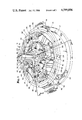
- FIG. 1 is a perspective view of an accelerometer in accordance with the present invention
- FIG. 2 is an exploded perspective view of apparatus for engaging an auxiliary mass in accordance with the invention
- FIG. 3 is a view of the accelerometer of FIG. 1 partially broken away to illustrate features thereof.
- FIG. 4 is a graph of the output of an accelerometer in accordance with the invention as a function of acceleration and proofmass center of gravity.
- FIG. 1 is a view, in perspective, of an accelerometer 10 in accordance with the invention.
- the accelerometer 10 includes a case 12 that is fixed to the accelerating body as distinguished from the inertial elements of the accelerometer, known generally as its "proofmass", that react during acceleration.
- the case 12 includes a planar upper surface 14 and fixtures 16 and 18 that provide points of attachment for conductors in electrical communication with input and output electronics, including servomechanisms, that measure and control the reactions of the proofmass along the orthogonal measuring axes of the instrument.
- a ring 20 forms a substantial portion of the proofmass of the accelerometer 10.
- Struts 22, 24, 26 and 28 that radiate generally therefrom define, in pairs, the orthogonal axes of the (two axis) accelerometer 10.
- Ring-like coil supports 30, 32, 34, and 36 underlie the ring 20 and radial struts 22, 24, 26 and 28 respectively. As will be seen in FIG. 3, the coil supports overlie servo-controlled torquer coils which provide corrective forces for restoring the proofmass to its null position during acceleration.
- Bucking magnets 38, 40, 42 and 44 are located at the centers of the coil supports.
- the bucking magnets comprise portions of four separate torquer magnet assemblies 46, 48, 50 and 52. Additional details of a typical assembly will be seen in the cross sectional view of FIG. 3. While the torquer coils, in conjunction with the torquer magnet assemblies, provide corrective forces for maintaining the null position of the proofmass, coils 54, 56, 58 and 60, in conjunction with additional sets of coils positioned within yokes 62, 64, 66 and 68 respectively, excite fields that allow the detection of displacements of pickoff coils (not shown) that are fixed to struts 22, 24, 26 and 28 respectively in response to sensed acceleration. As a result, error signals are produced during acceleration that are utilized by the instrument to drive servomechanisms which control the currents in the torquer coils.
- a substantially vertical structure is centered about the ring 20 of the proofmass.
- This structure only the upper half of which can be seen in FIG. 1, includes apparatus that allows the accelerometer to generate a plurality of proofmass torque measurements which are processed in accordance with the invention to produce acceleration data with reduced bias uncertainty.
- Three vertical piezoelectric strips 70, 72 and 74 can be seen to surround the vertical structure. (A fourth strip, opposite the strip 72, cannot be seen in the perspective view of FIG. 1.)
- the strips are joined at their upper ends, by means of epoxy or like fastening means, to side walls 76, 78, 80 and 82 respectively.
- Each side wall shown includes an interior wedge-like structure for retaining a spherical upper auxiliary mass 84 in one of two configurations.
- FIG. 2 Detail of the structures for retaining the auxiliary mass 84 (and a like spherical lower auxiliary mass not seen in FIG. 1) are shown in FIG. 2, an enlarged exploded perspective view thereof.
- the apparatus for retaining the spherical mass 84 comprises opposed pairs of side walls 76, 80 and 78, 82 respectively.
- the side walls are fixed to the ends of the vertical upper piezoelectric strips 70, 74 and 72, 85 (not shown in FIG. 1), respectively.
- Strips 72 and 85 are fixed to the accelerometer proofmass at the ring 20 while strips 70 and 74 are fixed to the case 12 by means of an arm 106, shown in FIGS. 1 and 3, that is connected to the upper portion of the suspension of the accelerometer.
- the inner surfaces of the side walls 76, 78, 80 and 82 include paired, planar protrusions (such as the protrusions 86 and 88 associated with side wall 76 having inclined opposed edges that act as retaining wedges. These retaining wedges are dimensioned to secure the auxiliary mass selectively to one of the two sets of opposed side walls in accordance with control voltages applied, in pairs, to opposed upper piezoelectric strips.
- Each piezoelectric strip comprises two sheets of piezoelectric material of opposed polarity. The sheets are bonded to a thin common beam of metal or the like.
- FIG. 3 is a view of the accelerometer 10 partially broken away to illustrate additional features thereof.
- a spherical lower auxiliary mass 94 is positioned near the bottom of the accelerometer.
- the lower mass is retained within a grasping arrangement that is functionally identical to that illustrated in FIG. 2 for retaining the upper mass 84.
- Side wall 95 including a wedge-like structure at its inner side as shown in FIG. 2, is secured to a lower case-fixed piezoelectric strip 96 while side wall 97 is secured to a lower proofmass-fixed piezoelectric strip 98. As shown in FIG.
- the case-fixed piezoelectric strips 74 and 96 are fixed, by means of epoxy, to structures that engage the upper end 104 of an accelerometer suspension 100 which, in turn, is rigidly engaged to the case-fixed arm 106.
- the proofmass-fixed piezoelectric strips 72 and 98 are similarly fixed to the inner edge of the ring 20.
- the proofmass of the accelerometer 10 comprises, in addition to the ring 20 and the four radial struts, the four pick-off coils, the four torquer coils, one pair of (upper or lower) piezoelectric strips and associated side walls, the lower portion of the suspension 100 and one of the (upper or lower) auxiliary masses.
- FIG. 4 is a graph which illustrates the operation and theoretical basis for measurement of acceleration or gravity in accordance with the present invention whereby the bias uncertainty inherent in such measurements is readily overcome.
- accelerometers are commonly employed to detect gravity. An accelerometer at rest may be tilted about an axis perpendicular to its sensitive axis and the component of the gravitational field thereby measured by the instrument.
- the notations CG1 and CG2 indicate the two distinct locations of the center of gravity of the proofmass of the accelerometer.
- the location of the center of gravity of the proofmass is a function in each instance of proofmass configuration.
- two separate configurations may be achieved in accordance with the described invention, the configuration differing by the identity of the auxiliary mass, upper or lower, which is associated with the proofmass in response to control voltages applied to the upper and lower sets of piezoelectric strips.
- Control voltages are applied to the upper and lower sets of piezoelectric strips in such a manner that the upper and lower auxiliary masses are alternately case-fixed and proofmass-fixed (i.e., grasped by opposed sets of piezoelectric strips which are fixed directly or indirectly to the case 12 or to the ring 20.)
- the spherical auxiliary masses need not be of equal size and/or distance from the center of suspension 100, the alternating positions of the center of gravity of the proofmass change the pendulosity of the accelerometer 10 and the polarity of the torque thereof.
- the switching of the center of gravity of the proofmass does not effect the current, i b , required to maintain the null position of the proofmass.
- T1 indicates the initiation of acceleration or tilt.
- the torquer current is increased at this time by the amount i a . This indicates that a current of i b +i a is now required to maintain the proofmass at null with its center of gravity in the GC1 position (this corresponds to the application of a set of voltages to the upper and lower sets of piezoelectric strips such that the upper auxiliary mass is proofmass-fixed while the lower auxiliary mass is case-fixed.)
- the center of gravity of the proofmass is switched to the CG2 position by a reversal of control voltages (upper auxiliary mass case-fixed, lower mass proofmass-fixed), causing the torquer current to be reduced to i b -i a .
- the change in torquer current from a value greater than i b to a value less than i b indicates a reversal in the polarity of the portion of the torque of the accelerometer that is attributable to an auxiliary mass.
- the aforementioned alternation of output torque values between i b +i a and i b -i a can be seen in FIG. 4 to continue as the upper and lower masses are alternately rendered proofmass-fixed and case-fixed.
- acceleration or gravity component By providing two measurements of torque as the body is accelerated or tilted, an accurate measurement of acceleration or gravity component, including a substantial reduction in uncertainty bias, can be obtained.
- This measure of acceleration or gravity component is equal to the difference between the torques produced by the two pendulosities of the proofmass during acceleration times an appropriate scale factor.
- the bias uncertainty, i b may be removed from the torque measurement.
- the above-stated result derives from the fact that the torquer current includes two distinct components, one of which is time-varying with accelerometer pendulosity, having an amplitude that is proportional to applied acceleration or gravity component and pendulosity.
- the other component of the output represents bias both at steady state and under transient conditions and is not modulated by pendulosity.
- a composite value representing a multiple of the portion of torquer current that is a function of pendulosity and acceleration or gravity component.
- the accelerometer suspension can be made more rugged than in the prior art, reducing the potential over-stressing or fatigue of the suspension from external vibrations that coincide with resonant frequencies.
Abstract
Description
Claims (15)
Priority Applications (1)
| Application Number | Priority Date | Filing Date | Title |
|---|---|---|---|
| US06/468,343 US4599896A (en) | 1983-02-22 | 1983-02-22 | High accuracy accelerometer |
Applications Claiming Priority (1)
| Application Number | Priority Date | Filing Date | Title |
|---|---|---|---|
| US06/468,343 US4599896A (en) | 1983-02-22 | 1983-02-22 | High accuracy accelerometer |
Publications (1)
| Publication Number | Publication Date |
|---|---|
| US4599896A true US4599896A (en) | 1986-07-15 |
Family
ID=23859434
Family Applications (1)
| Application Number | Title | Priority Date | Filing Date |
|---|---|---|---|
| US06/468,343 Expired - Lifetime US4599896A (en) | 1983-02-22 | 1983-02-22 | High accuracy accelerometer |
Country Status (1)
| Country | Link |
|---|---|
| US (1) | US4599896A (en) |
Cited By (15)
| Publication number | Priority date | Publication date | Assignee | Title |
|---|---|---|---|---|
| US4809545A (en) * | 1986-05-30 | 1989-03-07 | Mobil Oil Corporation | Gravimetry logging |
| FR2637689A1 (en) * | 1988-10-11 | 1990-04-13 | Deutsche Forsch Luft Raumfahrt | ACCELEROMETER |
| US4935883A (en) * | 1988-05-17 | 1990-06-19 | Sundstrand Data Control, Inc. | Apparatus and method for leveling a gravity measurement device |
| US4955108A (en) * | 1989-07-14 | 1990-09-11 | Litton Systems, Inc. | Protected hinge assembly for mechanical accelerometer |
| US5457993A (en) * | 1993-08-03 | 1995-10-17 | Sapuppo; Michele S. | Pendulous oscillating gyroscopic accelerometer |
| WO1997006441A1 (en) * | 1993-08-03 | 1997-02-20 | Sapuppo Michele S | Pendulous oscillating gyroscopic accelerometer |
| US5627314A (en) * | 1991-02-08 | 1997-05-06 | Alliedsignal, Inc. | Micromachined rate and acceleration sensor |
| US5905201A (en) * | 1997-10-28 | 1999-05-18 | Alliedsignal Inc. | Micromachined rate and acceleration sensor and method |
| WO2006096741A1 (en) * | 2005-03-07 | 2006-09-14 | Stewart Robert E | High accuracy strapdown digital accelerometer |
| US7257512B1 (en) | 2006-04-07 | 2007-08-14 | Honeywell International Inc. | Methods and systems for vibropendulous error compensation of acceleration sensors |
| EP1975631A2 (en) | 2007-03-28 | 2008-10-01 | Litton Systems, Inc. | Self-calibrating accelerometer |
| JP2009092583A (en) * | 2007-10-11 | 2009-04-30 | Nippon Signal Co Ltd:The | Drift suppression method of gyro sensor |
| EP2128565A1 (en) * | 2008-05-30 | 2009-12-02 | Northrop Grumman Guidance and Electronics Company, Inc. | Self-Calibrating Laser Semiconductor Accelerometer |
| ITUA20162172A1 (en) * | 2016-03-31 | 2017-10-01 | St Microelectronics Srl | ACCELEROMETRIC SENSOR MADE IN MEMS TECHNOLOGY WITH HIGH ACCURACY AND REDUCED SENSITIVITY TOWARDS TEMPERATURE AND AGING |
| US11002878B2 (en) * | 2016-10-21 | 2021-05-11 | The University Of Western Australia | Intrinsic gravity gradiometer and gravity gradiometry |
Citations (4)
| Publication number | Priority date | Publication date | Assignee | Title |
|---|---|---|---|---|
| US2132865A (en) * | 1934-10-05 | 1938-10-11 | Shell Dev | Gravitational instrument |
| US2559919A (en) * | 1947-04-03 | 1951-07-10 | Bolidens Gruv Ab | Apparatus for measuring forces, especially the force of gravity |
| US2842351A (en) * | 1955-08-11 | 1958-07-08 | Jerome A Rodder | Quartz fiber torsion ultramicrobalance |
| US3071008A (en) * | 1959-08-20 | 1963-01-01 | Litton Systems Inc | Acceleration measuring system |
-
1983
- 1983-02-22 US US06/468,343 patent/US4599896A/en not_active Expired - Lifetime
Patent Citations (4)
| Publication number | Priority date | Publication date | Assignee | Title |
|---|---|---|---|---|
| US2132865A (en) * | 1934-10-05 | 1938-10-11 | Shell Dev | Gravitational instrument |
| US2559919A (en) * | 1947-04-03 | 1951-07-10 | Bolidens Gruv Ab | Apparatus for measuring forces, especially the force of gravity |
| US2842351A (en) * | 1955-08-11 | 1958-07-08 | Jerome A Rodder | Quartz fiber torsion ultramicrobalance |
| US3071008A (en) * | 1959-08-20 | 1963-01-01 | Litton Systems Inc | Acceleration measuring system |
Cited By (27)
| Publication number | Priority date | Publication date | Assignee | Title |
|---|---|---|---|---|
| US4809545A (en) * | 1986-05-30 | 1989-03-07 | Mobil Oil Corporation | Gravimetry logging |
| US4935883A (en) * | 1988-05-17 | 1990-06-19 | Sundstrand Data Control, Inc. | Apparatus and method for leveling a gravity measurement device |
| FR2637689A1 (en) * | 1988-10-11 | 1990-04-13 | Deutsche Forsch Luft Raumfahrt | ACCELEROMETER |
| US5048339A (en) * | 1988-10-11 | 1991-09-17 | Deutsdche Forschungsanstalt Fur Luft- Und Raumfaht E.V. | Acceleration pick-up device |
| US4955108A (en) * | 1989-07-14 | 1990-09-11 | Litton Systems, Inc. | Protected hinge assembly for mechanical accelerometer |
| US5627314A (en) * | 1991-02-08 | 1997-05-06 | Alliedsignal, Inc. | Micromachined rate and acceleration sensor |
| US5920011A (en) * | 1991-02-08 | 1999-07-06 | Alliedsignal Inc. | Micromachined rate and acceleration sensor |
| US5457993A (en) * | 1993-08-03 | 1995-10-17 | Sapuppo; Michele S. | Pendulous oscillating gyroscopic accelerometer |
| WO1997006441A1 (en) * | 1993-08-03 | 1997-02-20 | Sapuppo Michele S | Pendulous oscillating gyroscopic accelerometer |
| EP0784797A1 (en) * | 1993-08-03 | 1997-07-23 | Michele S. Sapuppo | Pendulous oscillating gyroscopic accelerometer |
| EP0784797A4 (en) * | 1993-08-03 | 1997-12-17 | Michele S Sapuppo | Pendulous oscillating gyroscopic accelerometer |
| US5905201A (en) * | 1997-10-28 | 1999-05-18 | Alliedsignal Inc. | Micromachined rate and acceleration sensor and method |
| WO2006096741A1 (en) * | 2005-03-07 | 2006-09-14 | Stewart Robert E | High accuracy strapdown digital accelerometer |
| US7257512B1 (en) | 2006-04-07 | 2007-08-14 | Honeywell International Inc. | Methods and systems for vibropendulous error compensation of acceleration sensors |
| EP1975631A2 (en) | 2007-03-28 | 2008-10-01 | Litton Systems, Inc. | Self-calibrating accelerometer |
| JP2008241715A (en) * | 2007-03-28 | 2008-10-09 | Northrop Grumman Guidance & Electronics Co Inc | Self-calibrating accelerometer |
| EP1975631A3 (en) * | 2007-03-28 | 2012-02-08 | Litton Systems, Inc. | Self-calibrating accelerometer |
| JP2009092583A (en) * | 2007-10-11 | 2009-04-30 | Nippon Signal Co Ltd:The | Drift suppression method of gyro sensor |
| JP2009288247A (en) * | 2008-05-30 | 2009-12-10 | Northrop Grumman Guidance & Electronics Co Inc | Self-calibrating laser semiconductor accelerometer |
| US20090293583A1 (en) * | 2008-05-30 | 2009-12-03 | Northrop Grumman Guidance And Electronics Company, Inc. | Self-calibrating laser semiconductor accelerometer |
| US7980115B2 (en) | 2008-05-30 | 2011-07-19 | Northrop Grumman Guidance and Electronic Co, Inc. | Self-calibrating laser semiconductor accelerometer |
| EP2128565A1 (en) * | 2008-05-30 | 2009-12-02 | Northrop Grumman Guidance and Electronics Company, Inc. | Self-Calibrating Laser Semiconductor Accelerometer |
| ITUA20162172A1 (en) * | 2016-03-31 | 2017-10-01 | St Microelectronics Srl | ACCELEROMETRIC SENSOR MADE IN MEMS TECHNOLOGY WITH HIGH ACCURACY AND REDUCED SENSITIVITY TOWARDS TEMPERATURE AND AGING |
| EP3226008A1 (en) * | 2016-03-31 | 2017-10-04 | STMicroelectronics S.r.l. | Accelerometric sensor in mems technology having high accuracy and low sensitivity to temperature and ageing |
| US10591505B2 (en) | 2016-03-31 | 2020-03-17 | Stmicroelectronics S.R.L. | Accelerometric sensor in MEMS technology having high accuracy and low sensitivity to temperature and ageing |
| US11408904B2 (en) | 2016-03-31 | 2022-08-09 | Stmicroelectronics S.R.L. | Accelerometric sensor in mems technology having high accuracy and low sensitivity to temperature and ageing |
| US11002878B2 (en) * | 2016-10-21 | 2021-05-11 | The University Of Western Australia | Intrinsic gravity gradiometer and gravity gradiometry |
Similar Documents
| Publication | Publication Date | Title |
|---|---|---|
| US4599896A (en) | High accuracy accelerometer | |
| US6701786B2 (en) | Closed loop analog gyro rate sensor | |
| US4750364A (en) | Angular velocity and acceleration sensor | |
| US7549334B2 (en) | Small angle bias measurement mechanism for MEMS instruments | |
| US4611491A (en) | Accelerometer system | |
| US8397568B2 (en) | Bias measurement for MEMS gyroscopes and accelerometers | |
| EP0243468B1 (en) | Signal processor for inertial measurement using coriolis force sensing accelerometer arrangements | |
| US5987986A (en) | Navigation grade micromachined rotation sensor system | |
| US6826960B2 (en) | Triaxial acceleration sensor | |
| US5712426A (en) | Pendulous oscillating gyroscopic and accelerometer multisensor and amplitude oscillating gyroscope | |
| US20100024548A1 (en) | Scale Factor Measurement For Mems Gyroscopes And Accelerometers | |
| Savage | Strapdown sensors | |
| US3486383A (en) | Vibrating beam transducer | |
| US8079259B2 (en) | MEMS gyroscope with output oscillation about the normal to the plane | |
| US3413859A (en) | Digital rate gyro | |
| EP0405152B1 (en) | Method for adjusting a spinning piezoelectric beam of a dual-axis angular rate sensor | |
| CA1117786A (en) | Angular accelerometer stabilized pendulum | |
| US3974701A (en) | Spin coupled, angular rate sensitive inertial sensors with optional acceleration sensing capability and method of fabricating same | |
| US3318160A (en) | Vibra-rotor gyroscope | |
| US4462254A (en) | Sensor assembly having means for cancellation of harmonic induced bias from a two-axis linear accelerometer | |
| KR100203315B1 (en) | Two axis navigation grade micromachined rotation sensor system | |
| US4068533A (en) | ESG Reflected impedance pickoff | |
| CA1296543C (en) | Translational accelerometer and accelerometer assembly method | |
| US5488865A (en) | Wide-band servo accelerometer with flat leaf flexure suspension | |
| US5092173A (en) | Secondary accelerometer pickoff |
Legal Events
| Date | Code | Title | Description |
|---|---|---|---|
| AS | Assignment |
Owner name: LITTON INDUSTRIES, INC.; 360 NORTH CRESCENT DR., B Free format text: ASSIGNMENT OF ASSIGNORS INTEREST.;ASSIGNOR:STEWART, ROBERT E.;REEL/FRAME:004099/0732 Effective date: 19830209 |
|
| FEPP | Fee payment procedure |
Free format text: PAYOR NUMBER ASSIGNED (ORIGINAL EVENT CODE: ASPN); ENTITY STATUS OF PATENT OWNER: LARGE ENTITY |
|
| AS | Assignment |
Owner name: LITTON SYSTEMS, INC., 360 NORTH CRESCENT DRIVE, BE Free format text: ASSIGNMENT OF ASSIGNORS INTEREST.;ASSIGNOR:LITTON INDUSTRIES, INC.,;REEL/FRAME:004523/0048 Effective date: 19860221 |
|
| STCF | Information on status: patent grant |
Free format text: PATENTED CASE |
|
| FPAY | Fee payment |
Year of fee payment: 4 |
|
| FPAY | Fee payment |
Year of fee payment: 8 |
|
| FPAY | Fee payment |
Year of fee payment: 12 |