US4602240A - Apparatus for and method of attenuating power line carrier communication signals passing between substation distribution lines and transmission lines through substation transformers - Google Patents
Apparatus for and method of attenuating power line carrier communication signals passing between substation distribution lines and transmission lines through substation transformers Download PDFInfo
- Publication number
- US4602240A US4602240A US06/592,139 US59213984A US4602240A US 4602240 A US4602240 A US 4602240A US 59213984 A US59213984 A US 59213984A US 4602240 A US4602240 A US 4602240A
- Authority
- US
- United States
- Prior art keywords
- substation
- shunt
- phase
- transmission line
- network
- Prior art date
- Legal status (The legal status is an assumption and is not a legal conclusion. Google has not performed a legal analysis and makes no representation as to the accuracy of the status listed.)
- Expired - Fee Related
Links
Images

Classifications
-
- H—ELECTRICITY
- H04—ELECTRIC COMMUNICATION TECHNIQUE
- H04B—TRANSMISSION
- H04B3/00—Line transmission systems
- H04B3/54—Systems for transmission via power distribution lines
- H04B3/56—Circuits for coupling, blocking, or by-passing of signals
-
- H—ELECTRICITY
- H04—ELECTRIC COMMUNICATION TECHNIQUE
- H04B—TRANSMISSION
- H04B2203/00—Indexing scheme relating to line transmission systems
- H04B2203/54—Aspects of powerline communications not already covered by H04B3/54 and its subgroups
- H04B2203/5404—Methods of transmitting or receiving signals via power distribution lines
- H04B2203/5425—Methods of transmitting or receiving signals via power distribution lines improving S/N by matching impedance, noise reduction, gain control
-
- H—ELECTRICITY
- H04—ELECTRIC COMMUNICATION TECHNIQUE
- H04B—TRANSMISSION
- H04B2203/00—Indexing scheme relating to line transmission systems
- H04B2203/54—Aspects of powerline communications not already covered by H04B3/54 and its subgroups
- H04B2203/5462—Systems for power line communications
- H04B2203/5466—Systems for power line communications using three phases conductors
-
- H—ELECTRICITY
- H04—ELECTRIC COMMUNICATION TECHNIQUE
- H04B—TRANSMISSION
- H04B2203/00—Indexing scheme relating to line transmission systems
- H04B2203/54—Aspects of powerline communications not already covered by H04B3/54 and its subgroups
- H04B2203/5462—Systems for power line communications
- H04B2203/5483—Systems for power line communications using coupling circuits
-
- H—ELECTRICITY
- H04—ELECTRIC COMMUNICATION TECHNIQUE
- H04B—TRANSMISSION
- H04B2203/00—Indexing scheme relating to line transmission systems
- H04B2203/54—Aspects of powerline communications not already covered by H04B3/54 and its subgroups
- H04B2203/5462—Systems for power line communications
- H04B2203/5491—Systems for power line communications using filtering and bypassing
Definitions
- the present invention is generally related to electrical signals and more specifically related to communication frequency signals superimposed on electric power distribution lines. Even more specifically the invention is related to attenuating crosstalk between substation distribution networks of zero-sequence power line carrier communication signals intended solely for use on a specific substation electrical power distribution network.
- control and monitoring operations e.g., operating relays and reading electrical power usage meters
- PLC power line carrier
- bandpass attenuation circuits are normally more complicated and thus more expensive and less reliable than either high pass or low pass attenuation circuits.
- the present invention attempts to control distribution communications crosstalk between substations by preventing the PLC frequency signals from ever getting to the main transmission line in the first place. This is accomplished by placing a capacitor bank intermediate the substation transformer and any communication equipment on that substation network where the capacitor bank is essentially a shunt to communication frequency signals and yet has a relatively high impedance to the 50 or 60 Hz power frequency. As mentioned supra, if the conditions of no unbalanced feeder phase loading exists, the zero-sequence PLC communication signals will never be transmitted through the substation transformer to the main transmission line.
- a further factor for attenuating the PLC frequency signals to or from the transmission line involves connecting an inductance between the common wye-point of the capacitor bank and line neutral to form the shunt element of an L-type attenuation circuit where the series impedance of the substation transformer and the series impedance of the transmission line forms the series element of the L-configured attenuation network. If another substation has a capacitor bank and inductive element configured as just mentioned, this will constitute the other shunt element of a pi attenuator network. However, in both cases the shunt attenuator element of the attenuator network is physically located on the substation distribution network and thus will not in any way interfere with the higher frequency communication signals that may be used only on the main transmission line. This approach eliminates the design problems of cost and reliability inherent in prior art approaches to trapping PLC signals at transmission voltage levels.
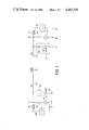
- FIG. 1 is a simplified single-line schematic (idealized) of the attenuator network either for the L configuration or the pi configuration;
- FIG. 2 is a schematic diagram representative of a segment of transmission line and having two illustrated substation distribution networks each having a shunt attenuator element.
- a main high voltage transmission line is represented by an inductance 10 which is connected to a substation transformer equivalent series inductance 12.
- the other end of inductance 12 is connected to a common junction point 14 which is connected through an inductance 16 and a signal generator 18 to neutral or ground 20.
- Junction point 14, representing the associated substation distribution operating bus is also connected through a capacitive element shown within a dash line block 22.
- the capacitive element within block 22 is connected through a shunt inductive impedance 24 to ground or neutral 20.
- Junction point 14 is also connected through an inductance 26 representing the series impedance of the three-phase substation distribution network to one or more transceivers or other communication receiving devices 28 which communication device is also connected to ground 20.
- junction point 32 representing the associated substation distribution operating bus, is connected through a shunt impedance element in dash line block 34 to show that this block is optional.
- the block contains a capacitive element 36 and an inductive element 38.
- junction point 32 is also connected through a series equivalent impedance 40 and a signal generator or communication device 42 to ground or neutral 20.
- junction point 32 is connected through a further series inductance 44 representative of the distribution lines and transformers for the righthand substation network and through a transceiver or other communication receiving device 46 to ground 20.
- a three-phase transmission line segment generally indicated as 50 contains the three conductors 52, 54 and 56.
- This transmission line segment is represented generally by the inductance 10 in FIG. 1.
- a three-phase substation transformer generally designated as 58 having a primary winding 60 and a secondary winding 62.
- the primary winding is connected in a delta configuration while secondary winding 62 is connected in a grounded-wye type configuration.
- the common point of the wye (wye-point) is connected to ground 64.
- the three-phase lines connected to secondary winding 62 are labeled with designators 66, 68 and 70. These three lines are shown to have optional voltage regulators designated as 72, 74 and 76 respectively.
- a capacitor bank generally designated as 78 is connected in a wye configuration between the signal coupling bank 88 and the substation transformer 58.
- the capacitor bank 78 is connected between the voltage regulators and the substation transformer 58.
- a capacitor bank of smallest logistically convenient size is recommended.
- Such a capacitor bank equalizes the signal voltage among the phases by nearly shorting them together at carrier frequency, due to the very low reactance of the capacitors at carrier frequency.
- This forcing function causes the signal voltage on each power phase conductor to have very nearly the same amplitude and phase with respect to neutral, thus corresponding closely to the definition of a zero-sequence signal.
- the capacitor bank must be connected immediately to the substation transformer with any independent single-phase regulators farther downstream.
- the signal coupling bank is typically connected through standard disconnect and protection means, to the distribution operating bus in the substation. It is of little consequence whether such regulators appear upstream of the signal coupling bank, as when regulating the entire substation operating bus, or downstream of the signal coupling bank, as when regulating (a) particular feeder(s) served by the operating bus.
- regulators When regulators are incorporated within the substation transformer, they are invariably three-phase coordinated (ganged together) under common control of a single tap changer mechanism. Thus, tap ratios are changed simultaneously and equally per phase and do not upset the equalizing effect of the capacitor bank.
- This capacitor bank has individual capacitors 80, 82 and 84.
- the common wye-point in the capacitor bank is connected to an inductor or inductive element 86 which has its other end connected to neutral or ground 64.
- a signal coupling three-phase transformer bank 88 and associated signal generator 89 is shown connected on the downstream side of the capacitor bank (and optional voltage regulators 72 through 76) and provides a means of supplying zero-sequence carrier communication signals to the three-phase substation distribution network on the left side of FIG. 2.
- This transformer 88 and signal generator 89 combination is represented respectively by the inductance 16 and the signal means 18 in FIG. 1.
- the capacitor bank 78 and the inductor 86 are represented by elements 22 and 24 in FIG. 1.
- FIG. 1 is representative of the series inductance of the substation transformer 58 in FIG. 2.
- a further substation transformer 90 having a delta-connected primary winding 92 and a wye-connected secondary 94.
- the center or common wye-point of secondary winding 94 is connected to ground 96.
- the isolation afforded by transformers 58 and 90 remove concern for whether grounds 64 and 96 are at the same potential.
- both ground 64 and 96 in FIG. 2 are representatively the same as common ground 20 in FIG. 1.
- the output leads of secondary 94 are connected to network distribution lines designated as 98, 100 and 102.
- a capacitor bank generally designated as 104 has individual capacitors 106, 108 and 110.
- the common wye-point of capacitor bank 104 is connected through an inductance 112 to ground 96.
- a set of voltage regulators generally designated as 114 are optionally connected in a manner previously discussed on the lefthand side of FIG. 2 to each of the lines 98, 100 and 102.
- a signal coupling transformer generally designated as 116 receiving signal current from a carrier communication source 118 and within transformer 116 undergoing mode transformation from a simple single phase current to three equal zero-sequence-type substation distribution power line carrier communication signal currents which under balanced conditions will be exactly the same amplitude and phase in each of lines 98, 100, and 102.
- signal current transforms equally (but not necessarily signal voltage). Signal line currents and voltages are equal only if balanced conditions exist throughout. Signal currents in coupling bank windings are always equal irrespective of balance.
- the element 118 in conjunction with transformer 116 is represented respectively by the elements 42 and 40 in FIG. 1.
- Further communication devices of either the receive-only nature, such as relays, or of the transceiver nature, such as meter reading and reporting devices, are not shown on either side of FIG. 2 but are represented by elements 28 and 46 as shown in FIG. 1.
- the present invention through the use of the capacitor bank such as 78 physically located near the substation transformer 58 and upstream from any communications equipment, not only causes an attenuation of unbalanced components of the signal in the capacitor bank itself but in addition, significantly reduces the unbalance of the amplitude of the three power line communication carrier signals as applied per phase to the primary 62 of transformer 58 to likewise reduce the amplitude of any signals passing through transformer 58 but in addition, through the use of shunt inductor element 86, passes a considerable portion of these signals to neutral 64.
- the capacitor bank 78 provides a considerable attenuation of unbalanced signals by itself and in combination with inductor element 86 provides even further attenuation.
- this network provides a like attenuation of noise and undesired signals arriving at the substation from its own distribution network that would typically interfere with the communication frequency signals such that the amplitude of the signal generator can be increased somewhat along with increasing the sensitivity of any substation receivers to compensate for any reduction in signal amplitude caused by the attenuation network combination of 78 and 86.
- the capacitor bank significantly reduces unbalanced signals arriving at the substation from the transmission line and an L-type attenuation network is presented to any communication signals arriving at the substation from the transmission line, to further reduce the likelihood of any interfering communication signals therefrom appearing on the distribution network.
- a similar shunt element is used at a remote substation distribution network, that is experiencing particular crosstalk problems due to standing wave conditions, such as shown in either the righthand side of FIG. 2 or by the dash line block 34 in FIG.
- this further shunt element combines with the previous mentioned series and shunt elements of FIG. 1 to form a pi-type attenuation network.
- the signals from the lefthand portion of FIG. 1 not only are attenuated in being transmitted to the transmission line but are even further attenuated, after passing through the substation transformer represented by series inductance 30, by the shunt element 34 so that the signals are a very minimal amplitude by the time they reach the remote substation distribution network and the communication devices represented by elements 42 and 46 in FIG. 1.
Abstract
Description
Claims (9)
Priority Applications (1)
| Application Number | Priority Date | Filing Date | Title |
|---|---|---|---|
| US06/592,139 US4602240A (en) | 1984-03-22 | 1984-03-22 | Apparatus for and method of attenuating power line carrier communication signals passing between substation distribution lines and transmission lines through substation transformers |
Applications Claiming Priority (1)
| Application Number | Priority Date | Filing Date | Title |
|---|---|---|---|
| US06/592,139 US4602240A (en) | 1984-03-22 | 1984-03-22 | Apparatus for and method of attenuating power line carrier communication signals passing between substation distribution lines and transmission lines through substation transformers |
Publications (1)
| Publication Number | Publication Date |
|---|---|
| US4602240A true US4602240A (en) | 1986-07-22 |
Family
ID=24369465
Family Applications (1)
| Application Number | Title | Priority Date | Filing Date |
|---|---|---|---|
| US06/592,139 Expired - Fee Related US4602240A (en) | 1984-03-22 | 1984-03-22 | Apparatus for and method of attenuating power line carrier communication signals passing between substation distribution lines and transmission lines through substation transformers |
Country Status (1)
| Country | Link |
|---|---|
| US (1) | US4602240A (en) |
Cited By (33)
| Publication number | Priority date | Publication date | Assignee | Title |
|---|---|---|---|---|
| US4766414A (en) * | 1986-06-17 | 1988-08-23 | Westinghouse Electric Corp. | Power line communication interference preventing circuit |
| US5818821A (en) * | 1994-12-30 | 1998-10-06 | Intelogis, Inc. | Universal lan power line carrier repeater system and method |
| EP0877494A2 (en) * | 1997-05-08 | 1998-11-11 | AT&T Corp. | Active ground compensation for power line communication |
| US5930099A (en) * | 1998-06-30 | 1999-07-27 | Siemens Westinghouse Power Corporation | Grounding arrangement for a powerline system |
| US6037678A (en) * | 1997-10-03 | 2000-03-14 | Northern Telecom Limited | Coupling communications signals to a power line |
| US6317031B1 (en) * | 1996-08-06 | 2001-11-13 | Nortel Networks Limited | Power line communications |
| US6377163B1 (en) * | 2000-09-21 | 2002-04-23 | Home Touch Lighting Systems Llc | Power line communication circuit |
| US6452482B1 (en) | 1999-12-30 | 2002-09-17 | Ambient Corporation | Inductive coupling of a data signal to a power transmission cable |
| US6545453B2 (en) | 2001-04-03 | 2003-04-08 | Abb Inc. | Systems and methods for providing voltage regulation externally to a power transformer |
| US6809633B2 (en) | 2001-03-29 | 2004-10-26 | Ambient Corporation | Coupling broadband modems to power lines |
| US20040227623A1 (en) * | 2003-05-07 | 2004-11-18 | Telkonet, Inc. | Network topology and packet routing method using low voltage power wiring |
| US20040233928A1 (en) * | 2003-05-07 | 2004-11-25 | Telkonet, Inc. | Network topology and packet routing method using low voltage power wiring |
| US20050046550A1 (en) * | 2001-10-02 | 2005-03-03 | Crenshaw Ralph E. | Method and apparatus for attaching power line communications to customer premises |
| US20050062589A1 (en) * | 1999-12-30 | 2005-03-24 | Ambient Corporation | Arrangement of inductive couplers for data communication |
| US20050253690A1 (en) * | 2001-10-02 | 2005-11-17 | Telkonet Communications, Inc. | Method and apparatus for attaching power line communications to customer premises |
| US20060087382A1 (en) * | 2004-10-25 | 2006-04-27 | Ambient Corporation | Inductive coupler for power line communications |
| US7069091B2 (en) | 2001-11-01 | 2006-06-27 | Salton, Inc. | Intelligent microwave oven appliance |
| US7091849B1 (en) * | 2004-05-06 | 2006-08-15 | At&T Corp. | Inbound interference reduction in a broadband powerline system |
| US20060193310A1 (en) * | 2005-02-25 | 2006-08-31 | Telkonet, Inc. | Local area network above telephony methods and devices |
| US20060193313A1 (en) * | 2005-02-25 | 2006-08-31 | Telkonet, Inc. | Local area network above telephony infrastructure |
| US20060193336A1 (en) * | 2005-02-25 | 2006-08-31 | Telkonet, Inc. | Local area network above cable television methods and devices |
| US7151968B2 (en) | 2001-11-01 | 2006-12-19 | Salton, Inc. | Intelligent coffeemaker appliance |
| US20080117091A1 (en) * | 2004-11-08 | 2008-05-22 | Serconet Ltd. | Outlet with analog signal adapter, a method for use thereof and a network using said outlet |
| USRE40492E1 (en) | 2000-02-10 | 2008-09-09 | Telkonet Communications, Inc. | Power line telephony exchange |
| US7715534B2 (en) | 2000-03-20 | 2010-05-11 | Mosaid Technologies Incorporated | Telephone outlet for implementing a local area network over telephone lines and a local area network using such outlets |
| US7852874B2 (en) | 1998-07-28 | 2010-12-14 | Mosaid Technologies Incorporated | Local area network of serial intelligent cells |
| US7876767B2 (en) | 2000-04-19 | 2011-01-25 | Mosaid Technologies Incorporated | Network combining wired and non-wired segments |
| US7881462B2 (en) | 2004-02-16 | 2011-02-01 | Mosaid Technologies Incorporated | Outlet add-on module |
| US7990908B2 (en) | 2002-11-13 | 2011-08-02 | Mosaid Technologies Incorporated | Addressable outlet, and a network using the same |
| US20120274303A1 (en) * | 2010-01-25 | 2012-11-01 | Wataru Yamamori | Substation automatic control system |
| US20150268290A1 (en) * | 2012-10-24 | 2015-09-24 | State Grid Corporation Of China (Sgcc) | Method for On-Line Diagnosing Gradually-Changing Fault of Electronic Current Transformers |
| RU2638574C1 (en) * | 2016-06-20 | 2017-12-14 | Акционерное общество "Проектно-изыскательский и научно-исследовательский институт по проектированию энергетических систем и электрических сетей "ЭНЕРГОСЕТЬПРОЕКТ" (АО "Институт "ЭНЕРГОСЕТЬПРОЕКТ") | Medium voltage substation |
| RU2643350C1 (en) * | 2016-10-17 | 2018-02-01 | Акционерное общество "Проектно-изыскательский и научно-исследовательский институт по проектированию энергетических систем и электрических сетей "ЭНЕРГОСЕТЬПРОЕКТ" (АО "Институт "ЭНЕРГОСЕТЬПРОЕКТ") | Distribution device in ac network |
Citations (3)
| Publication number | Priority date | Publication date | Assignee | Title |
|---|---|---|---|---|
| US4433284A (en) * | 1982-04-07 | 1984-02-21 | Rockwell International Corporation | Power line communications bypass around delta-wye transformer |
| US4458236A (en) * | 1982-04-13 | 1984-07-03 | Rockwell International Corporation | Communications signal coupling around wye/delta power transformation |
| US4473816A (en) * | 1982-04-13 | 1984-09-25 | Rockwell International Corporation | Communications signal bypass around power line transformer |
-
1984
- 1984-03-22 US US06/592,139 patent/US4602240A/en not_active Expired - Fee Related
Patent Citations (3)
| Publication number | Priority date | Publication date | Assignee | Title |
|---|---|---|---|---|
| US4433284A (en) * | 1982-04-07 | 1984-02-21 | Rockwell International Corporation | Power line communications bypass around delta-wye transformer |
| US4458236A (en) * | 1982-04-13 | 1984-07-03 | Rockwell International Corporation | Communications signal coupling around wye/delta power transformation |
| US4473816A (en) * | 1982-04-13 | 1984-09-25 | Rockwell International Corporation | Communications signal bypass around power line transformer |
Cited By (62)
| Publication number | Priority date | Publication date | Assignee | Title |
|---|---|---|---|---|
| US4766414A (en) * | 1986-06-17 | 1988-08-23 | Westinghouse Electric Corp. | Power line communication interference preventing circuit |
| US5818821A (en) * | 1994-12-30 | 1998-10-06 | Intelogis, Inc. | Universal lan power line carrier repeater system and method |
| US6317031B1 (en) * | 1996-08-06 | 2001-11-13 | Nortel Networks Limited | Power line communications |
| EP0877494A2 (en) * | 1997-05-08 | 1998-11-11 | AT&T Corp. | Active ground compensation for power line communication |
| EP0877494A3 (en) * | 1997-05-08 | 1999-09-08 | AT&T Corp. | Active ground compensation for power line communication |
| US6037678A (en) * | 1997-10-03 | 2000-03-14 | Northern Telecom Limited | Coupling communications signals to a power line |
| US5930099A (en) * | 1998-06-30 | 1999-07-27 | Siemens Westinghouse Power Corporation | Grounding arrangement for a powerline system |
| US7852874B2 (en) | 1998-07-28 | 2010-12-14 | Mosaid Technologies Incorporated | Local area network of serial intelligent cells |
| US7978726B2 (en) | 1998-07-28 | 2011-07-12 | Mosaid Technologies Incorporated | Local area network of serial intelligent cells |
| US8908673B2 (en) | 1998-07-28 | 2014-12-09 | Conversant Intellectual Property Management Incorporated | Local area network of serial intelligent cells |
| US8885660B2 (en) | 1998-07-28 | 2014-11-11 | Conversant Intellectual Property Management Incorporated | Local area network of serial intelligent cells |
| US8885659B2 (en) | 1998-07-28 | 2014-11-11 | Conversant Intellectual Property Management Incorporated | Local area network of serial intelligent cells |
| US8867523B2 (en) | 1998-07-28 | 2014-10-21 | Conversant Intellectual Property Management Incorporated | Local area network of serial intelligent cells |
| US20030160684A1 (en) * | 1999-12-30 | 2003-08-28 | Ambient Corporation | Inductive coupling of a data signal for a power transmission cable |
| US6646447B2 (en) | 1999-12-30 | 2003-11-11 | Ambient Corporation | Identifying one of a plurality of wires of a power transmission cable |
| US20050062589A1 (en) * | 1999-12-30 | 2005-03-24 | Ambient Corporation | Arrangement of inductive couplers for data communication |
| US6897764B2 (en) | 1999-12-30 | 2005-05-24 | Ambient Corporation | Inductive coupling of a data signal for a power transmission cable |
| US7154382B2 (en) | 1999-12-30 | 2006-12-26 | Ambient Corporation | Arrangement of inductive couplers for data communication |
| US6452482B1 (en) | 1999-12-30 | 2002-09-17 | Ambient Corporation | Inductive coupling of a data signal to a power transmission cable |
| USRE40492E1 (en) | 2000-02-10 | 2008-09-09 | Telkonet Communications, Inc. | Power line telephony exchange |
| US7715534B2 (en) | 2000-03-20 | 2010-05-11 | Mosaid Technologies Incorporated | Telephone outlet for implementing a local area network over telephone lines and a local area network using such outlets |
| US8363797B2 (en) | 2000-03-20 | 2013-01-29 | Mosaid Technologies Incorporated | Telephone outlet for implementing a local area network over telephone lines and a local area network using such outlets |
| US8855277B2 (en) | 2000-03-20 | 2014-10-07 | Conversant Intellectual Property Managment Incorporated | Telephone outlet for implementing a local area network over telephone lines and a local area network using such outlets |
| US8867506B2 (en) | 2000-04-19 | 2014-10-21 | Conversant Intellectual Property Management Incorporated | Network combining wired and non-wired segments |
| US8982903B2 (en) | 2000-04-19 | 2015-03-17 | Conversant Intellectual Property Management Inc. | Network combining wired and non-wired segments |
| US8848725B2 (en) | 2000-04-19 | 2014-09-30 | Conversant Intellectual Property Management Incorporated | Network combining wired and non-wired segments |
| US8873575B2 (en) | 2000-04-19 | 2014-10-28 | Conversant Intellectual Property Management Incorporated | Network combining wired and non-wired segments |
| US7876767B2 (en) | 2000-04-19 | 2011-01-25 | Mosaid Technologies Incorporated | Network combining wired and non-wired segments |
| US8982904B2 (en) | 2000-04-19 | 2015-03-17 | Conversant Intellectual Property Management Inc. | Network combining wired and non-wired segments |
| US8873586B2 (en) | 2000-04-19 | 2014-10-28 | Conversant Intellectual Property Management Incorporated | Network combining wired and non-wired segments |
| WO2003028227A1 (en) * | 2000-09-21 | 2003-04-03 | Home Touch Lighting Systems, Llc | Power line communication circuit |
| US6377163B1 (en) * | 2000-09-21 | 2002-04-23 | Home Touch Lighting Systems Llc | Power line communication circuit |
| US6809633B2 (en) | 2001-03-29 | 2004-10-26 | Ambient Corporation | Coupling broadband modems to power lines |
| US6545453B2 (en) | 2001-04-03 | 2003-04-08 | Abb Inc. | Systems and methods for providing voltage regulation externally to a power transformer |
| US20050253690A1 (en) * | 2001-10-02 | 2005-11-17 | Telkonet Communications, Inc. | Method and apparatus for attaching power line communications to customer premises |
| US20050046550A1 (en) * | 2001-10-02 | 2005-03-03 | Crenshaw Ralph E. | Method and apparatus for attaching power line communications to customer premises |
| US7091831B2 (en) * | 2001-10-02 | 2006-08-15 | Telkonet Communications, Inc. | Method and apparatus for attaching power line communications to customer premises |
| US7151968B2 (en) | 2001-11-01 | 2006-12-19 | Salton, Inc. | Intelligent coffeemaker appliance |
| US7069091B2 (en) | 2001-11-01 | 2006-06-27 | Salton, Inc. | Intelligent microwave oven appliance |
| US7990908B2 (en) | 2002-11-13 | 2011-08-02 | Mosaid Technologies Incorporated | Addressable outlet, and a network using the same |
| US20040227623A1 (en) * | 2003-05-07 | 2004-11-18 | Telkonet, Inc. | Network topology and packet routing method using low voltage power wiring |
| US20040233928A1 (en) * | 2003-05-07 | 2004-11-25 | Telkonet, Inc. | Network topology and packet routing method using low voltage power wiring |
| US7881462B2 (en) | 2004-02-16 | 2011-02-01 | Mosaid Technologies Incorporated | Outlet add-on module |
| US9577706B2 (en) | 2004-05-06 | 2017-02-21 | At&T Intellectual Property Ii, L.P. | Outbound interference reduction in a broadband powerline system |
| US9887734B2 (en) | 2004-05-06 | 2018-02-06 | At&T Intellectual Property Ii, L.P. | Outbound interference reduction in a broadband powerline system |
| US7453353B1 (en) | 2004-05-06 | 2008-11-18 | At&T Intellectual Property Ii, L.P. | Inbound interference reduction in a broadband powerline system |
| US10700737B2 (en) | 2004-05-06 | 2020-06-30 | At&T Intellectual Property Ii, L.P. | Outbound interference reduction in a broadband powerline system |
| US10312965B2 (en) | 2004-05-06 | 2019-06-04 | At&T Intellectual Property Ii, L.P. | Outbound interference reduction in a broadband powerline system |
| US7091849B1 (en) * | 2004-05-06 | 2006-08-15 | At&T Corp. | Inbound interference reduction in a broadband powerline system |
| US8938021B1 (en) | 2004-05-06 | 2015-01-20 | Paul Shala Henry | Outbound interference reduction in a broadband powerline system |
| US7170367B2 (en) | 2004-10-25 | 2007-01-30 | Ambient Corporation | Inductive coupler for power line communications |
| US20060087382A1 (en) * | 2004-10-25 | 2006-04-27 | Ambient Corporation | Inductive coupler for power line communications |
| US20080117091A1 (en) * | 2004-11-08 | 2008-05-22 | Serconet Ltd. | Outlet with analog signal adapter, a method for use thereof and a network using said outlet |
| US7873058B2 (en) | 2004-11-08 | 2011-01-18 | Mosaid Technologies Incorporated | Outlet with analog signal adapter, a method for use thereof and a network using said outlet |
| US20060193336A1 (en) * | 2005-02-25 | 2006-08-31 | Telkonet, Inc. | Local area network above cable television methods and devices |
| US20060193310A1 (en) * | 2005-02-25 | 2006-08-31 | Telkonet, Inc. | Local area network above telephony methods and devices |
| US20060193313A1 (en) * | 2005-02-25 | 2006-08-31 | Telkonet, Inc. | Local area network above telephony infrastructure |
| US20120274303A1 (en) * | 2010-01-25 | 2012-11-01 | Wataru Yamamori | Substation automatic control system |
| US8494684B2 (en) * | 2010-01-25 | 2013-07-23 | Kabushiki Kaisha Toshiba | Substation automatic control system |
| US20150268290A1 (en) * | 2012-10-24 | 2015-09-24 | State Grid Corporation Of China (Sgcc) | Method for On-Line Diagnosing Gradually-Changing Fault of Electronic Current Transformers |
| RU2638574C1 (en) * | 2016-06-20 | 2017-12-14 | Акционерное общество "Проектно-изыскательский и научно-исследовательский институт по проектированию энергетических систем и электрических сетей "ЭНЕРГОСЕТЬПРОЕКТ" (АО "Институт "ЭНЕРГОСЕТЬПРОЕКТ") | Medium voltage substation |
| RU2643350C1 (en) * | 2016-10-17 | 2018-02-01 | Акционерное общество "Проектно-изыскательский и научно-исследовательский институт по проектированию энергетических систем и электрических сетей "ЭНЕРГОСЕТЬПРОЕКТ" (АО "Институт "ЭНЕРГОСЕТЬПРОЕКТ") | Distribution device in ac network |
Similar Documents
| Publication | Publication Date | Title |
|---|---|---|
| US4602240A (en) | Apparatus for and method of attenuating power line carrier communication signals passing between substation distribution lines and transmission lines through substation transformers | |
| US4473816A (en) | Communications signal bypass around power line transformer | |
| US4890089A (en) | Distribution of line carrier communications | |
| US4433284A (en) | Power line communications bypass around delta-wye transformer | |
| US4142178A (en) | High voltage signal coupler for a distribution network power line carrier communication system | |
| US4357598A (en) | Three-phase power distribution network communication system | |
| US4012733A (en) | Distribution power line communication system including a messenger wire communications link | |
| US4300126A (en) | Method and apparatus, for power line communications using zero crossing load interruption | |
| US2488400A (en) | Toroidal coil-terminal bushing coupling power line and telephone circuit | |
| US4254402A (en) | Transformer arrangement for coupling a communication signal to a three-phase power line | |
| US4481501A (en) | Transformer arrangement for coupling a communication signal to a three-phase power line | |
| EP1050975B1 (en) | Communications apparatus for use with an electricity network | |
| US4065763A (en) | Distribution network power line communication system | |
| US7053756B2 (en) | Facilitating communication of data signals on electric power systems | |
| US3671885A (en) | High frequency signal routing devices for use in catv systems | |
| DE10019322C2 (en) | Device for conditioning the electrical building installation for fast data transmission | |
| US4764684A (en) | Static converter comprising a protective filter against high-frequency disturbanes | |
| US4458236A (en) | Communications signal coupling around wye/delta power transformation | |
| US4622474A (en) | Alternating-current filter circuit arrangement | |
| US4066912A (en) | Coupling arrangement for power line carrier systems | |
| Sanders et al. | Power line carrier channel & application considerations for transmission line relaying | |
| Sharaf | Harmonic interference from distribution systems | |
| US4835516A (en) | Arrangement for introducing audio-frequency signals into a power supply line | |
| JP2629131B2 (en) | Power line communication device and power line communication network | |
| Kikkert | Coupling |
Legal Events
| Date | Code | Title | Description |
|---|---|---|---|
| AS | Assignment |
Owner name: ROCKWELL INTERNATLIONAL CORPORATION Free format text: ASSIGNMENT OF ASSIGNORS INTEREST.;ASSIGNORS:PERKINS, WILLIAM C.;WHANG, KEH-WEN;REEL/FRAME:004242/0850 Effective date: 19840315 |
|
| FEPP | Fee payment procedure |
Free format text: PAYOR NUMBER ASSIGNED (ORIGINAL EVENT CODE: ASPN); ENTITY STATUS OF PATENT OWNER: LARGE ENTITY Free format text: PAYER NUMBER DE-ASSIGNED (ORIGINAL EVENT CODE: RMPN); ENTITY STATUS OF PATENT OWNER: LARGE ENTITY |
|
| AS | Assignment |
Owner name: GENERAL ELECTRIC COMPANY, Free format text: ASSIGNMENT OF ASSIGNORS INTEREST. SUBJECT TO LICENSE RECITED.;ASSIGNOR:ROCKWELL INTERNATIONAL CORPORATION;REEL/FRAME:004525/0138 Effective date: 19860310 |
|
| FPAY | Fee payment |
Year of fee payment: 4 |
|
| AS | Assignment |
Owner name: KENDALL MCGAW LABORATORIES, INC. AN OH CORPORAT Free format text: RELEASED BY SECURED PARTY;ASSIGNOR:MANUFACTURERS HANOVER TRUST COMPANY;REEL/FRAME:005709/0001 Effective date: 19901015 |
|
| AS | Assignment |
Owner name: KENDALL MCGAW LABORATORIES, INC., AN OH CORP. Free format text: RELEASED BY SECURED PARTY;ASSIGNOR:MANUFACTURERS HANOVER TRUST COMPANY;REEL/FRAME:005515/0206 Effective date: 19901015 |
|
| REMI | Maintenance fee reminder mailed | ||
| LAPS | Lapse for failure to pay maintenance fees | ||
| FP | Lapsed due to failure to pay maintenance fee |
Effective date: 19940727 |
|
| STCH | Information on status: patent discontinuation |
Free format text: PATENT EXPIRED DUE TO NONPAYMENT OF MAINTENANCE FEES UNDER 37 CFR 1.362 |