US4606928A - Vortex effect electrostatic fluidized bed coating method and apparatus - Google Patents
Vortex effect electrostatic fluidized bed coating method and apparatus Download PDFInfo
- Publication number
- US4606928A US4606928A US06/708,989 US70898985A US4606928A US 4606928 A US4606928 A US 4606928A US 70898985 A US70898985 A US 70898985A US 4606928 A US4606928 A US 4606928A
- Authority
- US
- United States
- Prior art keywords
- workpiece
- gas
- cloud
- travel path
- chamber
- Prior art date
- Legal status (The legal status is an assumption and is not a legal conclusion. Google has not performed a legal analysis and makes no representation as to the accuracy of the status listed.)
- Expired - Lifetime
Links
Images


Classifications
-
- B—PERFORMING OPERATIONS; TRANSPORTING
- B05—SPRAYING OR ATOMISING IN GENERAL; APPLYING FLUENT MATERIALS TO SURFACES, IN GENERAL
- B05C—APPARATUS FOR APPLYING FLUENT MATERIALS TO SURFACES, IN GENERAL
- B05C19/00—Apparatus specially adapted for applying particulate materials to surfaces
- B05C19/02—Apparatus specially adapted for applying particulate materials to surfaces using fluidised-bed techniques
- B05C19/025—Combined with electrostatic means
Definitions
- Typical of the apparatus used for that purpose are the devices disclosed and claimed in Knudsen and Karr U.S. Pat. Nos. 3,916,826 and 4,030,446, respectively; electrostatic fluidized bed equipment and systems that are highly effective for such coating are commercially available from Electrostatic Technology Incorporated, of New Haven, Conn.
- a well-recognized problem associated with the electrostatic fluidized bed technique concerns the achievement of a uniform build upon the workpiece.
- the problem is most significant from the standpoint of achieving top-to-bottom uniformity, the lower surfaces tending to develop a heavier build than the upper surfaces, essentially because they are closest to the source of the particle cloud. This is believed to be attributable to two effects, one being the rarefaction or decrease in density of the cloud upwardly over the bed, and the other being a decreasing value of average electrostatic charge as the particles rise in the bed, due either to increasing remoteness from the voltage source or to dissipation of the original charge, or both.
- Hajek discloses an improved apparatus and method in U.S. application Ser. No. 6/543,858 (now U.S. Pat. No. 4,517,219) wherein a peripherally configured rectilinear bar is used for build control.
- the configuration of the build control means utilized, as well as the effective distance over which it influences the deposit on the workpiece, will have a very significant effect upon the nature of the coating produced.
- Guns and nozzles are of course also used for electrostatic coating, and it has been proposed to employ a number of them at spaced positions about the workpiece, as in U.S. Pat. Nos. 2,421,787 to Helmuth, 3,155,545 to Rocks et al, 3,439,649 to Probst et al, and 3,607,998 to Goodridge. Inoue describes an electrostatic spray device in U.S. Pat. No.
- 3,326,182 including a housing for directing a gas stream toward a surface to be sprayed; radially inclined apertures are used to introduce ionized particles into a discharge chamber of the housing, so that the axially propagated spray from a coaxial nozzle is displaced spiroidally in a vortex (column 3, lines 30-56).
- Another object of the invention is to provide such a method, apparatus and system wherein coating can be carried out in an electrostatic fluidized bed, at voltage levels that are significantly reduced from those heretofore employed for practical high-speed operation, thereby enhancing safety.
- Still another object of the invention is to provide such a method, apparatus and system wherein economy of production is maximized by the significant reduction of waste produced during start-up and discontinuances of operation.
- a still further object is to provide a novel coating unit which is uncomplicated and relatively inexpensive to manufacture and operate.
- electrostatic fluidized bed coating apparatus which includes a housing having opposed end wall portions and a generally planar and horizontally disposed porous support member defining a fluidization chamber thereabove and a plenum therebelow.
- the end wall portions of the housing have aligned openings therein spaced above the support member and defining a workpiece travel path therebetween.
- a vortex device is provided, which is adapted to receive a gas and to discharge it within the chamber in a generally helical flow path and substantially in the form of a vortex about and aligned substantially axially on at least a portion of the workpiece travel path.
- the apparatus also includes means for introducing gas into the plenum, for passage upwardly through the support member to effect fluidization of particulate coating material supplied to the chamber, and means to effect electrostatic charging of such particulate material.
- the cooperative effects of fluidization and electrostatic charging produce a cloud of electrostatically charged particulate material above the support member, and the vortex device produces a gaseous vortex about the travel path; the charged particles are entrained in the gaseous vortex for electrostatic attraction to and deposit upon a workpiece moving through it along the travel path.
- the vortex device will be so disposed as to discharge gas supplied thereto about the opening of at least one of the end wall portions, and preferably the apparatus will include a second such device disposed to discharge gas about the opening of the other end wall portion as well.
- the two devices will cooperatively form a gaseous vortex along substantially the entire length of the workpiece travel path, and normally they will be adapted to discharge the gas so as to flow in the same direction of rotation and at substantially the same angular and lineal velocities.
- the vortex device will comprise a body defining a generally toroidal internal chamber, and a generally circular discharge orifice communicating with the internal chamber and opening on one side of the body in a substantially axial direction.
- the device will have an inlet conduit communicating with, and having a flow axis disposed generally tangentially to, the internal chamber, so that gas introduced into the internal cavity through the inlet conduit will issue from the discharge orifice along a generally helical flow path.
- the internal chamber of the device will advantageously taper through a throat portion of narrow cross-section to a discharge orifice of continuous extent, the throat portion serving to promote gas flow in the axial direction.
- the system comprises an electrostatic fluidized bed coating apparatus of the nature described above, together with means for continuously conveying the workpiece along the travel path through the apparatus housing.
- the conveying means will be adapted to convey metal conductors, which may be of rectangular cross section.
- a method for producing a coating upon a workpiece which includes the steps of producing a cloud of electrostatically charged particles in a coating chamber, causing a gas to flow along a generally helical path through the cloud to produce an elongated gaseous vortex of entrained charged particles therewithin, and conveying a workpiece, at an electrical potential effectively opposite to the charge on the particles, along a travel path through, and substantially coaxial with, the gaseous vortex.
- the particles entrained in the vortex will be attracted by and deposited upon the workpiece, so as to produce a coating of highly uniform thickness.
- the gas of the vortex will typically have a lineal velocity of about 50 to 300 feet per minute and an angular velocity of about 500 to 3000 feet per minute, and the workpiece will normally be conveyed at a lineal speed of about 25 to 150 feet per minute.
- the vortex will preferably be produced by introducing the gas from two locations spaced along the travel path, and usually the flows of gas will be inwardly directed toward one another and in the same rotational direction, with the vortex tapering outwardly in both directions from an intermediate zone of relatively large dimensions traverse to the travel path.
- the cloud of charged particles will be produced by generating a volume of highly ionized gas and passing it upwardly through a bed of the particles and into the coating chamber, to thereby simultaneously effect the fluidization and electrostatic charging thereof.
- the volume of ionized gas will advantageously be generated by passing a gas through an electrode charged to high voltage, typically having a value of about 40 to 50 kilovolts, and the workpiece will normally be at ground potential.
- the method is particularly well suited for the coating of conductors of continuous length, and is especially effective for producing insulation on rectangular wire, due to the high levels of surface and edge uniformity that are attainable.
- Objects of the invention are also realized by the provision of a method in which a workpiece is conveyed along a travel path through a coating chamber, in spaced relationship to a high voltage source, and in which a primary cloud of electrostatically charged particles is produced by subjecting them to a primary electrostatic field having lines of force from the high voltage source toward the workpiece.
- the unique feature of the method involves causing a portion of the cloud to swirl about the periphery of the workpiece. This will produce a secondary cloud of generally tubular form about and generally coaxial with the travel path, and also a secondary electrostatic field having lines of force extending generally radially with respect to the workpiece and normal to the surface of the tubular cloud.
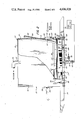
- FIG. 1 is a fragmentary perspective view of an electrostatic fluidized bed coating unit embodying the present invention, with portions broken away to illustrate internal structure and phenomena taking place therewithin, and showing a rectangular conductor being coated during passage therethrough;
- FIG. 2 is a side elevational view of the coating unit of FIG. 1, drawn to slightly different proportions and in partial section to illustrate details of construction;
- FIG. 3 is a downstream end view of the unit of the foregoing Figures, corresponding to the left side thereof and drawn to the scale of FIG. 2;
- FIG. 4 is an elevational view of one of the vortex-creating nozzle devices employed in the coating unit, taken in partial section and drawn to a greatly enlarged scale;
- FIG. 5 is a diagrammatical elevational view of a wire coating system incorporating the unit of the foregoing Figures.
- FIG. 6 is an enlarged sectional view of the structure provided at the bottom of the housing for connecting the gas and power supplies thereto.
- an electrostatic fluidized bed coating unit embodying the present invention includes a rectangular housing; although for convenience the housing is shown as one piece in FIG. 1, a more practical construction is illustrated in FIG. 2, consisting of an external enclosure, generally designated by the numeral 10, and an internal base generally designated by the numeral 12.
- the enclosure 10 consists of upstream and downstream end walls 14 and 15, respectively, and sidewalls 16; a separate removable cover plate 18 is provided, normally being secured in place by a plurality of screws 20.
- An aperture 22 is formed through the cover plate 18, and a coupling piece 24 extends thereabout for connection into a vacuumized powder recovery system (not shown).
- the end walls 14, 15 have relatively large openings 26 therein, which are aligned with one another and will normally be disposed on a horizontal axis when the unit is in operative position.
- a vortex nozzle device mounted within each of the openings 26 is a vortex nozzle device, generally designated by the numeral 28; the nozzle devices will be described in fuller detail hereinbelow.
- a short cylindrical sleeve element 30 extends through the end wall 14 at a level below the vortex device 28, and serves to mount a fluidic sensor (not shown), conventionally used in a unit of this type to determine and ensure (such as by feed-back control) the adequacy of the supply of coating powder.
- a fill tube 32 which will normally be connected into a powder recovery system for delivery of the coating material to the bed.
- a pair of supporting beams 34 are attached along each side at the bottom of the enclosure 10, the assembly being strengthened by vertically extending buttresses 36, attached to the sidewalls 16 thereabove. The ends of the beams 34 are configured and prepared for convenient mounting of the unit within a suitable framework.
- the base 12 of the housing also consists of integral end wall portions 38 and sidewall portions 40 (only one of each of which is visible in FIG. 2), which are dimensioned and configured to fit snugly within the opening formed at the lower end of the enclosure 10; as can be seen, the walls 38, 40 of the base 12 are relatively low, and extend only part way into the enclosure.
- An internal horizontal wall or plate 42 spans the bottom of the base section 12, and defines (with the bottom wall 43) a lower plenum 44 therebeneath and an upper plenum 46 thereabove.
- the plate 42 is made of non-conductive plastic, and has an elongated, rectilnear slot 48 extending along the major portion of its length, which is aligned on the longitudinal centerline of the unit.
- a wire brush electrode, generally designated by the numeral 50 is mounted within the slot 48; it too will be described more fully below.
- a porous support plate 52 Seated upon the upper edge of the peripheral wall formation (provided by the end walls 30 and sidewalls 40 of the base 12) is a porous support plate 52, which is dimensioned and configured to span the unit horizontally; the plate is of conventional construction for an electrostatic fluidized bed unit of this type, and defines the interface between the upper plenum 46 and the coating chamber 64 within the enclosure 10.
- Frame-like gasket pieces 54 extend about the periphery of the support plate 52 for sealing purposes, and the three parts are clamped in place between the upper edge of the base wall formation and the lower edge the shoulder formation 56, which projects inwardly from about the periphery of the enclosure.
- the two sections 10, 12 are secured together by a plurality of plastic (e.g., nylon) nut and bolt fasteners 58, which are accommodated by slots 60 formed at suitable locations along the sides and ends of the enclosure 10, and pass through holes formed therein and in the peripheral flange portion 62, which extends about the bottom of the base section 12.
- plastic e.g., nylon
- the sleeve 30 is disposed to position the fluidic sensor directly above the porous support plate 52, and that the inner end of the fill tube 32 is also disposed to deposit the powder directly upon its upper surface.
- a unique feature of the unit resides in the construction and placement of the brush electrode 50. As mentioned above, it is disposed on the longitudinal centerline of the housing (directly under the workpiece travel path) and effectively provides the sole means for electrostatically charging the particles of the coating material. It will also be noted that the individual wires (unnumbered) of which the electrode 50 is constructed are progressively shorter in the downstream direction of coating (i.e., from end wall 14 to end wall 15), giving it a tapered configuration when viewed laterally, as in FIG. 2. With earlier, uniform-height electrode configurations, it was observed that the initial section of the bed did not produce a deposit upon a moving workpiece at rates comparable to those achieved at locations further downstream.
- the wire bristles of the electrode member 50 are supported upon an underlying metal channel piece 66 which, in turn, is mounted upon the plate 42 by angle brackets 68 at its opposite ends.
- a short cylindrical post 70 projects downwardly midway along the length of channel piece 66, and (as seen in FIG. 6) has a bore 71 formed therethrough with a conical entrace portion. The bore is adapted to receive the male plug portion (or spade end) of a connecting jack 73 (e.g., a so-called "Jones plug”), enabling connection of the power cable 75 to the electrode 50 by a simple plug-in action.
- a connecting jack 73 e.g., a so-called "Jones plug
- the cable 75 extends through a plastic insulating sleeve 72, which is secured upon the post 70 and extends downwardly through the tubular extension 74 on the bottom wall 43.
- a connecting tee 76 is mounted upon the end of the extension 74, and has male connectors 78, 80 thereon.
- the connector 78 serves to receive an air supply hose (not shown) and the connector 80 is adapted to engage a conduit for the power cable 75.
- the unit operates by applying an appropriate voltage to the electrode 50 through the cable 75, while introducing air under pressure into the lower plenum 44 through the tube 74.
- the channel piece 66 is slightly narrower than the slot 48, permitting the air to flow through the gaps formed along the lateral edges thereof. As it does so, it comes into direct contact with the free outer end portions of the bristles of the electrode 50, causing the air to be ionized in a highly efficient manner due to the concentration of charges (normally producing a corona effect) thereat.
- the ionized air then passes through the upper plenum 46 and the porous plate 52, to simultaneously fluidize and electrostatically charge the powder of the bed 98 supported thereupon.
- the powder is attracted to and deposited upon the workpiece conveyed through the coating chamber 64 (normally at ground potential), in a manner that is now conventional and disclosed in certain of the prior art patents listed above, particularly Knudsen Pat. No. 3,916,826.
- a generally toroidal nozzle device 28 is employed at each end of the unit to discharge air inwardly of the coating chamber 64 along a helical path.
- the devices at the opposite ends differ only in the axial direction of air discharge, and are related to one another in mirror image fashion; accordingly only one need be described in detail.
- the nozzle device 28 consists of two shell sections 82, 84, cooperatively defining a toroidal internal passage 86 having a tapered, circumferential throat section 88 between the curved circular lips 87, 89, leading to a continuous circular discharge orifice 90; the aperture 98 through the center of the device 28 serves to permit passage of the workpiece.
- Extending into the passage 86 is an inlet tube 92, which intersects therewith in a generally tangential relationship; the outer end of the tube 92 is provided with a coupling piece 94 for attachment to a source of air under pressure.
- Three tabs 96 project radially from the outer periphery of the section 84, and provide the means by which the device is attached to the associated end wall 14, 15 of the closure 10, within the circular openings 26 thereof.
- fluidization and electrostatic charging of the bed of powder 98 within the chamber 64 creates a cloud of particles under the influence of an electrostatic force field that extends generally vertically from the electrode 50 toward the workpiece 100, which is shown as a rectangular wire (the directional characterization of the force field will of course depend upon whether the electrode is charged negatively or positively, and is per se of no consequence to the invention).
- the air issuing from the two nozzle devices 28 proceeds inwardly from the opposite ends of the unit in the same direction of rotation (clockwise as viewed from the left side of FIG. 1) to provide a helical air flow path forming a vortex 102 about, and substantially coaxial with, the wire 100.
- the particles of coating material lifted from the bed 98 by the fluidizing air, and comprising the cloud thereabove become entrained in the helical flow of air issuing from the vortex devices 28 and swirl about the workpiece 100, to which they will readily be attracted by electrostatic forces existing therebetween.
- the suspension of the powder particles in the vortex provides a highly homogeneous secondary cloud surrounding the workpiece; the cloud has fairly well-defined boundaries which are visably discernable in the absence of the grounded workpiece.
- This homogeneity is believed to exit not only with respect to partical size distribution and density, but also as to the value of the charge on the individual particles.
- the particles evidently acquire, through redistribution of electrons resulting from contact with and/or inductive influence upon one another, charges that are of virtually the same magnitude. It is believed that the extraordinarily uniform nature of the coating produced upon the workpiece is attributable primarily to these combined effects, which cause all surface of the workpiece to begin to coat at virtually the same time and the same rate.
- the vortex appears to define therewithin a secondary electrostatic field, as can be confirmed by actual measurements, which indicate the existence of a magnetic field oriented longitudinally to its axis.
- the field within the vortex seems to be effectively isolated from the vertical field produced by the electrode 50, as well as from external electrical influences (e.g., noise, static, and the like), which if not so dampened tend to produce small but significant variations in the thickness of the build, such as along the length of a wire.
- the lines of force of the the secondary field are believed to be substantially radial with respect to the workpiece 100, and normal to the surface of vortex (as indicated by the arrows within the vortex in FIG. 1), and this effect is also believed to contribute very significantly to the high degree of uniformity in the deposit produced.
- the system also conveniently includes wire supply and take-up rolls, generally designated by the numerals 104 and 106, the strand of conductor 100 being played off from the supply roll 104 and wound upon the take-up roll 106 (shown here to be grounded, to effect grounding of the conductor), after passing through the fluidization chamber 64 of the coater.
- powder recovery and recycle means will normally also be included in the system, and the conduit 116 is provided for conducting powder withdrawn to a collection unit.
- nozzle devices 28 shown for creating a helical gas flow will be preferred in most instances, it will be understood that different means may be employed for creating a circumferential and longitudinally progressing flow about the workpiece.
- different means may be employed for creating a circumferential and longitudinally progressing flow about the workpiece.
- nozzles or other injection devices appropriately configured or disposed for that purpose will be substituted.
- the use of a vortex device at each of the opposite ends of the coating chamber will produce best results, this may not be necessary in all instances; e.g., when the path length is relatively short the provision of such a device at only one end may suffice.
- the diameter (or transverse dimensions) of the vortex may vary considerably, and will depend largely upon the nature of the workpiece being coated. In a typical example, for a coating unit of the type illustrated, the diameter at the ends of the vortex may be about two and one-half inches, increasing to about five inches in the center.
- Another unique feature of the invention resides in the fact that the position of the workpiece within the vortex may be varied considerably without material effect upon the nature of the coating produced. Whereas the travel path will be generally parallel to the axis of the vortex it can deviate considerably from a coaxial relationship, as long as the workpiece remains within the secondary cloud.
- the location of the workpiece within the coating chamber will often have a crucial effect upon the build; this has traditionally imposed limitations for avoiding excessive lateral and (especially) vertical displacement of the substrate from the intended path.
- the coating unit of the invention is virtually free of metal parts. This has not been the case in prior equipment in which plenum mounted electrodes have been used to produce ionized air, in which cases the mounting plate (such as 42 in the drawings) was itself conventionally made of metal.
- the elimination of metal structure within and on the unit has been found to contribute significantly to the ability to regulate the characteristics of the electrostatic fields produced within the unit, and hence the charge upon the particles. It is believed that these advantages are attributable to the elimination of capacitance, and of the consequential periodic accumulation and discharge of electrical energy during operation of the unit.
- the provision of a unit that is constructed virtually entirely of dielectric materials represents a further advance in the art, in addition to the other beneficial aspects of the invention discussed in detail hereinabove.
- the fluidizing gas normally air
- the fluidizing gas will be introduced into the lower plenum at a rate sufficient to provide about seven to eight cubic feet per minute of air, per square foot of bed cross-sectional area (typically three to four square feet, in a unit such as that illustrated).
- the vortex-creating air will typically be injected at a rate of 75 to 100 cubic feet per hour, to discharge with an angular velocity of about 500 to 3000 feet per minute and a lineal velocity of about 50 to 300 feet per minute.
- the voltage applied to the electrode will usually be in the range of about 40 to 50 kilovolts, and it will be appreciated that this represents a significant decrease from prior practice, wherein potentials of 70 to 80 kilovolts were most common.
- Wire conductors and other elongated workpieces can generally be coated at rates of about 25 to 150 feet per minute, and builds of the coating material ranging from 2 to 40 mils (i.e., 1 to 20 mils in thickness) can readily be achieved with high levels of uniformity. It should be appreciated that the indicated upper speed value of 150 feet per minute is attributable to the capacity of the heating units normally used to effect fusion of the particulate coating material, rather than to limitations of the coating equipment. That is to say, production speeds will undoubtedly increase as more efficient means for integrating the deposits becomes available.
- the vortex of charged particles may be produced by other means, such as by using suitably designed nozzles disposed along the workpiece travel path to produce the necessary helical flow thereabout.
- the apparatus, system and method of the invention are particularly well suited for the coating of continuous length workpieces, such as round and rectangular wire, metal strip, screen, and the like, they may be employed to good advantage for coating individual articles (elongated or not) of a wide variety of types.
- Virtually any particulate or finely divided material that is capable of receiving and retaining an electrostatic charge may be used in the practice of the invention; however, the powder should, in addition, be capable of fluidizing well at an air flow rate of not less than about five cubic feet per minute, per square foot of bed (or porous support plate) area.
- Such materials are well known and constitute an extensive list, including both inorganic and organic resins, the latter typically being a polyolefin, an ethylenically unsaturated hydrocarbon polymer, an acrylic polymer, an epoxy resin, or the like; the coating material employed will normally have a particle size ranging from about 20 to 75 microns, with a bell-shaped curve distribution.
- the present invention provides a novel method, apparatus, and system by which workpieces, and particularly conductors of continuous length, can be coated quickly, efficiently, safely, and with an exceptionally high degree of uniformity in the build.
- the nature of the coating produced can readily be controlled by the speed of the workpiece and the magnitude of the voltage applied, and the effects of workpiece position within the cloud of charged particles and of external electrical effects are minimized.
- Coating can be carried out at voltage levels that are significantly reduced from those heretofore employed for practical high-speed operation, thereby enhancing safety, and the economy of production is maximized by the significant reduction of waste produced during start-up and discontinuances of operation; the coating unit is uncomplicated and relatively inexpensive to manufacture and operate.
Abstract
Description
Claims (24)
Priority Applications (9)
| Application Number | Priority Date | Filing Date | Title |
|---|---|---|---|
| US06/708,989 US4606928A (en) | 1985-03-07 | 1985-03-07 | Vortex effect electrostatic fluidized bed coating method and apparatus |
| EP86902125A EP0214280B1 (en) | 1985-03-07 | 1986-03-05 | Vortex effect electrostatic fluidized bed coating method and apparatus |
| DE8686902125T DE3668562D1 (en) | 1985-03-07 | 1986-03-05 | METHOD AND DEVICE FOR COATING WITH A FLUID BED AND PRETEX EFFECT. |
| PCT/US1986/000466 WO1986005127A1 (en) | 1985-03-07 | 1986-03-05 | Vortex effect electrostatic fluidized bed coating method and apparatus |
| AU56255/86A AU583109B2 (en) | 1985-03-07 | 1986-03-05 | Vortex effect electrostatic fluidized bed coating method and apparatus |
| JP50172586A JPH0636892B2 (en) | 1985-03-07 | 1986-03-05 | Vortex effect electrostatic fluidized bed coating method and apparatus |
| AT86902125T ATE49908T1 (en) | 1985-03-07 | 1986-03-05 | METHOD AND DEVICE FOR COATING WITH FLUID BED AND VORTEX EFFECT. |
| CA000503460A CA1238818A (en) | 1985-03-07 | 1986-03-06 | Vortex effect electrostatic fluidized bed coating method and apparatus |
| NO864434A NO864434L (en) | 1985-03-07 | 1986-11-06 | METHOD AND APPARATUS FOR COATING WITH ANTURAL EFFECT ELECTROSTATIC FLUIDIZED RENT. |
Applications Claiming Priority (1)
| Application Number | Priority Date | Filing Date | Title |
|---|---|---|---|
| US06/708,989 US4606928A (en) | 1985-03-07 | 1985-03-07 | Vortex effect electrostatic fluidized bed coating method and apparatus |
Publications (1)
| Publication Number | Publication Date |
|---|---|
| US4606928A true US4606928A (en) | 1986-08-19 |
Family
ID=24848020
Family Applications (1)
| Application Number | Title | Priority Date | Filing Date |
|---|---|---|---|
| US06/708,989 Expired - Lifetime US4606928A (en) | 1985-03-07 | 1985-03-07 | Vortex effect electrostatic fluidized bed coating method and apparatus |
Country Status (7)
| Country | Link |
|---|---|
| US (1) | US4606928A (en) |
| EP (1) | EP0214280B1 (en) |
| JP (1) | JPH0636892B2 (en) |
| AU (1) | AU583109B2 (en) |
| CA (1) | CA1238818A (en) |
| DE (1) | DE3668562D1 (en) |
| WO (1) | WO1986005127A1 (en) |
Cited By (11)
| Publication number | Priority date | Publication date | Assignee | Title |
|---|---|---|---|---|
| US4808432A (en) * | 1986-08-18 | 1989-02-28 | Electrostatic Technology Incorporated | Electrostatic coating apparatus and method |
| US4990359A (en) * | 1989-11-13 | 1991-02-05 | Nordson Corporation | Electrostatic method for coating redistribution |
| WO1995032809A1 (en) * | 1994-05-26 | 1995-12-07 | Electrostatic Technology, Inc. | Vertical electrostatic coater having vortex effect |
| US5836925A (en) * | 1996-04-03 | 1998-11-17 | Soltesz; Peter P. | Catheter with variable flexibility properties and method of manufacture |
| US6068702A (en) * | 1998-03-13 | 2000-05-30 | Nordson Corporation | Powder coating apparatus for use in multiple powder coating techniques |
| US6240873B1 (en) | 1998-11-20 | 2001-06-05 | Wordson Corporation | Annular flow electrostatic powder coater |
| US6528125B1 (en) * | 1999-06-08 | 2003-03-04 | Itt Manufacturing Enterprises, Inc. | Corrosion resistant powder coated metal tube and process for making the same |
| US6620243B1 (en) | 1998-05-29 | 2003-09-16 | Nordson Corporation | Fluidized bed powder handling and coating apparatus and methods |
| US20070005037A1 (en) * | 2005-06-29 | 2007-01-04 | Mansfield Todd L | Disposable absorbent article containing an unapertured skinless elastomeric layer |
| US20080171135A1 (en) * | 2007-01-16 | 2008-07-17 | Burch Jerry C | Method and apparatus for powder coating stator stacks |
| US20080220664A1 (en) * | 2006-07-03 | 2008-09-11 | Hall David R | Wiper for Tool String Direct Electrical Connection |
Citations (25)
| Publication number | Priority date | Publication date | Assignee | Title |
|---|---|---|---|---|
| US2421787A (en) * | 1945-01-26 | 1947-06-10 | Harper J Ransburg Company | Electrostatic coating method |
| US2777784A (en) * | 1951-11-27 | 1957-01-15 | Ransburg Electro Coating Corp | Method and apparatus for spray coating of articles |
| US3108022A (en) * | 1960-05-09 | 1963-10-22 | Polymer Processes Inc | Apparatus for coating an elongate body with fluidized coating material |
| US3155545A (en) * | 1961-02-27 | 1964-11-03 | Rheem Mfg Co | Apparatus for external coating of objects |
| US3248253A (en) * | 1962-06-22 | 1966-04-26 | Sames Sa De Machines Electrost | Electrostatic transfer method and apparatus for coating articles with a fluidized composition |
| US3326182A (en) * | 1963-06-13 | 1967-06-20 | Inoue Kiyoshi | Electrostatic spray device and method |
| US3396699A (en) * | 1966-10-21 | 1968-08-13 | Anaconda Wire & Cable Co | Continuous coating apparatus |
| US3439649A (en) * | 1965-03-15 | 1969-04-22 | Ransburg Electro Coating Corp | Electrostatic coating apparatus |
| US3476081A (en) * | 1964-03-25 | 1969-11-04 | United States Steel Corp | Fluidizing chamber |
| US3566833A (en) * | 1968-06-28 | 1971-03-02 | Anaconda Wire & Cable Co | Continuous coating apparatus |
| US3607998A (en) * | 1969-04-07 | 1971-09-21 | Walter R Goodridge | Method for producing hollow articles |
| US3828729A (en) * | 1972-05-18 | 1974-08-13 | Electrostatic Equip Corp | Electrostatic fluidized bed |
| US3834927A (en) * | 1971-07-16 | 1974-09-10 | Koerper Eng Ass Inc | Fluidized bed coating method |
| US3916826A (en) * | 1973-09-18 | 1975-11-04 | Electrostatic Equip Corp | Electrostatic coating apparatus |
| US4011832A (en) * | 1975-02-26 | 1977-03-15 | Westinghouse Electric Corporation | Build control for fluidized bed wire coating |
| US4030446A (en) * | 1976-04-30 | 1977-06-21 | Electrostatic Equipment Corporation | Directed flow ionization chamber in electrostatic coating |
| US4034703A (en) * | 1975-09-25 | 1977-07-12 | Metallgesellschaft Aktiengesellschaft | Apparatus for externally coating endless metal tubing and like elongated metal members |
| US4051809A (en) * | 1976-09-22 | 1977-10-04 | Westinghouse Electric Corporation | Apparatus for cleaning and coating an elongated metallic member |
| US4084019A (en) * | 1976-02-05 | 1978-04-11 | Armco Steel Corporation | Electrostatic coating grid and method |
| US4297386A (en) * | 1980-01-23 | 1981-10-27 | Electrostatic Equipment Corporation | Control grid in electrostatic fluidized bed coater |
| US4329377A (en) * | 1979-07-30 | 1982-05-11 | Felten & Guilleaume Carlswerk Aktiengesellschaft | Process for coating wire with insulation |
| US4330567A (en) * | 1980-01-23 | 1982-05-18 | Electrostatic Equipment Corp. | Method and apparatus for electrostatic coating with controlled particle cloud |
| US4332835A (en) * | 1980-12-23 | 1982-06-01 | Electrostatic Equipment Corp. | Plenum mounted grid for electrostatic fluidized bed |
| US4418642A (en) * | 1981-11-20 | 1983-12-06 | Electrostatic Equipment Corporation | Build control apparatus and method |
| US4472452A (en) * | 1981-11-20 | 1984-09-18 | Electrostatic Equipment Corp. | Build control apparatus and method |
-
1985
- 1985-03-07 US US06/708,989 patent/US4606928A/en not_active Expired - Lifetime
-
1986
- 1986-03-05 WO PCT/US1986/000466 patent/WO1986005127A1/en active IP Right Grant
- 1986-03-05 AU AU56255/86A patent/AU583109B2/en not_active Ceased
- 1986-03-05 DE DE8686902125T patent/DE3668562D1/en not_active Expired - Lifetime
- 1986-03-05 EP EP86902125A patent/EP0214280B1/en not_active Expired
- 1986-03-05 JP JP50172586A patent/JPH0636892B2/en not_active Expired - Lifetime
- 1986-03-06 CA CA000503460A patent/CA1238818A/en not_active Expired
Patent Citations (25)
| Publication number | Priority date | Publication date | Assignee | Title |
|---|---|---|---|---|
| US2421787A (en) * | 1945-01-26 | 1947-06-10 | Harper J Ransburg Company | Electrostatic coating method |
| US2777784A (en) * | 1951-11-27 | 1957-01-15 | Ransburg Electro Coating Corp | Method and apparatus for spray coating of articles |
| US3108022A (en) * | 1960-05-09 | 1963-10-22 | Polymer Processes Inc | Apparatus for coating an elongate body with fluidized coating material |
| US3155545A (en) * | 1961-02-27 | 1964-11-03 | Rheem Mfg Co | Apparatus for external coating of objects |
| US3248253A (en) * | 1962-06-22 | 1966-04-26 | Sames Sa De Machines Electrost | Electrostatic transfer method and apparatus for coating articles with a fluidized composition |
| US3326182A (en) * | 1963-06-13 | 1967-06-20 | Inoue Kiyoshi | Electrostatic spray device and method |
| US3476081A (en) * | 1964-03-25 | 1969-11-04 | United States Steel Corp | Fluidizing chamber |
| US3439649A (en) * | 1965-03-15 | 1969-04-22 | Ransburg Electro Coating Corp | Electrostatic coating apparatus |
| US3396699A (en) * | 1966-10-21 | 1968-08-13 | Anaconda Wire & Cable Co | Continuous coating apparatus |
| US3566833A (en) * | 1968-06-28 | 1971-03-02 | Anaconda Wire & Cable Co | Continuous coating apparatus |
| US3607998A (en) * | 1969-04-07 | 1971-09-21 | Walter R Goodridge | Method for producing hollow articles |
| US3834927A (en) * | 1971-07-16 | 1974-09-10 | Koerper Eng Ass Inc | Fluidized bed coating method |
| US3828729A (en) * | 1972-05-18 | 1974-08-13 | Electrostatic Equip Corp | Electrostatic fluidized bed |
| US3916826A (en) * | 1973-09-18 | 1975-11-04 | Electrostatic Equip Corp | Electrostatic coating apparatus |
| US4011832A (en) * | 1975-02-26 | 1977-03-15 | Westinghouse Electric Corporation | Build control for fluidized bed wire coating |
| US4034703A (en) * | 1975-09-25 | 1977-07-12 | Metallgesellschaft Aktiengesellschaft | Apparatus for externally coating endless metal tubing and like elongated metal members |
| US4084019A (en) * | 1976-02-05 | 1978-04-11 | Armco Steel Corporation | Electrostatic coating grid and method |
| US4030446A (en) * | 1976-04-30 | 1977-06-21 | Electrostatic Equipment Corporation | Directed flow ionization chamber in electrostatic coating |
| US4051809A (en) * | 1976-09-22 | 1977-10-04 | Westinghouse Electric Corporation | Apparatus for cleaning and coating an elongated metallic member |
| US4329377A (en) * | 1979-07-30 | 1982-05-11 | Felten & Guilleaume Carlswerk Aktiengesellschaft | Process for coating wire with insulation |
| US4297386A (en) * | 1980-01-23 | 1981-10-27 | Electrostatic Equipment Corporation | Control grid in electrostatic fluidized bed coater |
| US4330567A (en) * | 1980-01-23 | 1982-05-18 | Electrostatic Equipment Corp. | Method and apparatus for electrostatic coating with controlled particle cloud |
| US4332835A (en) * | 1980-12-23 | 1982-06-01 | Electrostatic Equipment Corp. | Plenum mounted grid for electrostatic fluidized bed |
| US4418642A (en) * | 1981-11-20 | 1983-12-06 | Electrostatic Equipment Corporation | Build control apparatus and method |
| US4472452A (en) * | 1981-11-20 | 1984-09-18 | Electrostatic Equipment Corp. | Build control apparatus and method |
Non-Patent Citations (2)
| Title |
|---|
| Webster s New Collegiate Dictionary, 1975, G & C Merriam Co., p. 1313. * |
| Webster's New Collegiate Dictionary, ©1975, G & C Merriam Co., p. 1313. |
Cited By (22)
| Publication number | Priority date | Publication date | Assignee | Title |
|---|---|---|---|---|
| US4808432A (en) * | 1986-08-18 | 1989-02-28 | Electrostatic Technology Incorporated | Electrostatic coating apparatus and method |
| US4990359A (en) * | 1989-11-13 | 1991-02-05 | Nordson Corporation | Electrostatic method for coating redistribution |
| WO1995032809A1 (en) * | 1994-05-26 | 1995-12-07 | Electrostatic Technology, Inc. | Vertical electrostatic coater having vortex effect |
| US5773097A (en) * | 1994-05-26 | 1998-06-30 | Nordson Corporation | Vertical electrostatic coater having vortex effect |
| US5836925A (en) * | 1996-04-03 | 1998-11-17 | Soltesz; Peter P. | Catheter with variable flexibility properties and method of manufacture |
| US6068702A (en) * | 1998-03-13 | 2000-05-30 | Nordson Corporation | Powder coating apparatus for use in multiple powder coating techniques |
| US6620243B1 (en) | 1998-05-29 | 2003-09-16 | Nordson Corporation | Fluidized bed powder handling and coating apparatus and methods |
| US20040219301A1 (en) * | 1998-11-20 | 2004-11-04 | Nordson Corporation | Electrostatic powder coating apparatus using a swirling flow pattern |
| US6458427B2 (en) * | 1998-11-20 | 2002-10-01 | Nordson Corporation | Annular flow electrostatic powder coater |
| US6582521B2 (en) | 1998-11-20 | 2003-06-24 | Nordson Corporation | Annular flow electrostatic powder coater |
| US6240873B1 (en) | 1998-11-20 | 2001-06-05 | Wordson Corporation | Annular flow electrostatic powder coater |
| US20030203121A1 (en) * | 1998-11-20 | 2003-10-30 | Nordson Corporation | Annular flow electrostatic powder coater |
| US6759095B2 (en) * | 1998-11-20 | 2004-07-06 | Nordson Corporation | Electrostatic powder coating method using a swirling flow pattern |
| US6913213B2 (en) | 1998-11-20 | 2005-07-05 | Nordson Corporation | Electrostatic powder coating apparatus using a swirling flow pattern |
| US6528125B1 (en) * | 1999-06-08 | 2003-03-04 | Itt Manufacturing Enterprises, Inc. | Corrosion resistant powder coated metal tube and process for making the same |
| US20070005037A1 (en) * | 2005-06-29 | 2007-01-04 | Mansfield Todd L | Disposable absorbent article containing an unapertured skinless elastomeric layer |
| EP2110107A1 (en) | 2005-06-29 | 2009-10-21 | The Procter and Gamble Company | Disposable absorbent article containing an unapertured skinless elastomer layer |
| US8187243B2 (en) | 2005-06-29 | 2012-05-29 | The Procter & Gamble Company | Disposable absorbent article containing an unapertured skinless elastomeric layer |
| US9554947B2 (en) | 2005-06-29 | 2017-01-31 | The Procter & Gamble Company | Disposable absorbent article containing an unapertured skinless elastomeric layer |
| US20080220664A1 (en) * | 2006-07-03 | 2008-09-11 | Hall David R | Wiper for Tool String Direct Electrical Connection |
| US20080171135A1 (en) * | 2007-01-16 | 2008-07-17 | Burch Jerry C | Method and apparatus for powder coating stator stacks |
| US7981465B2 (en) | 2007-01-16 | 2011-07-19 | Globe Motors, Inc. | Method and apparatus for powder coating stator stacks |
Also Published As
| Publication number | Publication date |
|---|---|
| JPH0636892B2 (en) | 1994-05-18 |
| AU5625586A (en) | 1986-09-24 |
| WO1986005127A1 (en) | 1986-09-12 |
| DE3668562D1 (en) | 1990-03-08 |
| EP0214280B1 (en) | 1990-01-31 |
| JPS62502313A (en) | 1987-09-10 |
| EP0214280A4 (en) | 1987-07-06 |
| EP0214280A1 (en) | 1987-03-18 |
| AU583109B2 (en) | 1989-04-20 |
| CA1238818A (en) | 1988-07-05 |
Similar Documents
| Publication | Publication Date | Title |
|---|---|---|
| US4606928A (en) | Vortex effect electrostatic fluidized bed coating method and apparatus | |
| CA1244299A (en) | Spraying apparatus | |
| US4106697A (en) | Spraying device with gas shroud and electrostatic charging means having a porous electrode | |
| US6458427B2 (en) | Annular flow electrostatic powder coater | |
| US4343433A (en) | Internal-atomizing spray head with secondary annulus suitable for use with induction charging electrode | |
| US4215818A (en) | Induction charging electrostatic spraying device and method | |
| US4545536A (en) | Apparatus for electrostatic paint spraying | |
| EP0230341B1 (en) | Electrostatic spray nozzle | |
| CZ112486A3 (en) | Process and apparatus for applying coatings to articles by liquid spraying | |
| US3130066A (en) | Electro spray apparatus and method | |
| US5773097A (en) | Vertical electrostatic coater having vortex effect | |
| US4541844A (en) | Method and apparatus for dielectrophoretically enhanced particle collection | |
| US3566833A (en) | Continuous coating apparatus | |
| US3342415A (en) | Electrostatic coating system | |
| US4084019A (en) | Electrostatic coating grid and method | |
| US3117029A (en) | Electrostatic coating | |
| JPH0330848A (en) | Method and apparatus for electrostatic spray of liquid | |
| CA1269571A (en) | Electrostatic coating apparatus and method | |
| Marchewicz et al. | Electrostatic charging of water spray by induction | |
| US3049092A (en) | Apparatus for the electrostatic coating of articles | |
| KR830002693B1 (en) | sprayer | |
| JPS5939357A (en) | Apparatus for electrostatically coating wire body | |
| JPS5939356A (en) | Apparatus for electrostatically coating wire body | |
| WO2002078854A1 (en) | Device for electrostatic coating with a double slit for emitting powder, in particular for coating metal coils | |
| SU939125A1 (en) | Liquid spraying method |
Legal Events
| Date | Code | Title | Description |
|---|---|---|---|
| AS | Assignment |
Owner name: ELECTROSTATIC TECHNOLOGY INCORPORATED, 80 HAMILTON Free format text: ASSIGNMENT OF ASSIGNORS INTEREST.;ASSIGNORS:DUNFORD, WILLIAM J.;HAJEK, BEDRICH;REEL/FRAME:004380/0960 Effective date: 19850305 |
|
| STCF | Information on status: patent grant |
Free format text: PATENTED CASE |
|
| CC | Certificate of correction | ||
| AS | Assignment |
Owner name: CITYTRUST, 961 MAIN STREET, BRIDGEPORT, CT Free format text: SECURITY INTEREST;ASSIGNOR:ELECTROSTATIC EQUIPMENT CORP.;REEL/FRAME:005006/0950 Effective date: 19880830 |
|
| FEPP | Fee payment procedure |
Free format text: PAT HLDR NO LONGER CLAIMS SMALL ENT STAT AS SMALL BUSINESS (ORIGINAL EVENT CODE: LSM2); ENTITY STATUS OF PATENT OWNER: LARGE ENTITY Free format text: PAYOR NUMBER ASSIGNED (ORIGINAL EVENT CODE: ASPN); ENTITY STATUS OF PATENT OWNER: LARGE ENTITY |
|
| FPAY | Fee payment |
Year of fee payment: 4 |
|
| AS | Assignment |
Owner name: ELECTROSTATIC TECHNOLOGY, INC. Free format text: RELEASED BY SECURED PARTY;ASSIGNOR:CITYTRUST, A CT STATE BANK AND TRUST COMPANY;REEL/FRAME:005243/0126 Effective date: 19890510 |
|
| AS | Assignment |
Owner name: E. T. TECH ACQUISITION CORP., CONNECTICUT Free format text: ASSIGNMENT OF ASSIGNORS INTEREST.;ASSIGNOR:SL ELECTROSTATIC TECHNOLOGY, INC.;REEL/FRAME:006284/0078 Effective date: 19921019 |
|
| FEPP | Fee payment procedure |
Free format text: PAT HOLDER CLAIMS SMALL ENTITY STATUS - SMALL BUSINESS (ORIGINAL EVENT CODE: SM02); ENTITY STATUS OF PATENT OWNER: LARGE ENTITY |
|
| FPAY | Fee payment |
Year of fee payment: 8 |
|
| AS | Assignment |
Owner name: ELECTROSTATIC TECHNOLOGY, INC., CONNECTICUT Free format text: CHANGE OF NAME;ASSIGNOR:E.T. TECH ACQUISITION CORP;REEL/FRAME:008022/0302 Effective date: 19920918 |
|
| FEPP | Fee payment procedure |
Free format text: PAT HLDR NO LONGER CLAIMS SMALL ENT STAT AS SMALL BUSINESS (ORIGINAL EVENT CODE: LSM2); ENTITY STATUS OF PATENT OWNER: LARGE ENTITY Free format text: PAYER NUMBER DE-ASSIGNED (ORIGINAL EVENT CODE: RMPN); ENTITY STATUS OF PATENT OWNER: LARGE ENTITY |
|
| FPAY | Fee payment |
Year of fee payment: 12 |