US4608487A - Input unit of an automatic vending machine - Google Patents
Input unit of an automatic vending machine Download PDFInfo
- Publication number
- US4608487A US4608487A US06/592,410 US59241084A US4608487A US 4608487 A US4608487 A US 4608487A US 59241084 A US59241084 A US 59241084A US 4608487 A US4608487 A US 4608487A
- Authority
- US
- United States
- Prior art keywords
- bar
- vending machine
- automatic vending
- bar code
- codes
- Prior art date
- Legal status (The legal status is an assumption and is not a legal conclusion. Google has not performed a legal analysis and makes no representation as to the accuracy of the status listed.)
- Expired - Lifetime
Links
Images


Classifications
-
- G—PHYSICS
- G07—CHECKING-DEVICES
- G07F—COIN-FREED OR LIKE APPARATUS
- G07F5/00—Coin-actuated mechanisms; Interlocks
-
- G—PHYSICS
- G06—COMPUTING; CALCULATING OR COUNTING
- G06K—GRAPHICAL DATA READING; PRESENTATION OF DATA; RECORD CARRIERS; HANDLING RECORD CARRIERS
- G06K7/00—Methods or arrangements for sensing record carriers, e.g. for reading patterns
- G06K7/10—Methods or arrangements for sensing record carriers, e.g. for reading patterns by electromagnetic radiation, e.g. optical sensing; by corpuscular radiation
- G06K7/10544—Methods or arrangements for sensing record carriers, e.g. for reading patterns by electromagnetic radiation, e.g. optical sensing; by corpuscular radiation by scanning of the records by radiation in the optical part of the electromagnetic spectrum
- G06K7/10821—Methods or arrangements for sensing record carriers, e.g. for reading patterns by electromagnetic radiation, e.g. optical sensing; by corpuscular radiation by scanning of the records by radiation in the optical part of the electromagnetic spectrum further details of bar or optical code scanning devices
- G06K7/10881—Methods or arrangements for sensing record carriers, e.g. for reading patterns by electromagnetic radiation, e.g. optical sensing; by corpuscular radiation by scanning of the records by radiation in the optical part of the electromagnetic spectrum further details of bar or optical code scanning devices constructional details of hand-held scanners
-
- G—PHYSICS
- G07—CHECKING-DEVICES
- G07F—COIN-FREED OR LIKE APPARATUS
- G07F5/00—Coin-actuated mechanisms; Interlocks
- G07F5/20—Coin-actuated mechanisms; Interlocks specially adapted for registering coins as credit, e.g. mechanically actuated
- G07F5/22—Coin-actuated mechanisms; Interlocks specially adapted for registering coins as credit, e.g. mechanically actuated electrically actuated
-
- G—PHYSICS
- G07—CHECKING-DEVICES
- G07F—COIN-FREED OR LIKE APPARATUS
- G07F9/00—Details other than those peculiar to special kinds or types of apparatus
- G07F9/001—Interfacing with vending machines using mobile or wearable devices
Definitions
- the present invention relates to an input unit which inputs the operation orders and set information, necessary to automatic sales operations, into an automatic vending machine.
- the automatic vending machine needs inputs of the operation orders and setting information.
- the display functions of the sales money-amount and the sales number are adapted to display on a display unit the sales total amount, the sales total number, which are calculated and stored for each of the sales operations, through the inputting of the operation orders for the sales money-amount and the sales number display.
- the multi-vending indicates a function of continuously selling a plurality of commodities within the inputted money amount.
- column alternation means a function of alternately discharging a commodity from each sales column each time the commodity is selected by a customer when the same kinds of commodities are accommodated within two columns or more.
- the set information as to which column used as column alternation is required to be inputted.
- the confirmation display of the set selling prices is adapted to display on the display unit the selling price, which has been set to the commodity of the column corresponding to the selection switch, when a selection switch is depressed in a condition where any coins have not been inputted into the automatic vending machine.
- a set information of "display" of the confirmation display is required to be inputted into the automatic vending machine.
- the vending test enables the commodities to be sold without the inputting of the coin.
- the operation instructions of the vending test and a set information for specifying a column to be vending-tested are required to be inputted.
- an operation order of the selling price setting and a selling price as a set information are required to be inputted even when the selling price is set with respect to the commodities for each column.
- the most common input unit of an automatic vending machine is a keyboard.
- a coin-operated Musical Machine for selecting and inputting a record performed by a keyboard is disclosed in U.S. Pat. No. 3,869,032 and U.S. Pat. No. 3,985,217.
- An Automatic Drink Dispensing Apparatus for selecting and inputting beverage to be fed by a keyboard is disclosed in U.S. Pat. No. 3,991,911.
- the operating procedure of the keyboard is so complicated that a user who is not used to the operation finds it difficult to operate the keyboard.
- An object of the present invention is to provide an input unit which is capable of easily inputting various operation orders and set information into an automatic vending machine.
- Another object of the present invention is to provide an input unit which is capable of easily coping with the changes in and the addition to the input contents.
- a further object of the present invention is to provide an input unit which is capable of easily and positively inputting the selling prices as the set information.
- a still further object of the present invention is to provide a smaller-sized input unit which is capable of remarkably reducing the signal harness for input use into an automatic vending machine.
- an input unit of an automatic vending machine comprising a bar sheet, wherein an operation order to be inputted into an automatic vending machine and set information, which is necessary for achieving an automatic sales operation, are printed by given bar codes
- a hand scanner type of bar code reader equipped with a light emitting element and a photoelectric conversion element
- said light emitting element is adapted to sequentially apply its light on bars or spaces through manual movement in accordance with the arrangement of the bars and spaces of said bar codes
- said photoelectric conversion element is adapted to detect the light reflection amount from said light emitting element to output electric signals corresponding to the pattern of the bar code
- means for converting said operation orders and said set information, shown by said digital signals, into codes which can be recognized by the automatic vending machine comprising a bar sheet, wherein an operation order to be inputted into an automatic vending machine and set information, which is necessary for achieving an automatic sales operation, are printed by given bar codes
- a hand scanner type of bar code reader equipped
- FIG. 1 is a functional block diagram showing an input unit of an automatic vending machine in accordance with the present invention
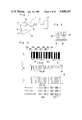
- FIGS. 2(a) to (c) show views showing bar code patterns, signal waveforms corresponding thereto, and codes, respectively;
- FIG. 3 is a cross-sectional view of the portions of a bar code reader
- FIG. 4 is an electric circuit diagram of the input unit
- FIG. 5A through FIG. 5C are flow charts for illustrating the operation of a microcomputer to be used in the input unit
- FIG. 6 is a flow chart for illustrating the operation during the interrupting operation of a microcomputer for input unit use
- FIG. 7 is a comparison table of the processing code between 9-bit code and 8-bit code
- FIG. 8A through FIG. 8E are tables describing an operation order or set information each showing the processing code
- FIG. 9 is a perspective view of an automatic vending machine
- FIG. 10 is an electric circuit diagram of a controlling circuit of an automatic vending machine provided with an input unit in accordance with the present invention.
- FIG. 11 is a flow chart for illustrating the operations of a microcomputer for controlling an automatic vending machine
- FIG. 12 is a sketch view showing one example of a bar sheet for use in selling price input
- FIG. 13 is a functional block diagram for illustrating the microcomputer during the inputting of the selling prices
- FIG. 14 shows signal wave-form views in a case where a bar code and a portion with selling prices are expressed thereon are rubbed by a bar code reader;
- FIG. 15 is a sketch view showing another example of a bar sheet to be used in selling price input
- FIG. 16 is a functional block diagram for illustrating the operations of a microcomputer in a case where a sales column into which a selling price is inputted has been specified by a selection switch;
- FIG. 17 is a functional block diagram for illustrating the operation of the microcomputer when each of the sales columns is all set into the same price
- FIG. 18 is a sketch view showing the other example of a bar sheet for use in operation order input.
- FIG. 19A and FIG. 19B are sketch views showing the further example of a bar sheet for use in a set information input except for the selling price input.
- an input unit (1) of an automatic vending machine in accordance with the present invention is connected with a controlling circuit (2) of the automatic vending machine.
- the input unit (1) is composed of a bar sheet (3) on which an operation order and a setting information to be inputted into the automatic vending machine are printed, a bar code reader (4) of a hand scanner type, a current-voltage converting circuit (5), a wave-form shaping circuit (6), a processing circuit (7).
- a block bar and a space are alternately arranged in the longitudinal direction. As shown in FIG.
- one bar code pattern of the present example is composed of a start character portion ST, a character space SP1, a data character portion DC1, a character space SP2, a data character portion DC2.
- Each of the data character portions is composed of nine pieces of bars and spaces in total to be arranged in 3 out of 9 codes.
- One bar code pattern has 2-character on information amount.
- the arrangement of 3 out of 9 codes totally includes three pieces of bars and spaces each having large width within one character of nine bits.
- the thick bar or space shows a logic "1", while the narrow bar or space shows a logic "0".
- the bar code reader (4) is pen-shaped for easier hand-scanning operation and is provided, at its tip end portion, with an opening (8) as shown in FIG. 3.
- the opening (8) has an infrared LED (9) and a phototransistor (10) accommodated therein.
- the infrared LED (9) is adapted to apply the infrared light towards the opening (8) and the phototransistor is adapted to provide a photoelectric conversion output through reception of the light, from the infrared LED (9), reflected by the bar sheet (3) located outside the opening (8).
- a lead wire (11), which is adapted to guide the photoelectric conversion output to the current-voltage converting circuit (5), is extended from the end portion located on the side opposite to the opening (8).
- FIG. 4 shows the concrete construction of the electric circuit portion in the input unit (1).
- a photo-reflector (13) is provided with an infrared LED (9) and a photo-transistor (10).
- the reflected light applied by the infrared LED (9) is converted into current by the photo-transistor (10).
- the current-voltage converting circuit (5) is provided with an operation amplifier (14) of a current input type to convert into voltage the reflected light current provided by the photo-transistor (10).
- the waveform shaping circuit (6) is composed of a peak-value detecting circuit portion (20) of diodes D1, D2 and a capacitor C, an operation amplifier (15), an output circuit portion (21) of transistors Tr1, Tr2.
- the processing circuit (7) is composed of a microcomputer (19), which is connected, at a port P1, with the output circuit portion (21) through an amplifying circuit (16), a D type flip-flop circuit (17), whose D terminal is connected with the amplifying circuit (16) and whose clock terminal CK is connected with the port P2 of the microcomputer (19), an exclusive or (EOR) gate (18), whose input side is connected with the Q output terminals of the amplifying circuit (16) and the D type flip flop circuit (17) and whose output side is connected with the interrupt terminal INT of the microcomputer (19).
- a microcomputer (19) which is connected, at a port P1, with the output circuit portion (21) through an amplifying circuit (16), a D type flip-flop circuit (17), whose D terminal is connected with the amplifying circuit (16) and whose clock terminal CK is connected with the port P2 of the microcomputer (19), an exclusive or (EOR) gate (18), whose input side is connected with the Q output terminals of the amplifying circuit (16) and the D type flip
- the current-voltage converting circuit (5) generates such signals as shown in FIG. 2b in accordance with the output current change of the photo-transistor (10) caused through the reflected light.
- a diode D1 conducts in the rising region of the signal S to charge a capacitor C.
- the terminal voltage V C of such a capacitor C as shown in FIG. 2b becomes a value obtained through subtraction of the forward voltage V F portion of the diode D from the signal S.
- the diode D2 is conducted to cause the capacitor C to discharge.
- the terminal voltage V C of the capacitor C becomes a value, that is higher by the forward direction voltage V F portion of the diode D than the signal S. And whe the signal S becomes higher by V F or more than the negative peak value, the terminal voltage V C of the capacitor C becomes lower by the V F portion than the signal S.
- the terminal voltage V C of the capacitor C is applied upon the (+) input terminal, and the signal S is applied upon the (-) input terminal. Accordingly, the operational amplifier (15) produces the positive output in a range wherein the terminal voltage V C is larger than the signal S.
- a bar code pattern detecting signal B of digital signals is provided, as shown in FIG. 2c, from the output circuit portion (21).
- the bar code pattern detecting signal B is fed into the input portion P1 of a microcomputer (19) through an amplifier (16).
- the microcomputer (19) decides the size of the pulse width of the bar code pattern detecting code B to read the bar code pattern.
- the operation of the microcomputer (19) will be described in the flow charts from FIG. 5A through FIG. 5C.
- R0 through R9 show registers allocated to the RAM incorporated in the microcomputer (19).
- F1, TC show a status register, a timer counter.
- a bar code reader (4) detects the first bar (22) of the start character portion ST to wait for the bar code pattern detecting signal B to become "H".
- the bar code pattern detecting signal B becomes "H" from the "L”
- N2 step it also needs to wait for the bar code pattern detecting signal B to become "L” from "H”.
- the bar code reader (4) moves to the N3 step to start the timer operation to detect the width of the first space (23).
- a clock pulse is outputted to a port P2 to initially set the D type flip-flop (17).
- the clock pulse is introduced into the D type flip-flop (17), the Q output end becomes "H”.
- the bar code reader (4) arrives at the second bar (24) from the first spece (23) to wait for the bar code pattern detecting signal B to become the "H” from “L” and to judge whether the period of the detecting signal "L” is over or within a given time.
- a timer counter TC calculates to add "1" by the timer interrupt at every 80 ⁇ sec., and, when the count number reaches 255, that is, if 20 m sec. has passed, it is adapted to set "1" in the timer-over flag register. Therefore, when and if, at the N6 step, the timer-over flag register is detected set, it is rendered to move to the N0 step as detecting the error.
- the Q output end of the flip-flop circuit (17) becomes "L” and the EOR gate (18) outputs "H”.
- the n3 step whether or not the count number by the timer operations exceeds 2 is decided. The count number of 2 or less is decided to be an error.
- the timer operation in the present embodiment adds "1" and counts it every 80 ⁇ second. When the time width through which the first space (23) is passed is 160 ⁇ second or less, it becomes an error.
- the flow chart restores to the Mo.
- a queue flag is set in the status register F1.
- the timer counter TC is cleared.
- the timer operation is re-opened on the second bar (24) and operation is restored to the main flow chart.
- the width of the first space (23) is detected, and at the N8 step, by checking the setting of the queue flag of the status register F1 it is confirmed whether the process of the interruption flow is completed or not.
- the queue flag is set, at the n9 step, the status register F1 is cleared and the count number of the timer for the first space (23) to be stored in the register R0 is transferred into the register R4.
- the bar code reader (4) When the bar code reader (4) reaches the character space SP1 from the second bar (24), the detecting signal B becomes “L”. Also, the Q output end of the flip-flop circuit (17) is "L”. In the EOR gate (18), the interruption is performed to output the "L”.
- the timer count number on the second bar (24) is stored at the register R0.
- the clock pulse is outputted from the output portion P2. Accordingly, the Q output end of the flip-flop circuit (17) becomes "H”.
- the contents of the register R0 are decided.
- the queue flag is set in the status register F1.
- the timer counter TC is cleared.
- the timer operation on the character space SP1 starts and operation is restored to the main flow.
- the N10 step by checking the position of the queue flag, it is confirmed that the bar code reader (4) arrived at the character space SP1 from the second bar (24) to get the interruption from the outside.
- the status register F1 is cleared and the count number of the timer concerning the second bar (24) to be stored in the register R0 is transferred into the register R6.
- the average value (R4+R6/2) between the thin width of data (R4) to be shown by the first space (23) and the broad width of data (R6) to be shown by the second bar (24) is calculated to get a reference value T to store it at the register R2.
- the width data of the first space (23), which is a narrower space, is "3"
- the width data of the second bar (24), which is a thicker bar is "9”
- the average value becomes "6”.
- the subsequently provided count number is larger than "6”
- the count number is "6” or less, it is decided to the count number of narrower bar or space.
- the register R3 is initially set in "1", and the register R8 for counting the character number is cleared.
- the bar code reader (4) reaches the first bar (25) of the data character portion DC1 from the character space SP1, the detecting signal b becomes "H".
- the EOR gate (18) outputs "L", resulting in that the interruption occurs.
- the timer count number of the character space SP1 is set in the register R0.
- the flip-flop circuit (17) renders the Q output end "L” through the output of the clock pulse of the n2 step.
- the queue flag is set.
- the timer operation on the first bar (25) starts and operation is restored to the main flow.
- the N14 step by checking the position of the queue flag, it is confirmed, when the bar code reader (4) arrived at the first bar (25) from the character space SP1, whether or not the process of the interruption is performed.
- the bar code reader (4) When the bar code reader (4) reaches the first space (26) of the data character portion DC1, the detecting signal B becomes "L”, the EOR gate (18) outputs the “L”, due to the "L” of the Q output end of the flip-flop circuit (17), for interruption.
- the timer count number of the first bar (25) is set in the register R0.
- the flip-flop circuit (17) renders the Q output end "H” through the output of the clock pulse at the n2 step.
- the queue flag is adapted to set.
- the timer operation on the first space (26) starts and it restores to the main flow.
- the N17 step by checking the position of the queue flag, it confirms the completion of the interruption process, and, if the outside interruption does not exist, at the N18 step, it confirms the timer-over flag.
- the timer-over flag is set and, at the N18 step, when the variation is detected, it moves to the N0 step as an error.
- the timer count number of the first bar (25) which has been set in the register R0 is set in the register R4. Also, at the N19 step, the queue flag is to set.
- the N20 step it is decided whether the first bar (25) is thick or thin through comparison between the value of the register R4 and the above-described reference value T.
- the first bar (25) of the present example is thicker.
- the value of the register R4 is larger than the reference value T.
- the step moves to the N24 step. It is decided at the N24 step that the thicker bar has been detected at the previous time in accordance with the contents of the register R7. In this case, at the N13 step, the data of "1" is written into the register R3 and, then, it moves to the N26 step.
- "1" is stored in the register R3 through the detection of the thicker bar and the "1" is added to the register R5 to count it.
- the data of "1" stored in the register R3 is written onto the first bit of the register R7.
- the timer count number on the first bar (25) as the data for correcting the reference value is stored in the register R6.
- the bar code reader (4) reaches the second bar (27) from the first space (26) of the data character portion DC1, the detecting signal B becomes "H".
- the EOR gate (18) outputs the "L” as the interruption.
- the timer count number of the first space (26) is set in the register R0.
- the flip-flop circuit (17) renders the Q output end the "L”by the output of the clock pulse in the N2 step.
- the queue flag is set.
- the timer operation on the second bar (27) starts, and operation is restored to the main flow.
- the N29 step according to the contents of the register R1, it is confirmed whether or not the scan for the data character portion DC1 of 9 bits is totally completed. At this time, only scanning for the first bit of the first bar (25) is performed, and, at the N30 step, the register R1 is counts the data of "1" in addition to moving to the N17 step.
- the N17 step it confirms the completion of the interruption process by checking the position of the queue flag and, if the interruption from the outside is not present, at the N18 step, it confirms the timer-over flag. In this case, if and when the variation of the bar code detecting signal B from "H" to "L” in accordance with its movement from the first space (26) to the second bar (27) is not present, the time-over flag is set and, at the N18 step, when the variation is detected, the detection is treated as an error to move to the N0 step.
- the count number of the timer to the 1st space (26) to be set in the register R0 is set into the register R4 and the status register F1 is cleared.
- the value of the register R4 is compared with the reference value T to decide whether the first space (26) is thick or thin.
- the first space (26) of the present example is the thin space. Accordingly, the value of the register R4 is smaller than the reference value T and the step moves to the N21 step.
- the N21 step it is decided that the narrow bar was detected even at the previous time in accordance with the contents of the register R3. In this case, the first bar (25) detected at the previous time is the thicker bar.
- the register R3 stores the "1"
- the step moves to the N22 step.
- the narrower space (or bar) is detected like this at the previous time and the thicker bar (or space) is detected at this time, the reference value T is corrected at the N22 step.
- the average value between the timer count number (stored in the register R6) on the first bar (25) of the previous time and the timer count number (stored in the register R4) on the first space (26) detected this time is computed to calculate the new reference value, which is stored in the register R2. Accordingly, assume that the value of the register R6 is "9", the value of the register R4 is "4", and the corrected reference value becomes 6.5. The subsequently provided count number decides that it is the thicker bar or space, or the narrower bar or space with the "6.5" as the reference.
- the "0" is written in the register R3 through detection of the narrower space and, at the N27 step, the register R7 is adapted to shift at one bit and the data of the register R3 is written into the first bit of the register R4.
- the time count number of the first space (26) detected at this time is stored in the register R6.
- the bar code reader (4) reaches from the second bar (27) of the data character portion DC1 to the second space (28)
- the detecting signal B becomes “L”.
- the EOR gate (18) outputs the "L” as the interruption, because the Q output end of the flip-flop circuit (17) is "L".
- the timer count number of the second bar (27) is set in the register R0.
- the flip-flop circuit (17) renders the Q output end "H” through the output of the clock pulse in the N2 step.
- the queue flag is set.
- the timer operation on the second space (28) starts and it restores to the main flow.
- the scanning of the data character portion is not completed, by the value of the register R1 at the N29 step, "1" is added to the register R1.
- the step becomes the N17 step.
- it confirms the completion of the interruption process by checking the position of the queue flag and, if the interruption is from the outside, the position of the timer-over flag is confirmed.
- the timer-over flag is set and, at the N18 step, it is moved to the N0 step, treating it as an error, through the detection of it.
- the status register F1 is cleared, and the count number of the timer for the second bar (27) to be set in the register R0 is stored in the register R4.
- the value of the register R4 is compared with the previously corrected reference value T to decide whether the second bar (27) is thicker or narrower.
- the second bar (27) is the narrower bar and the value of the register R4 is smaller than the reference value T.
- the step moves to the N21 step, as the first space (26) detected this time is narrower, the "0" is stored in the register R3, and the step becomes the N23 step from the N21 step. Accordingly, when the narrower space (or bar) was detected at the previous time and the narrower bar (or space) is detected this time, or when the thicker bar (or space) was detected at the previous time and the thicker space (or bar) is detected this time, the reference value T is not corrected.
- "0" is written in the register R3 through detection of the narrower bar.
- the register R4 is adapted to shift at one bit and the "0" in the register R3 is written in the first bit of the register R7.
- the timer count number of the second bar (27) detected this time is stored in the register R6.
- the bar code reader (4) reaches the third bar (29) from the second space (28) of the data character portion DC1
- the detecting signal B becomes "H”.
- the EOR gate (18) outputs the "L” as the interruption, because the Q output end of the flip-flop circuit (17) is "H”.
- the timer count number of the second space (28) is set in the register R0.
- the flip-flop circuit (17) renders the Q output end the "L” through the outputting of the clock pulse in the n2 step.
- the queue flag is adapted to set.
- the timer operation on the third bar (29) starts and it restores to the main flow. Every time the bar code reader (4) moves from the bar to the space and from the space to the bar like this, the interruption is provided. The reading of the timer count number and the starting of the next timer operation are performed. In the main flow, the size in width of the bar or space is decided in accordance with the loaded timer count number to convert the data character portion DC1 into the BC code. And when the bar code reader (4) reaches the character space portion SP2 from the final bar (30) of the data character portion DC1, the detecting signal B becomes "L". Th EOR gate (18) outputs "L” as the interruption, because the Q output end of the flip-flop circuit (17) is "L".
- the timer count number of the final bar (30) is set in the register R0.
- Th flip-flop circuit (17) renders the Q output terminal the "H” through the outputting of the clock pulse in the n2 step.
- the timer operation on the character space SP2 starts and it restores to the main flow.
- a series of processings from the N14 step to the N28 step on the final bar (30) of the data character portion DC1 are performed and, at the N26 step, "1" is written in the register R3.
- the data of "1" already stored in the register R3 is written into the first bit of the register R7 which has been shifted one bit in advance.
- the data "1" on the first bar (25) is carried out due to existing 8 bits in the register R7.
- the bar code of 9 bits means the conversion into the BC code of 8 bits, because the register R7 has only the data from the first space (26) to the final bar (30) stored therein. Accordingly, the bar code pattern of the data character portion DC1 shown in FIG.
- the BC code of 8 bits stored in the register R7 is converted into the other BC code of 8 bits (hereinafter referred to as processing code), and is stored in the register RA.
- FIG. 7 shows a conversion table into the processing code from 9-bit code or 8-bit code.
- the bar code pattern, shown in FIG. 2a, consisting of the 9 bit code (100001001) and 8 bit code (00001001) becomes (00001010) in the processing code, i.e., 0A in hexadecimal code.
- the processing code is represented in hexadecimal code as shown in the conversion table of FIG. 7.
- one bar code pattern of the present example is composed of 2 characters and, at the N33 step, in accordance with the contents of the register R8 it is decided whether or not the detection of 2 characters is completed.
- the register R8 is "0" and, at the N34 step, the data of "1" is counted in the register R8 in addition to moving to the N14 step.
- the bar code reader (4) reaches the first bar (31) of the data character portion DC2, the detecting signal B becomes "H".
- the EOR gate (18) outputs "L” as the interruption.
- the count number by the timer counter TC of the character spacer SP2 is set in the register R0 and the timer operation on the first bar (31) starts, and operation is restored to the main flow.
- the N14 step by checking the position of the queue flag the completion of the interruption process is confirmed and, if the interruption from the outside is not present, at the N15 step, the step is moved to the N0 step in the case of timer-over after the confirmation of the position of the timer-over flag.
- the status register F1 is cleared and simultaneously the registers R1, R5, R7 are also cleared.
- the bar code reader (4) scans the data character portion DC2
- the same processing as during the scanning of the data character portion DC1 is performed by the microcomputer (19).
- the bar code pattern of the data character portion DC2 is detected in the BC code (100100001) of 9 bits, but the BC code (00100001) of 8 bits is stored in the register R7.
- the N32 step converts the 8-bit code into the process code 01 to store it in the register RB.
- the condition is set into an interruption inhibit condition.
- two process codes 0A, 01 stored in the registers RA, RB are transferred to the controlling circuit (2) of an automatic vending machine and it is restored to the MO.
- the process codes show a given operating order and a setting information to the automatic vending machine.
- the controlling circuit (2) decodes the contents of the process code through inputting of the process code.
- FIG. 8A through FIG. 8E represent the contents of each operating instruction and each setting information indicated in two process codes.
- the user of the automatic vending machine orders, by the operating instructions, sale money-amount display operation, sale-number display operation, sale-number display operation for each column, sale money-amount display operation for each column, etc. to the automatic vending machine.
- the setting information is one necessary for the automatic vending machine in achieving the sale operation. There is information as to sale type such as single vending or plural vending or as to selling prices.
- FIG. 9 shows the appearance of an automatic vending machine having eight sale columns.
- the front-face panel (40) has eight selection switches (S1), (S2) through (Sn) corresponding to each sale column, a display unit (41), a coin return opening (42), a commodity delivery opening (43), a coin slot (44), a coin return lever (45) disposed thereon.
- FIG. 10 shows a circuit diagram of an automatic vending machine provided with an input unit (1) of the present invention.
- the controlling circuit (2) is composed of a microcomputer MC to be operated in accordance with the predetermined program.
- Coin switches (46), (47), (48), (49) are connected, in accordance with coin kinds of 500 yen, 100 yen, 50 yen, 10 yen in Japanese currency, with an input port P0.
- a coin return switch (50) which turns on and off through the operative cooperation with the return lever (45) is connected with an input port P1.
- Change motors (52), (53), (54), (55) for paying the coins are connected, for each of 500 yen, 100 yen, 50 yen, 10 yen, with the output port P2.
- Cam switches (56), (57), (58), (59), which turn on and off through the operative cooperation with change motors (52), (53), (54), (55), are connected with an input port P3.
- Coins for change paying use are accommodated in the coin pipe (not shown) for each of the coin kinds.
- the wiper, for discharging the coins, disposed in each pipe is driven by change motors (52), (53), (54), (55) to slide the under portion of the coin pipe so that the lowermost one of the accommodated coins may be pushed out.
- cam switches (56), (57), (58), (59) are normally in their inoperative positions and turn on due to the driving start of the corresponding change motors (52), (53), (54), (55). When the respective motors (52), (53), (54), (55) perform their rotations necessary to paying one coin, the cam switches turn off.
- Empty switches (62), (63), (64), (65), which are adapted to detect the existence of the accommodated coins in the coin pipe for each of change coin kinds are connected with an output port P4.
- a driving circuit (51) is connected with an output port P5.
- a display unit (41) is connected between the driving circuit (51) and the output port P6.
- Selection switches (S1), (S2) through (S8) are connected between the driving circuit (51) and the input port P7.
- Vending motors (VM1), (VM2) through (VM8), for discharging the commodities, corresponding to the sale columns, and a driving circuit (61) are connected between the output port P10 and the output port P11.
- Sold out switches (SO1), (SO2) through (SO8) for detecting the sold-out commodity for each of the sale columns are connected between the input port P8 and the driving circuit (60) to be connected to the output port P10.
- Cam switches (CS1), (CS2) through (CS8) which turn on and off through the operative cooperation with the vending motors (VM1), (VM2) through (VM8) are connected between the driving circuit (60) and the input port P9.
- the cam switches (CS1), (CS2) through (CS8) are normally in their inoperative positions as the above-described cam switches (56), (57), (58), (59) are. The cam switches turn on due to the driving start of the corresponding vending motors (VM1), (VM2) through (VM8).
- the input port P12 is connected with an input mode specifying switch (66) which specifies an input unit (1) and an input mode from the input unit (1).
- FIG. 11 is a flow chart showing the schematic operation of the microcomputer MC.
- the microcomputer MC completes the given initial setting after the power supply has been put to work.
- inserted coin data by coin switches (46), (47), (48), (49) is inputted from the input port P0 and change-existence data by change coin detecting switches (62), (63), (64), (65) is inputted from the input port P4.
- the inputted money-amount is calculated and stored in accordance with the inserted coin data inputted.
- the output of the coin return switch (50) is inputted from the input port P1.
- the step returns to the N'1 step.
- the type and number of the coins to be paid out in accordance with the inserted money-amount are determined.
- the ouput port P2 is made “L” with respect to the change motors (52), (53), (54), (55) corresponding to the coin kind to be paid.
- the inputted money-amount is displayed on the display unit (41) and segment data are inputted from the output port P5 while the digit signal is outputted to the output port P6 to perform the display control.
- each of the terminals 0 through 7 of the output port P5 is sequentially rendered "H”.
- the selected commodity data through the selection switches (S1), (S2) through (S8) are inputted by the input level of the input port P7.
- the selection switch operated in accordance with the selected commodity data is detected.
- the microcomputer MC detects the action of the selection switch (S6) to process the subroutine R2 of the sale.
- the terminal 5 of the output port P10 is made “L” and the output port P11 is made “H” to drive the vending motor (VM6).
- the input port P9 becomes “H” again by the OFF, ON, OFF of the cam switches (CS6), the output port P11 is made “L” to stop the vending motor (VM6).
- the microcomputer MC has the selling prices for each commodity kind inputted and stored in the RAM therein by the inputting unit (1), and in the subroutine R2, the selling prices of the commodities sold are subtracted from the inputted money amount.
- the processing of the subroutine R2 is finished and then the step is restored to the N'1 step.
- the microcomputer MC is put into the N'7 step.
- Each terminal of the output port P10 is sequentially made "H" to input the sold-out data of the commodity through the sold-out switches (SO1), (SO2) through (SO8) in accordance with the input level of the input port P8.
- purchaseable commodities are determined in accordance with the inputted money amount (or the remaining amount after the sales), the selling price of each commodity kind, the change existence data, the sold-out data of the commodities.
- the requirement of the automatic refundment is checked. When the automatic refundment is required, it moves to the subroutine R1 to control the payment of the money amount to be refunded.
- the automatic refundment consists of change payment in a case where the purchaseable commodities are not available with the remaining money amount left after the sales, and excess money returns in a case where the inputted money amount has exceeded the maximum input amount.
- the N'10 step is adapted to detect the ON of the input-mode specifying switch (66) by the input level of the terminal 0 of the input port P12.
- the subroutine R3 decodes the processing code to be introduced from the inputting unit (1) to the terminal 1 of the input port P12 to perform the given processing, but the input mode is released by the OFF of the input mode specifying switch (66) and the step moves to the N'1 step.
- FIG. 12 shows a bar sheet (70) when the selling prices of the commodities are set in the automatic vending machine.
- an operation procedure display portion (76) displaying the operating procedure of the bar code reader (4) is added to the sheet (70) for convenience of the operation.
- the bar sheet (70) of the present example is written in numerals ranging from 1 through 8 with respect to eight sales columns of the automatic vending machine. As shown in FIG. 8A through FIG. 8D, the inputting unit (1) has processing codes set so that 32 sales columns may be specified. Accordingly, now that the number of the sales columns is 32, the prices of any automatic vending machines can be set. To set the selling prices on the microcomputer MC, which is the controlling circuit (2) of the automatic vending machine, by such bar sheet (70) as described hereinabove, the surface of the column bar code display portion (72) corresponding to the column No.
- FIG. 13 is a functional block diagram for describing the operation of the microcomputer MC in setting the selling prices in the RAM (83) within the microcomputer MC by the bar sheet (70).
- the inputting unit (1) transfers the processing codes 0B, 04 to the microcomputer MC.
- the instruction decoder (80) decodes that the 0B, 04 are instruction codes for setting the price to the sales column No. 5, and the controlling unit (81) outputs the controlling signal to an address encoder (82), a storing signal to the RAM (83).
- the address encoder (82) specifies the address for the RAM (83) memorizing the selling price of the sales column No. 5 in accordance with the processing codes 0B, 04. Then, rub the bar code (75A) by the bar code reader (4), and the inputting unit (1) transfers the processing codes 02, 02 to the microcomputer MC.
- the instruction decoder (80) decodes that the processing codes are the data showing the selling prices
- the controlling unit (81) outputs the controlling signal to a decimal conversion unit (84). Accordingly, the decimal conversion apparatus (84) converts the 02, 02 into the decimal code 22.
- the RAM memorizes 00100010 in 1 byte.
- the decimal conversion unit (84) converts it into the decimal code 120.
- the RAM (83) memorizes 00000001 ⁇ 00100000 in 2 bytes.
- the direct-vision readable display portion is described in a color, for example, blue or red which is greatly different in the light reflection amount from the black bar, and provides almost the same reflection light amount as the space between the black bars as shown as the same FIG. 14D.
- the output of the current-voltage conversion circuit (5) is kept low in level as shown in the same FIG. 14D and the output of the wave-form shaping circuit (6) keeps its low level as in the space between the black bars as shown in the FIG. 14E.
- the processing unit (7) can correctly read the information of the bar code display portion (75) only.
- FIG. 15 shows a bar sheet (90) in setting in the RAM (83) the selling prices by the other method.
- the selling price bar code display portion (91) of the sheet (90) is composed of 100 yen through 900 yen bar code display portion (92) showing the price of each 100 yen ranging from 100 yen to 900 yen, and 10 yen through 90 yen bar code display portion (93) showing the price of each 10 yen ranging from 10 yen to 90 yen.
- the operation of the microcomputer MC in setting the sales column No. 10 to 180 yen will be described in FIG. 13. First, rub the bar code (94) by the bar code reader (4), and the inputting unit (1) transfers the processing codes 0B, 09 to the microcomputer MC.
- FIG. 16 is a functional block diagram for describing the operation of the microcomputer MC in a case wherein the sales column is specified, by the action of the selection switches, to set the selling price. Rub the bar code (77) by the bar code reader (4) and the inputting unit (1) transfers the processing codes 0A, 01 to the microcomputer MC.
- the V instruction decoder (80) decodes that it is the price setting of the sales column to be specified by the selection switch.
- the controlling unit (81) outputs a controlling signal to an address encoder (82), a storing signal to the RAM (83). Accordingly, when some selection switches (S1), (S2) through (S8) corresponding to the sales column to be price-set are operated to input the selection commodity data to an input port (85), the address encoder (82) specifies the address of RAM (83) which stores the selling prices of the sales column corresponding to the selection switch operated. Thereafter, rub, with the bar code reader (4), the bar code showing the optional selling prices of FIG. 12 or FIG.
- the instruction decoder (80) decodes that it is the selling price data and the controlling unit (81) outputs the controlling signal to the decimal converting unit (84).
- the decimal converting unit (84) converts the processing codes into decimal codes to introduce them to the RAM (83) to set the prices.
- FIG. 17 is a functional block diagram for explaining the operation of the microcomputer MC in a case wherein all the selling columns are set into the same selling prices.
- Rub the bar code (78) with the bar code reader (4) and the inputting unit (1) transfers the processing codes 0B, 23 to the microcomputer MC.
- the controlling unit (81) introduces the number of the predetermined sales columns and outputs a storing signal to the RAM (83). Also, the controlling unit (81) outputs a controlling data into the address encoder (82).
- the address encoder (82) specifies the address of the RAM (83), which memorizes the selling prices of the sales column No. 1, in accordance with the controlling data.
- the bar codes showing the optional selling prices of FIG. 12 or FIG. 15 are rubbed by the bar code reader (4) and the inputting unit (1) transfers the processing code.
- the controlling signal is inputted from the controlling unit (81) through the decoding by the instruction decoder (80).
- the decimal converting unit (84) converts the processing codes into the decimal codes to introduce them to the RAM (83).
- the controlling apparatus (81) outputs the controlling data on the sales column No. 2 to the address encoder (82) to specify the following address of the RAM (83).
- the decimal converting unit (84) introduces the same decimal code to the RAM (83).
- the controlling unit (81) repeats such operation in accordance with the number of the sales columns so that all the sales columns are set into the same prices.
- FIG. 18 shows a bar sheet (100) expressing the operation order on the sales total.
- a sales-amount display order, a sales-number display order, a sales-amount display order for each column, a sales-number display order for each column are provided as the operation orders for the sales total.
- the bar sheet (100) is composed of a title display portion (101), a bar code display portion (102) for describing the operation order contents in the bar codes, a direct-vision readable display portion (103) represented, in such letters as the contents of the bar code information can be read through the direct-vision corresponding to the bar code display portion.
- the output of the wave-form shaping circuit (6) is described in a color wherein the output almost similar to the space of the bar code is provided.
- the microcomputer MC adds, to the interior memories, the sales money-amount, the sales number, the sales money-amount of the columns sold, and the sales number of the columns sold, and counts them.
- the microcomputer MC reads the specified digital data from the memory to display them on the display unit (41).
- the bar code (104) of FIG. 18 expresses 0A, 06 in the processing codes.
- the microcomputer MC reads the sales total-amount data, which are stored in the memory through the inputting of the processing codes 0A, 06 to display them on the display unit (41).
- the bar code (105) expresses 0A, 09 in the processing code to order the sales-number display operation.
- the microcomputer MC reads the sales total-number data stored in the memory to display them on the display unit (41).
- the bar code (106) expresses 0A, 08 in the processing code. This orders the sales money-amount display operation for each column.
- the microcomputer MC reads from the memory the sales money-amount data of the columns corresponding to the subsequently operated selection switches (S1), (S2), . .
- the bar code (107) expresses 0A, 09 in the processing code. This orders the sales number display operation for each column.
- the microcomputer MC reads from the memory the sales number data of the column corresponding to the subsequently operated selection switches (S1), (S2), . . . (S8) to display them on the display unit (41).
- FIG. 19 shows a bar sheet (110) expressing the other setting information except for the selling prices.
- Setting conditions of 1, 2, 3 as the number limit of items (111) of large purchases (multi-vending), setting conditions as to whether or not the money is exchanged as an item (112) as to whether or not the money should be exchanged, setting conditions as to whether or not No. 1 column and No.
- the microcomputer MC stores in the memory the limit number "2" of the multi-vending through the inputting of the code.
- the multi-vending allows the sales operation of the commodity to be continuously performed by the repeated selection switch operations, while the remaining amount after the commodity sales is still more than the selling prices of the commodities.
- the limit number of the multi-vending is set in accordance with the commodity return opening (43) and the size of the commodity.
- the automatic vending machine pays the change from the remaining money amount to prohibit the large buy of three or more. Also, though it is not shown, the number of the large buy can be set without limit through the inputting of such processing code 0D, 00 as shown in FIG. 8A. Rub the bar code (118) for exchange setting in the item (112), and the processing code 0D, 1A is produced. The microcomputer MC stores the exchange setting in the memory through the inputting of the code.
- the microcomputer MC reads from the memory the set selling price of the column corresponding to the selection switch in accordance with the display setting of such selling prices when the selection switches (S1), (S2) . . . (S8) are operated in condition where the coin is not inputted, i.e., in a condition where the inputted money-amount digit is 0 yen.
- the set selling price is displayed on the display unit (41). To release the setting of the setting price display, rub the bar code (122) and the processing code 11, 02 is introduced into the microcomputer MC.
- a particular setting information wherein a series of bar codes (117), (123), (120), (124), (125), (126), (127), (122) are combined with each other, showing the shown information of the standard in each of the items (111), (112), (113), (114) is set on the bar sheet (110) of FIG. 19 of the present invention.
- the microcomputer MC stores in the memory each of the conditions that the large buy is restricted to two, the exchanging operation is not effected, the column sales are not performed among all the sales columns, and the selling prices are not performed.
- particular conditions may be decided including not only these conditions setting, but also the other conditions, or including a plurality of completely separate conditions so that the series may be displayed by a single bar code.
- the title is not restricted to the display of the "standard setting", but can be proper statement which conforms to the particular conditions.
- the information, which is set for each of the items (111), (112), (113), (114) is displayed on the display unit (41) through the provision of the operation order of the various confirmations. Namely, according to FIG. 6A, though it is not shown in the bar code, introduce the processing code 0A, 00 into the microcomputer MC, and the microcomputer MC reads the limit number of the multi-vending stored in the memory to display it on the display unit (41). In the case of the single vending, "1" is displayed on the display unit (41).
- the processing codes 0F ⁇ 00, 0F ⁇ 1F . . . 0F ⁇ 0V shown in FIG. 6A through FIG. 6D show the operation orders of the vending tests of the columns, corresponding to the columns No. 1 through No. 32.
- the processing code 12, 01 shown in FIG. 6A indicates the setting information into so-called free vending condition wherein the commodities are sold by the actions of the selection switches (S1), (S2) . . . (S8) without the inputting of the coins.
- the processing code 12, 00 shows the setting information into the free vending condition releasing.
- the processing codes 11 ⁇ 10, 11 ⁇ 11, 11 ⁇ 12 shown in FIG. 6B show the operation orders to sales money-amount clearance, sales number clearance, sales money-amount and sales number clearances.
- the above-described operation order and setting information show one example.
- various operation orders and setting informations in accordance with the forms of the various automatic vending machines.
- the selling amount of the beverage is decided by the operating time of a feed electro-magnetic valve, but the timer data of the operating time can be inputted as the setting information.
- the microcomputer (19) of the processing circuit (7) can be replaced by the microcomputer MC, which is the controlling circuit (2) of the automatic vending machine.
- a smaller-sized input unit can be provided to construct an input portion, which is composed of a sheet on which bar codes describing an operation order and set information are printed, and of a bar code reader for converting the patterns of the bar code into electric signals.
- a digital signal converting means and a code converting means are built-in within the controlling circuit of an automatic vending machine so that the input portion and the controlling circuit can be connected with each other only with the lead wires of the bar code reader.
- the signal harness for input use can be remarkably reduced as compared with the conventional keyboard system.
- the operation order and the set information are inputted only by the rubbing operation of a bar code printed on the bar sheet thereon against the bar code reader, the operation order and the set information can be changed or added only by the exchange of the bar sheet.
- the bar sheet with a direct-vision readable display portion displayed in letters, numerals, etc. readable through direct-vision, is provided near the bar code display portion, the setting is easier to be performed.
- the direct-vision readable display portion is displayed in a color by which the detection output almost similar to the space of the bar code is provided, the error operations are not caused even if the direct-vision readable display portion is rubbed by a bar code reader.
- the bar sheet is expressed in one bar code with the standard setting of various set informations being collected as particular set information, a plurality of various set informations are automatically set in the standard setting by the bar code so that the setting is further simplified in the use of the standard setting.
Abstract
Description
Claims (9)
Applications Claiming Priority (12)
| Application Number | Priority Date | Filing Date | Title |
|---|---|---|---|
| JP58-57611 | 1983-03-31 | ||
| JP58-57612 | 1983-03-31 | ||
| JP58057611A JPS59183485A (en) | 1983-03-31 | 1983-03-31 | Input unit for vending machine |
| JP58057612A JPS59183486A (en) | 1983-03-31 | 1983-03-31 | Vending machine |
| JP6112083A JPS59186084A (en) | 1983-04-06 | 1983-04-06 | Price setting apparatus for vending machine |
| JP6111883A JPS59186083A (en) | 1983-04-06 | 1983-04-06 | Vending machine |
| JP58-61122 | 1983-04-06 | ||
| JP6111783A JPS59186082A (en) | 1983-04-06 | 1983-04-06 | Vending machine |
| JP58-61120 | 1983-04-06 | ||
| JP6112283A JPS59186086A (en) | 1983-04-06 | 1983-04-06 | Condition input unit for vending machine |
| JP58-61118 | 1983-04-06 | ||
| JP58-61117 | 1983-04-06 |
Publications (1)
| Publication Number | Publication Date |
|---|---|
| US4608487A true US4608487A (en) | 1986-08-26 |
Family
ID=27550685
Family Applications (1)
| Application Number | Title | Priority Date | Filing Date |
|---|---|---|---|
| US06/592,410 Expired - Lifetime US4608487A (en) | 1983-03-31 | 1984-03-23 | Input unit of an automatic vending machine |
Country Status (3)
| Country | Link |
|---|---|
| US (1) | US4608487A (en) |
| KR (1) | KR890001938B1 (en) |
| CA (1) | CA1216648A (en) |
Cited By (23)
| Publication number | Priority date | Publication date | Assignee | Title |
|---|---|---|---|---|
| US4786788A (en) * | 1987-03-09 | 1988-11-22 | Omron Tateisi Electronics Co. | Transaction processing apparatus having function of managing the number of days during which commodities remain unsold |
| US4797540A (en) * | 1986-11-06 | 1989-01-10 | Omron Tateisi Electronics Co. | Payment making terminal device |
| US4825058A (en) * | 1986-10-14 | 1989-04-25 | Hewlett-Packard Company | Bar code reader configuration and control using a bar code menu to directly access memory |
| US4859840A (en) * | 1987-10-30 | 1989-08-22 | Alps Electric Co., Ltd. | Code reading apparatus |
| US4879540A (en) * | 1985-11-18 | 1989-11-07 | Sanden Corporation | Data exchanging system using a bar code reader |
| US4947028A (en) * | 1988-07-19 | 1990-08-07 | Arbor International, Inc. | Automated order and payment system |
| US5013897A (en) * | 1988-08-03 | 1991-05-07 | Thru-The-Wall Corporation | Automated videocassette dispensing terminal coupled to store's computerized rental system |
| US5036183A (en) * | 1988-08-25 | 1991-07-30 | Alps Electric Co., Ltd. | Code reading device |
| US5036182A (en) * | 1988-06-21 | 1991-07-30 | Alps Electric Co., Ltd. | Bar code reading and decoding apparatus |
| EP0470846A2 (en) * | 1990-08-09 | 1992-02-12 | Sanyo Electric Co., Ltd | Automatic vending machine |
| EP0479297A2 (en) * | 1990-10-03 | 1992-04-08 | Sanyo Electric Co., Ltd | Automatic vending machine |
| EP0492622A2 (en) * | 1990-12-24 | 1992-07-01 | Pitney Bowes Inc. | Method for remote postage meter resetting by facsimile communication |
| US5412188A (en) * | 1993-07-01 | 1995-05-02 | Metz; Philip D. | Sports statistic recording system |
| US5621204A (en) * | 1995-05-30 | 1997-04-15 | Opticon Inc | Low power bar code reader |
| US6525698B1 (en) * | 1994-12-03 | 2003-02-25 | Omrom Corporation | Sales/inventory management system using a display not directly readable by a person to indicate a total of input data such as coins |
| WO2003091958A1 (en) * | 2002-04-26 | 2003-11-06 | Pollard Banknote Limited | Dispensing lottery tickets |
| US20030233168A1 (en) * | 1998-08-03 | 2003-12-18 | Interlott Technologies, Inc. | Item vending machine and method |
| US6714838B2 (en) | 2002-04-29 | 2004-03-30 | Pollard Banknote Limited | Dispensing lottery tickets |
| US20060079973A1 (en) * | 2004-10-07 | 2006-04-13 | Bacharach Mel L | Handheld roster device and method |
| US20080222081A1 (en) * | 2005-07-11 | 2008-09-11 | Polymer Vision Limited | System and Method for Identification of Displays |
| US20120022956A1 (en) * | 2007-06-12 | 2012-01-26 | Payne Edward A | System and method for providing receipts, advertising, promotion, loyalty programs, and contests to a consumer via an application-specific user interface on a personal communication device |
| US20130144432A1 (en) * | 2011-07-26 | 2013-06-06 | Crane Merchandising Systems, Inc. | Method for automated planogram programming in a vending machine |
| US20160321810A1 (en) * | 2015-04-28 | 2016-11-03 | Pixart Imaging (Penang) Sdn. Bhd. | Optical navigation sensor, electronic device with optical navigation function and operation method thereof |
Citations (4)
| Publication number | Priority date | Publication date | Assignee | Title |
|---|---|---|---|---|
| US3918029A (en) * | 1971-07-06 | 1975-11-04 | Jerome H Lemelson | Scanning system and method |
| US3961747A (en) * | 1975-04-30 | 1976-06-08 | Hobart Corporation | Commodity identification apparatus |
| US4180204A (en) * | 1978-11-08 | 1979-12-25 | The J. C. Penney Corporation, Inc. | Automatic inventorying system |
| US4392564A (en) * | 1980-02-14 | 1983-07-12 | Kabushiki Kaisha Nippon Coinco | Total sales summing device for a vending machine |
-
1984
- 1984-02-21 KR KR1019840000823A patent/KR890001938B1/en not_active IP Right Cessation
- 1984-03-23 US US06/592,410 patent/US4608487A/en not_active Expired - Lifetime
- 1984-03-27 CA CA000450560A patent/CA1216648A/en not_active Expired
Patent Citations (5)
| Publication number | Priority date | Publication date | Assignee | Title |
|---|---|---|---|---|
| US3918029A (en) * | 1971-07-06 | 1975-11-04 | Jerome H Lemelson | Scanning system and method |
| US3918029B1 (en) * | 1971-07-06 | 1992-03-24 | H Lemelson Jerome | |
| US3961747A (en) * | 1975-04-30 | 1976-06-08 | Hobart Corporation | Commodity identification apparatus |
| US4180204A (en) * | 1978-11-08 | 1979-12-25 | The J. C. Penney Corporation, Inc. | Automatic inventorying system |
| US4392564A (en) * | 1980-02-14 | 1983-07-12 | Kabushiki Kaisha Nippon Coinco | Total sales summing device for a vending machine |
Cited By (32)
| Publication number | Priority date | Publication date | Assignee | Title |
|---|---|---|---|---|
| US4879540A (en) * | 1985-11-18 | 1989-11-07 | Sanden Corporation | Data exchanging system using a bar code reader |
| US4825058A (en) * | 1986-10-14 | 1989-04-25 | Hewlett-Packard Company | Bar code reader configuration and control using a bar code menu to directly access memory |
| US4797540A (en) * | 1986-11-06 | 1989-01-10 | Omron Tateisi Electronics Co. | Payment making terminal device |
| US4786788A (en) * | 1987-03-09 | 1988-11-22 | Omron Tateisi Electronics Co. | Transaction processing apparatus having function of managing the number of days during which commodities remain unsold |
| US4859840A (en) * | 1987-10-30 | 1989-08-22 | Alps Electric Co., Ltd. | Code reading apparatus |
| US5036182A (en) * | 1988-06-21 | 1991-07-30 | Alps Electric Co., Ltd. | Bar code reading and decoding apparatus |
| US4947028A (en) * | 1988-07-19 | 1990-08-07 | Arbor International, Inc. | Automated order and payment system |
| US5013897A (en) * | 1988-08-03 | 1991-05-07 | Thru-The-Wall Corporation | Automated videocassette dispensing terminal coupled to store's computerized rental system |
| US5036183A (en) * | 1988-08-25 | 1991-07-30 | Alps Electric Co., Ltd. | Code reading device |
| EP0470846A2 (en) * | 1990-08-09 | 1992-02-12 | Sanyo Electric Co., Ltd | Automatic vending machine |
| US5272321A (en) * | 1990-08-09 | 1993-12-21 | Sanyo Electric Co., Ltd. | Automatic vending machine having a bar code reader and bar coded columns and switches |
| EP0470846A3 (en) * | 1990-08-09 | 1992-12-02 | Sanyo Electric Co., Ltd. | Automatic vending machine |
| EP0479297A2 (en) * | 1990-10-03 | 1992-04-08 | Sanyo Electric Co., Ltd | Automatic vending machine |
| EP0479297A3 (en) * | 1990-10-03 | 1992-10-28 | Sanyo Electric Co., Ltd. | Automatic vending machine |
| EP0492622B1 (en) * | 1990-12-24 | 1997-03-26 | Pitney Bowes Inc. | Method for remote postage meter resetting by facsimile communication |
| EP0492622A2 (en) * | 1990-12-24 | 1992-07-01 | Pitney Bowes Inc. | Method for remote postage meter resetting by facsimile communication |
| US5412188A (en) * | 1993-07-01 | 1995-05-02 | Metz; Philip D. | Sports statistic recording system |
| US6525698B1 (en) * | 1994-12-03 | 2003-02-25 | Omrom Corporation | Sales/inventory management system using a display not directly readable by a person to indicate a total of input data such as coins |
| US5621204A (en) * | 1995-05-30 | 1997-04-15 | Opticon Inc | Low power bar code reader |
| US7548797B2 (en) * | 1998-08-03 | 2009-06-16 | Gtech Corporation | Item vending machine and method |
| US20030233168A1 (en) * | 1998-08-03 | 2003-12-18 | Interlott Technologies, Inc. | Item vending machine and method |
| WO2003091958A1 (en) * | 2002-04-26 | 2003-11-06 | Pollard Banknote Limited | Dispensing lottery tickets |
| US6714838B2 (en) | 2002-04-29 | 2004-03-30 | Pollard Banknote Limited | Dispensing lottery tickets |
| US20060079973A1 (en) * | 2004-10-07 | 2006-04-13 | Bacharach Mel L | Handheld roster device and method |
| US20080222081A1 (en) * | 2005-07-11 | 2008-09-11 | Polymer Vision Limited | System and Method for Identification of Displays |
| US8547293B2 (en) * | 2005-07-11 | 2013-10-01 | Creator Technologies B.V. | System and method for identification of displays |
| US20120022956A1 (en) * | 2007-06-12 | 2012-01-26 | Payne Edward A | System and method for providing receipts, advertising, promotion, loyalty programs, and contests to a consumer via an application-specific user interface on a personal communication device |
| US20130144432A1 (en) * | 2011-07-26 | 2013-06-06 | Crane Merchandising Systems, Inc. | Method for automated planogram programming in a vending machine |
| EP2737459A1 (en) * | 2011-07-26 | 2014-06-04 | Crane Merchandising Systems, Inc. | Method for automated planogram programming in a vending machine |
| EP2737459A4 (en) * | 2011-07-26 | 2015-04-22 | Crane Merchandising Sys Inc | Method for automated planogram programming in a vending machine |
| US9292993B2 (en) * | 2011-07-26 | 2016-03-22 | Crane Merchandising Systems, Inc. | Method for automated planogram programming in a vending machine |
| US20160321810A1 (en) * | 2015-04-28 | 2016-11-03 | Pixart Imaging (Penang) Sdn. Bhd. | Optical navigation sensor, electronic device with optical navigation function and operation method thereof |
Also Published As
| Publication number | Publication date |
|---|---|
| CA1216648A (en) | 1987-01-13 |
| KR840009012A (en) | 1984-12-20 |
| KR890001938B1 (en) | 1989-06-03 |
Similar Documents
| Publication | Publication Date | Title |
|---|---|---|
| US4608487A (en) | Input unit of an automatic vending machine | |
| US4376479A (en) | Total sales indication device for a vending machine | |
| US4532641A (en) | Cash accounting system | |
| US4415065A (en) | Restaurant or retail vending facility | |
| US4967896A (en) | Control arrangement for automatic vending machine | |
| US5408210A (en) | Electronic cash register with customer line length indication | |
| US4635196A (en) | Tax or exemption selecting electronic cash register | |
| US4633396A (en) | Automatic complex registration in a electronic cash register | |
| JPS60189093A (en) | Input unit for vending machine | |
| US3739161A (en) | Cash registers and other accounting machines | |
| KR0124369B1 (en) | Automatic vending machine | |
| US4025758A (en) | Automatic money-issuing apparatus | |
| JP2995104B2 (en) | Electronic cash register | |
| JPS5813940B2 (en) | Mode designation device in electronic register | |
| JP2000076525A (en) | Automatic vending machine | |
| JP2642152B2 (en) | Card reissue method in card system | |
| JPS633358B2 (en) | ||
| JP2506425B2 (en) | Card register | |
| KR100202693B1 (en) | Plutal column simultaneous issuing method of ticketing machine | |
| JPH0335713B2 (en) | ||
| JP2564970B2 (en) | Prepaid card type vending machine controller | |
| JPH0211957B2 (en) | ||
| JPH0222437B2 (en) | ||
| JPH0495190A (en) | Sale totaling device for automatic vending machine | |
| JP3101317B2 (en) | Vending machine control device |
Legal Events
| Date | Code | Title | Description |
|---|---|---|---|
| AS | Assignment |
Owner name: SANYO ELECTRIC CO., LTD 18 KEIHAN-HONDORI 2-CHOME, Free format text: ASSIGNMENT OF ASSIGNORS INTEREST.;ASSIGNORS:AWANE, MISAO;HARA, SEIJI;KOBAYASHI, SATOSHI;REEL/FRAME:004242/0864 Effective date: 19840302 Owner name: TOKYO SANYO ELECTRIC CO., LTD OAZA SAKATA, OIZUMI- Free format text: ASSIGNMENT OF ASSIGNORS INTEREST.;ASSIGNORS:AWANE, MISAO;HARA, SEIJI;KOBAYASHI, SATOSHI;REEL/FRAME:004242/0864 Effective date: 19840302 |
|
| STCF | Information on status: patent grant |
Free format text: PATENTED CASE |
|
| AS | Assignment |
Owner name: SANYO ELECTRIC CO., LTD., 18, KEIHAN-HONDORI 2-CHO Free format text: ASSIGNMENT OF ASSIGNORS INTEREST.;ASSIGNOR:TOKYO SANYO ELECTRIC CO., LTD.,;REEL/FRAME:004630/0902 Effective date: 19861022 Owner name: SANYO ELECTRIC CO., LTD.,JAPAN Free format text: ASSIGNMENT OF ASSIGNORS INTEREST;ASSIGNOR:TOKYO SANYO ELECTRIC CO., LTD.,;REEL/FRAME:004630/0902 Effective date: 19861022 |
|
| FEPP | Fee payment procedure |
Free format text: PAYER NUMBER DE-ASSIGNED (ORIGINAL EVENT CODE: RMPN); ENTITY STATUS OF PATENT OWNER: LARGE ENTITY Free format text: PAYOR NUMBER ASSIGNED (ORIGINAL EVENT CODE: ASPN); ENTITY STATUS OF PATENT OWNER: LARGE ENTITY |
|
| FPAY | Fee payment |
Year of fee payment: 4 |
|
| FPAY | Fee payment |
Year of fee payment: 8 |
|
| FPAY | Fee payment |
Year of fee payment: 12 |
|
| AS | Assignment |
Owner name: FUJI ELECTRIC CO., LTD., JAPAN Free format text: ASSIGNMENT OF ASSIGNORS INTEREST;ASSIGNOR:SANYO ELECTRIC CO., LTD.;REEL/FRAME:013288/0073 Effective date: 20020710 |