US4608564A - Apparatus for the remote monitoring of meters and other devices - Google Patents
Apparatus for the remote monitoring of meters and other devices Download PDFInfo
- Publication number
- US4608564A US4608564A US06/439,921 US43992182A US4608564A US 4608564 A US4608564 A US 4608564A US 43992182 A US43992182 A US 43992182A US 4608564 A US4608564 A US 4608564A
- Authority
- US
- United States
- Prior art keywords
- inductors
- disc
- meter
- rim
- inductor
- Prior art date
- Legal status (The legal status is an assumption and is not a legal conclusion. Google has not performed a legal analysis and makes no representation as to the accuracy of the status listed.)
- Expired - Fee Related
Links
Images


Classifications
-
- G—PHYSICS
- G01—MEASURING; TESTING
- G01R—MEASURING ELECTRIC VARIABLES; MEASURING MAGNETIC VARIABLES
- G01R11/00—Electromechanical arrangements for measuring time integral of electric power or current, e.g. of consumption
- G01R11/02—Constructional details
- G01R11/16—Adaptations of counters to electricity meters
Definitions
- the present invention relates to remote means for monitoring the position of a shaft, or for monitoring the position of a wheel mounted on a rotating shaft, and more particularly, to an improved means for remotely monitoring the kilowatt hours recorded by the dial register of a standard electric service meter found in most homes as well as in commercial and industrial establishments.
- a remote monitoring system having a pick-up means which utilizes the inductive coupling between a pair of coils or inductors, one of which is energized, to generate a signal in the other inductor.
- the inductive coupling is effected by an aperture formed in a wheel or disc mounted on a shaft for conjoint rotation.
- the aperture comprises a radial slot in the wheel, and the signal is generated whenever the slot is alined circumferentially with the pair of inductors.
- the signal is amplified and shaped by electronic circuitry to produce a suitable pulse.
- the pulses are counted by a remote means, such as a digital read-out counter, mounted on the outside of the building.
- the wheel is mounted on a rotating shaft, and the shaft is journaled in a panel concentrically within the unit decade dial of the meter.
- the shaft is journaled in a panel concentrically within the unit decade dial of the meter.
- two pairs of inductors are employed, and five slots are formed in the wheel, thereby generating a total of ten pulses or counts for each complete revolution of the wheel.
- the pairs of inductors are fixedly mounted axially of the rotating wheel, that is, in a plane (or planes) parallel to the wheel.
- the inductor pairs and the associated electronic circuitry are contained on a printed circuit board preferably mounted on the back of the panel and between the panel and the wheel.
- annular conductive member is insulatingly mounted on the shaft for conjoint rotation therewith.
- the member has at least one aperture formed therein.
- At least one pair of inductors are fixedly mounted, radially of the member.
- Means are provided for energizing at least one of the inductors; and further means are provided, responsive to a substantial bridging of the inductors by the aperture, to generate a signal in the other inductor at a predetermined circumferential position of the member.
- Still further means are provided, responsive to the signal, for providing an indication of the position of the shaft.
- the annular member comprises a metallic rim on the circumference of a dielectric disc carried by the shaft.
- a plurality of spaced-apart slotted apertures are formed on the rim, preferably a total of five, for cooperation with two pairs of inductors fixedly mounted radially of the rim. With this arrangement, a total of ten signals are generated for each complete revolution of the disc.
- the signals are amplified and shaped by circuit means to provide suitable pulses, and the pulses are counted or registered on a remote means, such as a remote digital read-out counter.
- the disc As applied to a standard electric service meter, the disc is mounted on a shaft which is journaled within the front panel (of the meter) concentrically within its unit decade dial. The disc is disposed forwardly of the panel and is substantially alined, coaxially, with the unit decade dial.
- the circuit means is contained on a printed circuit ("p.c.") board mounted on the meter.
- the p.c. board is mounted in back of the lower portion of the front panel of the meter, and the inductors are mounted directly on the board.
- the p.c. board is mounted on an adapter (for the meter) and the inductors are connected to the p.c. board by a ribbon cable.
- FIG. 1 is a perspective of the improved pick-up means of the present invention, showing the annular rim on the rotating disc, the plurality of apertures on the disc, and the inductors fixedly mounted radially of the rim.
- FIG. 2 is an exploded view, showing the present invention applied to a standard meter, and further showing the conductors leading to a remote digital read-out counter.
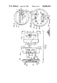
- FIG. 3 is a section view, taken across the lines 3--3 of FIG. 2, showing the disc mounted on the rotating shaft forwardly of the unit decade dial on the meter, and further showing (one of) the inductors on a printed circuit board mounted on the lower portion of the front panel for the meter.
- FIG. 4 is a front elevation of the disc and the inductors, the intermediate inductor being common to the other two and forming therebetween two pairs of inductors, and the broken radial lines on the disc illustrating (schematically) the location of the five spaced-apart apertures formed on the annular rim on the disc.
- FIG. 5 is a section view, taken across the lines 5--5 of FIG. 4, showing the disc formed from a dielectric material, the annular metallic rim thereon, and one of the inductors radially of the rim and fixedly mounted on the printed circuit board.
- FIG. 6 is a view, taken along the lines 6--6 of FIG. 4, showing the plan outline of one of the apertures in the rim.
- FIG. 7 is a schematic diagram of the preferred electronic circuitry on the p.c. board, the broken lines illustrating the inductive coupling between respective first and second inductors and a third common inductor, whenever a respective inductor is energized, and whenever a respective aperture on the rim substantially bridges the respective energized inductor with the third common inductor.
- FIG. 8 is an exploded cut-away view illustrating the implementation of the present invention to a two-piece adapter presently used for special conversions involving other metering problems.
- FIG. 9 is a view taken along the lines 9--9 of FIG. 8, showing the respective inductors on a board mounted on the meter.
- FIG. 10 is a view taken along the lines 10--10 of FIG. 8, showing the p.c. board mounted between the base and the collar portions of the adapter.
- a preferred embodiment 10 of the pick-up means of the present invention comprises a disc 11 having a metallic annular rim 12 mounted on its circumference.
- the disc is made from a suitable insulating or dielectric material, such as molded plastic, and the rim may be made from a thin copper sheet rolled into an annular shape and adhesively secured to the disc.
- the disc is press-fitted or otherwise suitably mounted on a shaft 13 for conjoint rotation therewith.
- the shaft is journaled between the back panel 14 and the top front panel 15 of the meter 16, as shown in FIG. 3, and the disc is disposed forwardly of the top front panel.
- a pinion gear 17 is carried by the shaft for cooperation with a spur gear 18.
- This spur gear is part of a gear train within the meter; this gear train is conventional, however, and hence has been omitted for ease of illustration.
- a plurality of coils or inductors 19, 20 and 21 are fixedly mounted on a plate (or board) 22 radially of the rim.
- Inductors 19 and 21 comprise first and second inductors, respectively, and inductor 20 therebetween is a third or common inductor.
- a plurality of spaced-apart arcuately-formed apertures 23 are formed on the rim for cooperation with the respective pairs of inductors.
- each aperture 23 comprises a round opening or hole 24 joined by a slot 25.
- Means are provided, as hereinafter described, for sequentially energizing one of the inductors 19 and 21; and at a predetermined circumferential position of the disc, one of the apertures on the rim bridges inductors 19, 20 or 20, 21, thereby effecting an inductive coupling between the respective inductor pairs 19, 20 or 20,21, and thereby generating a signal in the third common inductor 20.
- Means are further provided, as hereinafter described, for amplifying and shaping the signal to produce a pulse, and the pulses are registered on a remote means, thereby monitoring the position of the disc and the shaft on which the disc is mounted.
- the meter 16 is a standard service electric meter (for use in households as well as in commercial and industrial establishments) and has a plurality of decade dials 26, including a unit decade dial 27, on its top front panel 15.
- the disc 12 is mounted forwardly of the unit decade dial and is substantially alined (coaxially) therewith, as shown more clearly in FIG. 2.
- a pointer 28 is carried on the face of the disc; this pointer may simply be painted on the disc, if desired.
- the inductors are mounted on a plate which, as shown more clearly in FIG. 4, has a concave surface 29 complementary to the circumference of the disc and spaced closely thereto.
- the respective axes of the three inductors are disposed substantially radially of the disc, and the inner end portions of the inductors are substantially alined, circumferentially, with respect to one another and are disposed closely to the rim on the rotating disc.
- the plate 22 (on which the three inductors are mounted) constitutes an integral upper projecting portion of a printed circuit board (or "p.c.”board) 30.
- This p.c. board is mounted by suitable means (including a "stand-off” 31) to the back of the bottom front panel 32 of the meter.
- the p.c. board carries a transformer 33 (and electronic circuit means, as hereinafter described).
- a pair of wires 34 (or other suitable conductors) connect the output of the circuit means on the p.c. board to a remote register or other remote monitoring means.
- this remote register comprises a digital read-out counter 35.
- This counter may be mounted on the outside of the building (not shown) to facilitate a remote reading of the meter.
- the wires may extend for up to two hundred (200) feet.
- the electronic circuit means is quite similar to that which is illustrated and claimed in the aforesaid copending application, and thus will be described generally herein.
- the inductive coupling between the respective inductor pairs 19, 20 and 20, 21-- which is due to the sequential energization of one of the inductors (19 or 21) and the substantially simultaneous bridging of a respective inductor pair by one of the apertures 23, at a predetermined circumferential position of the disc 12--is illustrated by the broken lines 36 and 37, respectively.
- Each of the inductors 19, 20 and 21 is provided with a resonating capacitor 38, 39 and 40, respectively.
- the inductor pairs 19, 20 and 20, 21, respectively, are sequentially energized by oscillator drive switches, comprising respective switching transistors 41 and 42 controlled by a bi-stable flip-flop 43 through respective resistors 44 and 45.
- the signal from the common inductor 20 constitutes a pulse fed via resistor 46 and capacitor 47 to the base 48 of a transistor oscillator 49.
- the collector 50 of transistor 49 is connected via a diode 51 to a detector network which comprises a diode 52, resistors 53 and 54, and capacitor 55.
- the detector is connected to an operational amplifier 56 and thence to a Schmitt trigger 57, the output of which is connected via a capacitor 58 to trigger a "one-shot" integrated circuit 59.
- the output of this "I.C.” 59 is fed to the base 60 of a transistor driver 61, the emitter output of which provides a suitably shaped and amplified pulse. This pulse is registered (or “counted") by the remote digital read-out counter 25 or other suitable means.
- the power supply includes the transformer 33 and a full-wave rectifier bridge 62.
- the adapter which is widely used, includes a base member 63 and a collar member 64.
- these members are annular and are molded from a suitable material having relatively-high strength and good electrical insulating qualities.
- the collar is seated on the base; and if desired, the complementary circumferential edges therebetween may be joined by a suitable composition, such as a room-temperature vulcanizable ("RTV") material (not shown) for sealing purposes.
- Terminals 65 are mounted in the bottom plate 66 of the collar; these terminals have male prongs 67 and female receptacles 68.
- the male prongs extend through slots 69 in the base member 63 for plugging into an existing (older) meter installation (not shown).
- the new meter 70 to be installed (which is substantially similar to the meter 16 shown in FIG. 2) has prongs 71 received within the receptacles 68 on the adapter terminals. A total of four terminals may be provided, as shown more clearly in FIG. 10. With this arrangement, the "old" meter (not shown) may be removed from an existing meter installation; the adapter may be plugged into the existing installation; and the "new" meter 70 may be plugged into the adapter.
- the particular adapter shown herein is manufactured and sold by Ekstrom Industries, Inc. (as model no. 37-4JHRG3). However, it will be appreciated by those skilled in the art that the present invention is not restricted to the particular adapter shown herein, but is equally applicable to a wide variety of adapters.
- the plate (on which the inductors 19-21 are mounted) is not formed integrally with the p.c. board 30 (as in the embodiment of FIGS. 1-6) but rather is a separate plate (or board) 22', as shown more clearly in FIG. 9.
- the plate 22' is adhesively secured in place.
- the inductors 19-21 on plate 22' are connected by a flexible ribbon cable 72 carrying a female-type of plug 73 on its end. This plug is connected to a male-type of receptacle 74, which preferably has five prongs 75 (as shown more clearly in FIG. 10).
- the prongs in the receptacle are accessible via a rectangular opening 76 formed in the bottom 66 of the collar member; and the plug 73 on the end of the ribbon cable 72 may be plugged into the receptacle 74, prior to plugging the meter into the adapter.
- the receptacle is mounted on a p.c. board 30', which is similar to the p.c. board 30 of the embodiment shown in FIGS. 1-6. This p.c. board 30' is mounted on the base member 63 (as shown in FIG. 8).
- the transformer 33 extends through a clearance opening 77 and into the bottom 66 of the collar 64 (without interfering with the meter 70).
Abstract
Description
Claims (8)
Priority Applications (1)
| Application Number | Priority Date | Filing Date | Title |
|---|---|---|---|
| US06/439,921 US4608564A (en) | 1982-11-08 | 1982-11-08 | Apparatus for the remote monitoring of meters and other devices |
Applications Claiming Priority (1)
| Application Number | Priority Date | Filing Date | Title |
|---|---|---|---|
| US06/439,921 US4608564A (en) | 1982-11-08 | 1982-11-08 | Apparatus for the remote monitoring of meters and other devices |
Publications (1)
| Publication Number | Publication Date |
|---|---|
| US4608564A true US4608564A (en) | 1986-08-26 |
Family
ID=23746694
Family Applications (1)
| Application Number | Title | Priority Date | Filing Date |
|---|---|---|---|
| US06/439,921 Expired - Fee Related US4608564A (en) | 1982-11-08 | 1982-11-08 | Apparatus for the remote monitoring of meters and other devices |
Country Status (1)
| Country | Link |
|---|---|
| US (1) | US4608564A (en) |
Cited By (5)
| Publication number | Priority date | Publication date | Assignee | Title |
|---|---|---|---|---|
| US5451939A (en) * | 1990-08-20 | 1995-09-19 | Fisher-Rosemount Limited | Microprocessor controlled transmitter for connection to a sensor and a method of transferring digital signals to the microprocessor |
| US5621316A (en) * | 1991-01-04 | 1997-04-15 | Scientific Generics Limited | Apparatus for measuring the positions of plural movable members each associated with a respective magnetorestrictive element |
| WO2000058738A1 (en) * | 1999-03-30 | 2000-10-05 | Infra-Read, Llc | Utility meter reading device and related method |
| US6667612B2 (en) * | 2000-07-31 | 2003-12-23 | Commissariat A L'energie Atomique | Short-distance locating system |
| WO2011128698A1 (en) * | 2010-04-15 | 2011-10-20 | And Technology Research Limited | An electromagnetic method for sensing the relative position of two items using coupled tuned circuits |
Citations (10)
| Publication number | Priority date | Publication date | Assignee | Title |
|---|---|---|---|---|
| US2403889A (en) * | 1943-08-24 | 1946-07-09 | Hazeltine Research Inc | Telemetering system |
| US2403890A (en) * | 1943-08-24 | 1946-07-09 | Hazeltine Research Inc | Telemetering system |
| DE1163200B (en) * | 1961-04-05 | 1964-02-13 | Licentia Gmbh | Control organ for influencing high-frequency fields |
| US3176241A (en) * | 1961-04-07 | 1965-03-30 | Jimmie S Hogan | Magnetic switching device |
| US3656112A (en) * | 1969-03-14 | 1972-04-11 | Constellation Science And Tech | Utility meter remote automatic reading system |
| US3750122A (en) * | 1971-04-19 | 1973-07-31 | Mitsubishi Electric Corp | Induction type telemetering system |
| US4032906A (en) * | 1975-07-21 | 1977-06-28 | Jackson Jr Lewis B | Condition sampling and indicating system |
| US4121147A (en) * | 1975-01-02 | 1978-10-17 | Sangamo Electric Company | Electric meter for mounting with a standard watthour meter |
| US4296411A (en) * | 1978-09-25 | 1981-10-20 | Pat Romanelli | Electronic remote meter reading apparatus |
| US4491789A (en) * | 1981-08-14 | 1985-01-01 | Westinghouse Electric Corp. | Electrical energy meter having a cover-mounted time-of-day multifunction register |
-
1982
- 1982-11-08 US US06/439,921 patent/US4608564A/en not_active Expired - Fee Related
Patent Citations (10)
| Publication number | Priority date | Publication date | Assignee | Title |
|---|---|---|---|---|
| US2403889A (en) * | 1943-08-24 | 1946-07-09 | Hazeltine Research Inc | Telemetering system |
| US2403890A (en) * | 1943-08-24 | 1946-07-09 | Hazeltine Research Inc | Telemetering system |
| DE1163200B (en) * | 1961-04-05 | 1964-02-13 | Licentia Gmbh | Control organ for influencing high-frequency fields |
| US3176241A (en) * | 1961-04-07 | 1965-03-30 | Jimmie S Hogan | Magnetic switching device |
| US3656112A (en) * | 1969-03-14 | 1972-04-11 | Constellation Science And Tech | Utility meter remote automatic reading system |
| US3750122A (en) * | 1971-04-19 | 1973-07-31 | Mitsubishi Electric Corp | Induction type telemetering system |
| US4121147A (en) * | 1975-01-02 | 1978-10-17 | Sangamo Electric Company | Electric meter for mounting with a standard watthour meter |
| US4032906A (en) * | 1975-07-21 | 1977-06-28 | Jackson Jr Lewis B | Condition sampling and indicating system |
| US4296411A (en) * | 1978-09-25 | 1981-10-20 | Pat Romanelli | Electronic remote meter reading apparatus |
| US4491789A (en) * | 1981-08-14 | 1985-01-01 | Westinghouse Electric Corp. | Electrical energy meter having a cover-mounted time-of-day multifunction register |
Cited By (8)
| Publication number | Priority date | Publication date | Assignee | Title |
|---|---|---|---|---|
| US5451939A (en) * | 1990-08-20 | 1995-09-19 | Fisher-Rosemount Limited | Microprocessor controlled transmitter for connection to a sensor and a method of transferring digital signals to the microprocessor |
| US5621316A (en) * | 1991-01-04 | 1997-04-15 | Scientific Generics Limited | Apparatus for measuring the positions of plural movable members each associated with a respective magnetorestrictive element |
| WO2000058738A1 (en) * | 1999-03-30 | 2000-10-05 | Infra-Read, Llc | Utility meter reading device and related method |
| US6667612B2 (en) * | 2000-07-31 | 2003-12-23 | Commissariat A L'energie Atomique | Short-distance locating system |
| WO2011128698A1 (en) * | 2010-04-15 | 2011-10-20 | And Technology Research Limited | An electromagnetic method for sensing the relative position of two items using coupled tuned circuits |
| CN102939516A (en) * | 2010-04-15 | 2013-02-20 | 安徳科技研究有限公司 | Electromagnetic method for sensing relative position between two objects by using coupling tuning circuit |
| GB2482651B (en) * | 2010-04-15 | 2013-05-01 | And Technology Res Ltd | An electromagnetic method for sensing the relative position of two items using coupled tuned circuits |
| CN102939516B (en) * | 2010-04-15 | 2016-03-02 | 安徳科技研究有限公司 | Electromagnetic method for sensing relative position between two objects by using coupling tuning circuit |
Similar Documents
| Publication | Publication Date | Title |
|---|---|---|
| US4463354A (en) | Apparatus for communicating utility usage related information from a utility usage location to a portable utility usage registering device | |
| US4608564A (en) | Apparatus for the remote monitoring of meters and other devices | |
| GB2178928A (en) | Meter reader | |
| EP0047463A1 (en) | Electric micrometer | |
| US3943498A (en) | Direct input photoelectric pulse initiator for meter telemetry and recording systems | |
| US10241142B2 (en) | Systems and methods for locating a circuit | |
| US4264897A (en) | Meter register encoder including electronics providing remote reading capability | |
| US3706086A (en) | Solid state scanner for a remote meter reading system | |
| US3299627A (en) | Elapsed time meter | |
| EP0104748B1 (en) | Rf watt meter | |
| CN101901679B (en) | Concentricity-autocompensation type coaxial capacitance partial pressure electronic voltage transformer and compensation method thereof | |
| US2715723A (en) | Vehicle speedometer having electrical alarm system | |
| US4030014A (en) | Current-to-current electrical isolator | |
| GB1441847A (en) | Electricity meter or electrically operated counter with switch means which are reversible through an audio-frequency powerline control receiver | |
| US3044046A (en) | Telemetering system | |
| US2319432A (en) | Meter construction | |
| ATE33522T1 (en) | DEVICE FOR MEASURING TORQUE OR TORSION ANGLE. | |
| US2852741A (en) | Directional wattmeter | |
| US3449736A (en) | Meter reading system | |
| SU1698800A1 (en) | Non-contact current loadings level indicator | |
| SU540153A1 (en) | Device for calibration of flow meters | |
| JPS6318196Y2 (en) | ||
| JPS6117632Y2 (en) | ||
| CN2199565Y (en) | Mechanical counter | |
| JPS58212295A (en) | Transmitter of contactless signal |
Legal Events
| Date | Code | Title | Description |
|---|---|---|---|
| AS | Assignment |
Owner name: GENERAL SERVICES ENGINEERING, INC. 1965 GREENSPRIN Free format text: ASSIGNMENT OF ASSIGNORS INTEREST.;ASSIGNOR:HOFFMAN, GARY R.;REEL/FRAME:004067/0493 Effective date: 19821105 |
|
| REMI | Maintenance fee reminder mailed | ||
| AS | Assignment |
Owner name: CHEMICAL BANK, A NY BANKING CORPORATION Free format text: SECURITY INTEREST;ASSIGNORS:EXIDE CORPORATION;GENERAL BATTERY CORPORATION;ESB PUERTO RICO CORP.;AND OTHERS;REEL/FRAME:005449/0001 Effective date: 19900831 |
|
| LAPS | Lapse for failure to pay maintenance fees | ||
| STCH | Information on status: patent discontinuation |
Free format text: PATENT EXPIRED DUE TO NONPAYMENT OF MAINTENANCE FEES UNDER 37 CFR 1.362 |
|
| FP | Lapsed due to failure to pay maintenance fee |
Effective date: 19900826 |
|
| AS | Assignment |
Owner name: CREDIT SUISSE FIRST BOSTON, AS ADMINISTRATIVE AGEN Free format text: AMENDED AND RESTATED PATENT SECURITY AGREEMENT;ASSIGNOR:EXIDE CORPORATION;REEL/FRAME:011204/0600 Effective date: 20000928 |