US4614390A - Lead sealing assembly - Google Patents
Lead sealing assembly Download PDFInfo
- Publication number
- US4614390A US4614390A US06/735,427 US73542785A US4614390A US 4614390 A US4614390 A US 4614390A US 73542785 A US73542785 A US 73542785A US 4614390 A US4614390 A US 4614390A
- Authority
- US
- United States
- Prior art keywords
- cap
- housing
- sealing member
- lead
- cavity
- Prior art date
- Legal status (The legal status is an assumption and is not a legal conclusion. Google has not performed a legal analysis and makes no representation as to the accuracy of the status listed.)
- Expired - Lifetime
Links
Images


Classifications
-
- H—ELECTRICITY
- H01—ELECTRIC ELEMENTS
- H01R—ELECTRICALLY-CONDUCTIVE CONNECTIONS; STRUCTURAL ASSOCIATIONS OF A PLURALITY OF MUTUALLY-INSULATED ELECTRICAL CONNECTING ELEMENTS; COUPLING DEVICES; CURRENT COLLECTORS
- H01R13/00—Details of coupling devices of the kinds covered by groups H01R12/70 or H01R24/00 - H01R33/00
- H01R13/46—Bases; Cases
- H01R13/52—Dustproof, splashproof, drip-proof, waterproof, or flameproof cases
- H01R13/5205—Sealing means between cable and housing, e.g. grommet
-
- H—ELECTRICITY
- H01—ELECTRIC ELEMENTS
- H01R—ELECTRICALLY-CONDUCTIVE CONNECTIONS; STRUCTURAL ASSOCIATIONS OF A PLURALITY OF MUTUALLY-INSULATED ELECTRICAL CONNECTING ELEMENTS; COUPLING DEVICES; CURRENT COLLECTORS
- H01R13/00—Details of coupling devices of the kinds covered by groups H01R12/70 or H01R24/00 - H01R33/00
- H01R13/46—Bases; Cases
- H01R13/52—Dustproof, splashproof, drip-proof, waterproof, or flameproof cases
-
- H—ELECTRICITY
- H01—ELECTRIC ELEMENTS
- H01R—ELECTRICALLY-CONDUCTIVE CONNECTIONS; STRUCTURAL ASSOCIATIONS OF A PLURALITY OF MUTUALLY-INSULATED ELECTRICAL CONNECTING ELEMENTS; COUPLING DEVICES; CURRENT COLLECTORS
- H01R13/00—Details of coupling devices of the kinds covered by groups H01R12/70 or H01R24/00 - H01R33/00
- H01R13/58—Means for relieving strain on wire connection, e.g. cord grip, for avoiding loosening of connections between wires and terminals within a coupling device terminating a cable
Definitions
- This invention relates to a lead sealing assembly, particularly, but not exclusively, for sealing a housing containing an electrical terminal connected to an electrical lead and providing a seal between the lead and the housing.
- bung seals are commonly used for preventing the ingress of moisture between the housing of an electrical connector and a lead extending therefrom, the loading of the housing with a terminal connected to a lead is complicated by the necessity for threading the lead through the bung seal before connecting the terminal to the lead end, unless a specialized tool is employed, and the threading operation is in any event difficult to carry out rapidly because unless the bung seal offers substantial resistance to the treading of the lead therethrough, effective sealing between the lead and the housing is unlikely to be achieved.
- an electrical lead sealing assembly comprising a housing for receiving an electrical lead, an elastomeric, annular sealing member in the housing, and through which the lead can freely be passed, and an annular cap through which the lead can also freely be passed.
- the cap can be moved from an outer position in the housing into a home position in the housing axially to compress the sealing member.
- the sealing member is recessed so that when it is compressed by the cap it is thereby collapsed so as to form a seal between the lead and the housing.
- Means are provided for retaining the cap in its home position.
- the assembly may be used simply for providing a seal about a lead, or the sealing member may be dimensioned not only freely to receive a lead, but also freely to receive a terminal connected to the lead, whereby the housing can be loaded, without the use of tooling, with a terminal which has been applied to the lead by means of an automatic machine for cutting lead lengths from a continuous supply of wire and applying terminals to the ends of such lead lengths.
- the sealing member is preferably of circular cross-section, having a substantially V-shaped recess extending about the entire circumference of the sealing member, centrally thereof.
- the depth of the recess is preferably such that the wall of the sealing member, at the base of the recess, is as thin as possible, being, for example, in the form of a membrane connecting two major portions of the sealing member.
- the cap is preferably arranged to be releasably retained in its outer position in the cavity in which it does not compress the seal, being drivable from such position into its home position.
- the housing, the sealing member, and the cap may thus form a single unit whereby all that needs to be done to complete the sealed connector is to insert the terminal into the cavity and then to drive home the cap.
- FIG. 1 is an exploded perspective view of an electrical lead sealing assembly in association with an electrical terminal that has been crimped to an end of lead, the assembly comprising an insulating housing, a sealing member, and a cap;
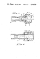
- FIG. 2 is an axial sectional view of the assembly
- FIG. 3 is a similar view to that of FIG. 2 but showing the cap when it has been driven to a home position in the housing to compress the sealing member;
- FIG. 4 is a similar view to that of FIG. 2 but showing the terminal after its insertion into the housing;
- FIG. 5 is a similar view to that of FIG. 4 but showing the assembly when the cap has been driven home to provide a seal between the lead and the housing;
- FIG. 6 is a similar view to that of FIG. 2 but illustrating a modification of the assembly.
- the assembly comprises a circular cross section insulating housing 2, and elastomeric, annular sealing member in the form of a sealing ring 4, which is also of circular cross section, and a circular cross-section, annular cap 5.
- the cap may be of the same material as the housing, or may be of metal.
- the sealing ring 5 is made of an elastomeric material. Both the sealing ring 4 and the cap 5 may be made of a synthetic rubber-like material, but the flexibility of the cap 5 must be substantially less than that of the sealing ring 4.
- the housing 2 defines a circular cross-section cavity 6 having a first portion 8, and a second portion 10 of substantially greater cross-sectional area than the portion 8.
- the housing 2 defines, in the portion 8, a first annular shoulder 12, and a second annular shoulder 14 extending normally of the shoulder 12. Between the shoulder 14 and the right hand (as seen in FIGS. 2 to 5) end 15 of the housing, the housing has a cylindrical wall 16 formed with windows 18 and 20, the windows 18 which are all on the same circumference are proximate to the shoulder 14, the windows 20 which are also all on the same circumference being proximate to the end 15 of the housing 2.
- a latching shoulder 24 is provided in the portion 8 of the cavity 6, towards the left hand (as seen in FIGS. 2 to 5) end 25 of the housing 2.
- the sealing ring 4 which is substantially dumbbell shaped as shown in FIG. 1, has an external peripheral recess in the form of a circumferential groove 26 which, as seen in FIGS. 2 and 4 is of substantially V-shaped cross section, being axially central of the ring 4.
- the depth of the groove 26 is such that the wall of the ring 4, at the base of the groove 26 is very thin, being in the form of a membrane 28 connecting two major portions 30 and 32 of the ring 4.
- the ring 4 has a circular cross-section bore 34 of constant cross-sectional area.
- the cap 5 is of overall circular cylindrical shape is dimensioned so as to be slidable in the cavity portion 10, along the internal wall of the portion 16 of the housing 2. There are formed on the external cylindrical surface of the cap 5, detents in the form of lugs 36, which lie on the same circumference in the vicinity of the left hand (as seen in the drawings) end of the cap 5.
- the cap 5 is formed with a skirt 38 defining an annular shoulder 40 and has a circular cross-section bore 42, of constant cross-sectional area.
- the assembly described above is intended to be loaded with an electrical terminal T which has been crimped to the end of an insulated lead L.
- the bores 34 and 42 of the ring 4 and of the cap 5, respectively, are both dimensioned so that their cross-sectional areas substantially exceed the maximum cross sectional area of the terminal T and the lead L, to an extent to allow both of these freely to be passed through the bores 34 and 42.
- the ring 4 is accommodated in the portion 10 of the cavity 6 with its major portion 30 abutting the shoulders 12 and 14.
- the cap 5 is shown in FIGS. 2 and 4 in a first, outer, position in which it is captive in the portion 10 of the cavity 6 by virtue of the engagement of the lugs 36 in the windows 20 of the wall 16.
- the lugs 36 are in the form of barbs which prevent retractile movement of the cap 5 from its said outer position, but allow it to be advanced into the portion 10 of the cavity 6 into a second, home, position (FIG. 3) in which the lugs 36 engage in the windows 18 so that the cap 5 is retained in its home position.
- the cap 5 engages the sealing ring 40 as shown in FIG. 3, so that the major portions 30 and 32 thereof are forced together by compression between the shoulder 40 of the cap 5 and the shoulder 12 of the housing 2, causing the ring 4 to be deformed radially inwardly of the cavity portion 10, the engagement of the lugs 36 in the windows 18 preventing any retractile movement of the cap 5 so that it is secured in its home position.
- the terminal T In order to load the assembly with the terminal T on the lead L, the terminal T is passed freely through the bores 42 and 34 until a locking tongue LT on the terminal T snaps behind the shoulder 24, thereby preventing retraction of the terminal T from the cavity 6. In this position of the terminal T, the lead L extends from the terminal T through both of the bores 34 and 42 and out of the assembly.
- the cap 5 When the cap 5 is now driven from its outer, to its home, position (FIG. 5) the ring 4 is compressed between the shoulders 12 and 40 as described above with reference to FIG. 3 and is thereby caused to expand radially so as to form a tight seal between the lead L and the housing 2, the shoulder 40 exerting a continuous and permanent compressive force against the seal 4, since the cap 5 cannot be retracted from its second position.
- the sealing ring may be formed integrally with the housing, or may be a separate part which is dropped into the cavity in the housing.
- the assembly may be as shown in FIG. 5 in which the sealing ring 4 has chamfered axially outer end faces 50 and 52, which cooperate with complementary inclined faces 54 and 56, of the housing 2' and of the cap 5', respectively, for locating ring 4' in the cavity portion 10'.
- the cap may be provided with conventional latching arms (not shown) which extend externally of the housing for engagement with complementary recesses therein, instead of being provided with the lugs 36.
- the sealing means described above require no lubrication.
- sealing means described above could be applied to a multiway electrical connector.
Abstract
Description
Claims (5)
Applications Claiming Priority (2)
| Application Number | Priority Date | Filing Date | Title |
|---|---|---|---|
| GB848431301A GB8431301D0 (en) | 1984-12-12 | 1984-12-12 | Lead sealing assembly |
| GB8431301 | 1984-12-12 |
Publications (1)
| Publication Number | Publication Date |
|---|---|
| US4614390A true US4614390A (en) | 1986-09-30 |
Family
ID=10571044
Family Applications (1)
| Application Number | Title | Priority Date | Filing Date |
|---|---|---|---|
| US06/735,427 Expired - Lifetime US4614390A (en) | 1984-12-12 | 1985-05-17 | Lead sealing assembly |
Country Status (2)
| Country | Link |
|---|---|
| US (1) | US4614390A (en) |
| GB (2) | GB8431301D0 (en) |
Cited By (118)
| Publication number | Priority date | Publication date | Assignee | Title |
|---|---|---|---|---|
| US4758182A (en) * | 1986-10-16 | 1988-07-19 | Shinagawa Jidosha Densen Co. Ltd. | Electric connector |
| US4802867A (en) * | 1986-12-05 | 1989-02-07 | Amp Incorporated | Electrical connector housing assembly |
| US4810208A (en) * | 1987-05-22 | 1989-03-07 | Amp Incorporated | Probeable sealed connector |
| US4820181A (en) * | 1987-04-13 | 1989-04-11 | Yazaki Corporation | Watertight connector |
| US4902247A (en) * | 1987-06-16 | 1990-02-20 | Sumitomo Wiring Systems | Electrical connector |
| US4921448A (en) * | 1988-05-06 | 1990-05-01 | Yazaki Corporation | Connector terminal retainer construction |
| US4973266A (en) * | 1988-08-09 | 1990-11-27 | Dill Products Incorporated | Combined terminal secondary lock and seal |
| US5052699A (en) * | 1989-07-10 | 1991-10-01 | Raychem Corporation | Grommet |
| US5082453A (en) * | 1991-05-16 | 1992-01-21 | Siemens-Pacesetter, Inc. | Multi-contact connector system for an implantable medical device |
| US5470257A (en) * | 1994-09-12 | 1995-11-28 | John Mezzalingua Assoc. Inc. | Radial compression type coaxial cable end connector |
| US5571028A (en) * | 1995-08-25 | 1996-11-05 | John Mezzalingua Assoc., Inc. | Coaxial cable end connector with integral moisture seal |
| US5613868A (en) * | 1994-05-23 | 1997-03-25 | Yazaki Corporation | Waterproof connector |
| US5634808A (en) * | 1994-08-30 | 1997-06-03 | Yazaki Corporation | Waterproof packing for connectors |
| US5679019A (en) * | 1994-02-25 | 1997-10-21 | Yazaki Corporation | Waterproof tap cover for waterproof connector |
| US5951595A (en) * | 1996-05-13 | 1999-09-14 | Pacesetteer, Inc. | Setscrewless connector assembly for implantable medical devices |
| US6045403A (en) * | 1996-08-01 | 2000-04-04 | Robert Bosch Gmbh | Line connector between two electric lines |
| US6089912A (en) * | 1996-10-23 | 2000-07-18 | Thomas & Betts International, Inc. | Post-less coaxial cable connector |
| US6153830A (en) * | 1997-08-02 | 2000-11-28 | John Mezzalingua Associates, Inc. | Connector and method of operation |
| EP1059697A2 (en) * | 1999-06-10 | 2000-12-13 | Yazaki Corporation | Waterproof connector |
| USD436076S1 (en) | 2000-04-28 | 2001-01-09 | John Mezzalingua Associates, Inc. | Open compression-type coaxial cable connector |
| USD437826S1 (en) | 2000-04-28 | 2001-02-20 | John Mezzalingua Associates, Inc. | Closed compression-type coaxial cable connector |
| USD440539S1 (en) | 1997-08-02 | 2001-04-17 | Noah P. Montena | Closed compression-type coaxial cable connector |
| US6331123B1 (en) | 2000-11-20 | 2001-12-18 | Thomas & Betts International, Inc. | Connector for hard-line coaxial cable |
| USD458904S1 (en) | 2001-10-10 | 2002-06-18 | John Mezzalingua Associates, Inc. | Co-axial cable connector |
| USD461166S1 (en) | 2001-09-28 | 2002-08-06 | John Mezzalingua Associates, Inc. | Co-axial cable connector |
| USD461778S1 (en) | 2001-09-28 | 2002-08-20 | John Mezzalingua Associates, Inc. | Co-axial cable connector |
| USD462058S1 (en) | 2001-09-28 | 2002-08-27 | John Mezzalingua Associates, Inc. | Co-axial cable connector |
| USD462327S1 (en) | 2001-09-28 | 2002-09-03 | John Mezzalingua Associates, Inc. | Co-axial cable connector |
| USD468696S1 (en) | 2001-09-28 | 2003-01-14 | John Mezzalingua Associates, Inc. | Co-axial cable connector |
| US6530807B2 (en) | 2000-05-10 | 2003-03-11 | Thomas & Betts International, Inc. | Coaxial connector having detachable locking sleeve |
| USD475975S1 (en) | 2001-10-17 | 2003-06-17 | John Mezzalingua Associates, Inc. | Co-axial cable connector |
| EP1070642A3 (en) * | 1999-07-22 | 2003-08-13 | REHAU AG + Co | Heating device for a windschield washer system |
| US20030224657A1 (en) * | 2002-05-31 | 2003-12-04 | Thomas & Betts International, Inc. | Connector for hard-line coaxial cable |
| US20040180575A1 (en) * | 2003-03-14 | 2004-09-16 | Thomas & Betts International, Inc. | Cable connector with universal locking sleeve |
| US6808415B1 (en) | 2004-01-26 | 2004-10-26 | John Mezzalingua Associates, Inc. | Clamping and sealing mechanism with multiple rings for cable connector |
| US20050136735A1 (en) * | 2003-12-17 | 2005-06-23 | Thomas & Betts International, Inc. | Coaxial connector having improved locking sleeve |
| US20050170692A1 (en) * | 2004-02-04 | 2005-08-04 | Noal Montena | Compression connector with integral coupler |
| US20050181652A1 (en) * | 2004-02-18 | 2005-08-18 | Noah Montena | Cable connector with elastomeric band |
| US7063565B2 (en) | 2004-05-14 | 2006-06-20 | Thomas & Betts International, Inc. | Coaxial cable connector |
| US7241172B2 (en) | 2004-04-16 | 2007-07-10 | Thomas & Betts International Inc. | Coaxial cable connector |
| US7288002B2 (en) | 2005-10-19 | 2007-10-30 | Thomas & Betts International, Inc. | Coaxial cable connector with self-gripping and self-sealing features |
| US7309255B2 (en) | 2005-03-11 | 2007-12-18 | Thomas & Betts International, Inc. | Coaxial connector with a cable gripping feature |
| US7329149B2 (en) | 2004-01-26 | 2008-02-12 | John Mezzalingua Associates, Inc. | Clamping and sealing mechanism with multiple rings for cable connector |
| US7347729B2 (en) | 2005-10-20 | 2008-03-25 | Thomas & Betts International, Inc. | Prepless coaxial cable connector |
| US7354307B2 (en) | 2005-06-27 | 2008-04-08 | Pro Brand International, Inc. | End connector for coaxial cable |
| US20080285243A1 (en) * | 2007-05-18 | 2008-11-20 | Fujitsu Limited | Storage apparatus and flexible printed board unit |
| US7455549B2 (en) | 2005-08-23 | 2008-11-25 | Thomas & Betts International, Inc. | Coaxial cable connector with friction-fit sleeve |
| US7566236B2 (en) | 2007-06-14 | 2009-07-28 | Thomas & Betts International, Inc. | Constant force coaxial cable connector |
| US7588460B2 (en) | 2007-04-17 | 2009-09-15 | Thomas & Betts International, Inc. | Coaxial cable connector with gripping ferrule |
| US20090280668A1 (en) * | 2008-05-08 | 2009-11-12 | Thomas & Betts International, Inc. | Connector with deformable Compression Sleeve |
| US7794275B2 (en) | 2007-05-01 | 2010-09-14 | Thomas & Betts International, Inc. | Coaxial cable connector with inner sleeve ring |
| US7828595B2 (en) | 2004-11-24 | 2010-11-09 | John Mezzalingua Associates, Inc. | Connector having conductive member and method of use thereof |
| US7892005B2 (en) | 2009-05-19 | 2011-02-22 | John Mezzalingua Associates, Inc. | Click-tight coaxial cable continuity connector |
| US7934954B1 (en) | 2010-04-02 | 2011-05-03 | John Mezzalingua Associates, Inc. | Coaxial cable compression connectors |
| US8029315B2 (en) | 2009-04-01 | 2011-10-04 | John Mezzalingua Associates, Inc. | Coaxial cable connector with improved physical and RF sealing |
| US8062063B2 (en) | 2008-09-30 | 2011-11-22 | Belden Inc. | Cable connector having a biasing element |
| US8075338B1 (en) | 2010-10-18 | 2011-12-13 | John Mezzalingua Associates, Inc. | Connector having a constant contact post |
| US8079860B1 (en) | 2010-07-22 | 2011-12-20 | John Mezzalingua Associates, Inc. | Cable connector having threaded locking collet and nut |
| US8113879B1 (en) | 2010-07-27 | 2012-02-14 | John Mezzalingua Associates, Inc. | One-piece compression connector body for coaxial cable connector |
| US8152551B2 (en) | 2010-07-22 | 2012-04-10 | John Mezzalingua Associates, Inc. | Port seizing cable connector nut and assembly |
| US8157589B2 (en) | 2004-11-24 | 2012-04-17 | John Mezzalingua Associates, Inc. | Connector having a conductively coated member and method of use thereof |
| US8167646B1 (en) | 2010-10-18 | 2012-05-01 | John Mezzalingua Associates, Inc. | Connector having electrical continuity about an inner dielectric and method of use thereof |
| US8167636B1 (en) | 2010-10-15 | 2012-05-01 | John Mezzalingua Associates, Inc. | Connector having a continuity member |
| US8167635B1 (en) | 2010-10-18 | 2012-05-01 | John Mezzalingua Associates, Inc. | Dielectric sealing member and method of use thereof |
| US8172612B2 (en) | 2005-01-25 | 2012-05-08 | Corning Gilbert Inc. | Electrical connector with grounding member |
| US8177582B2 (en) | 2010-04-02 | 2012-05-15 | John Mezzalingua Associates, Inc. | Impedance management in coaxial cable terminations |
| US8192237B2 (en) | 2009-05-22 | 2012-06-05 | John Mezzalingua Associates, Inc. | Coaxial cable connector having electrical continuity member |
| US8272893B2 (en) | 2009-11-16 | 2012-09-25 | Corning Gilbert Inc. | Integrally conductive and shielded coaxial cable connector |
| US8287310B2 (en) | 2009-02-24 | 2012-10-16 | Corning Gilbert Inc. | Coaxial connector with dual-grip nut |
| US8313345B2 (en) | 2009-04-02 | 2012-11-20 | John Mezzalingua Associates, Inc. | Coaxial cable continuity connector |
| US8323053B2 (en) | 2010-10-18 | 2012-12-04 | John Mezzalingua Associates, Inc. | Connector having a constant contact nut |
| EP2509167A3 (en) * | 2011-04-06 | 2012-12-19 | Robert Bosch GmbH | Connector with insertion aid for inserting contact elements |
| US8337229B2 (en) | 2010-11-11 | 2012-12-25 | John Mezzalingua Associates, Inc. | Connector having a nut-body continuity element and method of use thereof |
| US8342879B2 (en) | 2011-03-25 | 2013-01-01 | John Mezzalingua Associates, Inc. | Coaxial cable connector |
| US8348697B2 (en) | 2011-04-22 | 2013-01-08 | John Mezzalingua Associates, Inc. | Coaxial cable connector having slotted post member |
| US8366481B2 (en) | 2011-03-30 | 2013-02-05 | John Mezzalingua Associates, Inc. | Continuity maintaining biasing member |
| US8388377B2 (en) | 2011-04-01 | 2013-03-05 | John Mezzalingua Associates, Inc. | Slide actuated coaxial cable connector |
| US8398421B2 (en) | 2011-02-01 | 2013-03-19 | John Mezzalingua Associates, Inc. | Connector having a dielectric seal and method of use thereof |
| US8414322B2 (en) | 2010-12-14 | 2013-04-09 | Ppc Broadband, Inc. | Push-on CATV port terminator |
| US8444445B2 (en) | 2009-05-22 | 2013-05-21 | Ppc Broadband, Inc. | Coaxial cable connector having electrical continuity member |
| US8465322B2 (en) | 2011-03-25 | 2013-06-18 | Ppc Broadband, Inc. | Coaxial cable connector |
| US8468688B2 (en) | 2010-04-02 | 2013-06-25 | John Mezzalingua Associates, LLC | Coaxial cable preparation tools |
| US8469739B2 (en) | 2011-02-08 | 2013-06-25 | Belden Inc. | Cable connector with biasing element |
| US8556656B2 (en) | 2010-10-01 | 2013-10-15 | Belden, Inc. | Cable connector with sliding ring compression |
| DE102012206102A1 (en) * | 2012-04-13 | 2013-10-17 | Tyco Electronics Amp Gmbh | Electrical connector for connecting cable in motor vehicle, has spring element that is arranged to press cable against rib when seal holder is in final locking position |
| US8573996B2 (en) | 2009-05-22 | 2013-11-05 | Ppc Broadband, Inc. | Coaxial cable connector having electrical continuity member |
| US8591244B2 (en) | 2011-07-08 | 2013-11-26 | Ppc Broadband, Inc. | Cable connector |
| US8632360B2 (en) | 2011-04-25 | 2014-01-21 | Ppc Broadband, Inc. | Coaxial cable connector having a collapsible portion |
| US8753147B2 (en) | 2011-06-10 | 2014-06-17 | Ppc Broadband, Inc. | Connector having a coupling member for locking onto a port and maintaining electrical continuity |
| US8888526B2 (en) | 2010-08-10 | 2014-11-18 | Corning Gilbert, Inc. | Coaxial cable connector with radio frequency interference and grounding shield |
| US9017101B2 (en) | 2011-03-30 | 2015-04-28 | Ppc Broadband, Inc. | Continuity maintaining biasing member |
| US9048599B2 (en) | 2013-10-28 | 2015-06-02 | Corning Gilbert Inc. | Coaxial cable connector having a gripping member with a notch and disposed inside a shell |
| US9071019B2 (en) | 2010-10-27 | 2015-06-30 | Corning Gilbert, Inc. | Push-on cable connector with a coupler and retention and release mechanism |
| US9130281B2 (en) | 2013-04-17 | 2015-09-08 | Ppc Broadband, Inc. | Post assembly for coaxial cable connectors |
| US9136654B2 (en) | 2012-01-05 | 2015-09-15 | Corning Gilbert, Inc. | Quick mount connector for a coaxial cable |
| US9147955B2 (en) | 2011-11-02 | 2015-09-29 | Ppc Broadband, Inc. | Continuity providing port |
| US9147963B2 (en) | 2012-11-29 | 2015-09-29 | Corning Gilbert Inc. | Hardline coaxial connector with a locking ferrule |
| US9153911B2 (en) | 2013-02-19 | 2015-10-06 | Corning Gilbert Inc. | Coaxial cable continuity connector |
| US9166306B2 (en) | 2010-04-02 | 2015-10-20 | John Mezzalingua Associates, LLC | Method of terminating a coaxial cable |
| US9166348B2 (en) | 2010-04-13 | 2015-10-20 | Corning Gilbert Inc. | Coaxial connector with inhibited ingress and improved grounding |
| US9172154B2 (en) | 2013-03-15 | 2015-10-27 | Corning Gilbert Inc. | Coaxial cable connector with integral RFI protection |
| US9190744B2 (en) | 2011-09-14 | 2015-11-17 | Corning Optical Communications Rf Llc | Coaxial cable connector with radio frequency interference and grounding shield |
| US9203167B2 (en) | 2011-05-26 | 2015-12-01 | Ppc Broadband, Inc. | Coaxial cable connector with conductive seal |
| US9287659B2 (en) | 2012-10-16 | 2016-03-15 | Corning Optical Communications Rf Llc | Coaxial cable connector with integral RFI protection |
| US9407016B2 (en) | 2012-02-22 | 2016-08-02 | Corning Optical Communications Rf Llc | Coaxial cable connector with integral continuity contacting portion |
| US9525220B1 (en) | 2015-11-25 | 2016-12-20 | Corning Optical Communications LLC | Coaxial cable connector |
| US9548557B2 (en) | 2013-06-26 | 2017-01-17 | Corning Optical Communications LLC | Connector assemblies and methods of manufacture |
| US9548572B2 (en) | 2014-11-03 | 2017-01-17 | Corning Optical Communications LLC | Coaxial cable connector having a coupler and a post with a contacting portion and a shoulder |
| US9570845B2 (en) | 2009-05-22 | 2017-02-14 | Ppc Broadband, Inc. | Connector having a continuity member operable in a radial direction |
| US9590287B2 (en) | 2015-02-20 | 2017-03-07 | Corning Optical Communications Rf Llc | Surge protected coaxial termination |
| US9711917B2 (en) | 2011-05-26 | 2017-07-18 | Ppc Broadband, Inc. | Band spring continuity member for coaxial cable connector |
| US9762008B2 (en) | 2013-05-20 | 2017-09-12 | Corning Optical Communications Rf Llc | Coaxial cable connector with integral RFI protection |
| USD800072S1 (en) * | 2014-08-20 | 2017-10-17 | East Coast Innovations Pty. Ltd. | Electrical connector cover |
| US9859631B2 (en) | 2011-09-15 | 2018-01-02 | Corning Optical Communications Rf Llc | Coaxial cable connector with integral radio frequency interference and grounding shield |
| US10033122B2 (en) | 2015-02-20 | 2018-07-24 | Corning Optical Communications Rf Llc | Cable or conduit connector with jacket retention feature |
| DE102014108285B4 (en) | 2014-06-12 | 2018-09-20 | Lisa Dräxlmaier GmbH | Plug and mating connector |
| US10211547B2 (en) | 2015-09-03 | 2019-02-19 | Corning Optical Communications Rf Llc | Coaxial cable connector |
| US10290958B2 (en) | 2013-04-29 | 2019-05-14 | Corning Optical Communications Rf Llc | Coaxial cable connector with integral RFI protection and biasing ring |
Families Citing this family (14)
| Publication number | Priority date | Publication date | Assignee | Title |
|---|---|---|---|---|
| CA2080585C (en) * | 1991-02-15 | 2001-12-18 | Hugues Fortin | Electrical connector with sealing feed-through |
| FR2673049B1 (en) * | 1991-02-15 | 1994-12-02 | Fancelo | ELECTRICAL CONNECTOR WITH WATERPROOF WIRE THREAD. |
| US5208427A (en) * | 1992-01-31 | 1993-05-04 | Thomas & Betts Corporation | Connector for terminating electrical cable assemblies of multiple configurations |
| GB2284716B (en) * | 1993-11-03 | 1998-03-04 | Framatome Connectors Int | Improvements relating to cable sealing arrangements |
| JP3566540B2 (en) | 1998-03-31 | 2004-09-15 | 矢崎総業株式会社 | Waterproof connector |
| JP3566541B2 (en) * | 1998-03-31 | 2004-09-15 | 矢崎総業株式会社 | Waterproof connector and waterproofing method |
| JP3517109B2 (en) | 1998-03-31 | 2004-04-05 | 矢崎総業株式会社 | Waterproof connector and method of assembling waterproof connector |
| DE69939206D1 (en) * | 1998-06-08 | 2008-09-11 | Sumitomo Wiring Systems | WATERPROOF CONNECTOR |
| JPH11354201A (en) | 1998-06-10 | 1999-12-24 | Yazaki Corp | Waterproof connector |
| JP3500065B2 (en) | 1998-06-25 | 2004-02-23 | 矢崎総業株式会社 | Waterproof connector |
| JP3540164B2 (en) | 1998-07-06 | 2004-07-07 | 矢崎総業株式会社 | Waterproof connector |
| JP3691291B2 (en) * | 1999-06-28 | 2005-09-07 | 矢崎総業株式会社 | Waterproof connector |
| DE102010042341B3 (en) * | 2010-10-12 | 2012-04-05 | Intercontec Pfeiffer Gmbh | Plug part for an electrical connector and method for mounting a plug part |
| DE102017106597A1 (en) * | 2017-03-28 | 2018-10-04 | Rittal Gmbh & Co. Kg | Cable bushing for the introduction of a cable into a control cabinet, a corresponding control cabinet and a corresponding procedure |
Citations (4)
| Publication number | Priority date | Publication date | Assignee | Title |
|---|---|---|---|---|
| GB1051493A (en) * | 1900-01-01 | |||
| US3675184A (en) * | 1969-10-17 | 1972-07-04 | United Carr Inc | Combined cable clamp and seal for a backshell |
| US4114974A (en) * | 1977-08-29 | 1978-09-19 | General Electric Company | Dust shield for cap and connector |
| EP0033031A2 (en) * | 1979-12-26 | 1981-08-05 | AMP INCORPORATED (a New Jersey corporation) | Sealed electrical connector assembly |
Family Cites Families (4)
| Publication number | Priority date | Publication date | Assignee | Title |
|---|---|---|---|---|
| GB1037048A (en) * | 1963-10-19 | 1966-07-27 | Hawke Cable Glands Ltd | Improvements in or relating to electric cable glands |
| GB1281876A (en) * | 1968-09-24 | 1972-07-19 | Hawke Cable Glands Ltd | Improvements in or relating to electric cable glands |
| GB1361492A (en) * | 1972-04-12 | 1974-07-24 | Hawke Cable Glands Ltd | Electrical cable glands |
| GB1528348A (en) * | 1975-08-26 | 1978-10-11 | Hawke Cable Glands Ltd | Electric cable barrier |
-
1984
- 1984-12-12 GB GB848431301A patent/GB8431301D0/en active Pending
-
1985
- 1985-05-17 US US06/735,427 patent/US4614390A/en not_active Expired - Lifetime
- 1985-11-04 GB GB08527149A patent/GB2168548B/en not_active Expired
Patent Citations (4)
| Publication number | Priority date | Publication date | Assignee | Title |
|---|---|---|---|---|
| GB1051493A (en) * | 1900-01-01 | |||
| US3675184A (en) * | 1969-10-17 | 1972-07-04 | United Carr Inc | Combined cable clamp and seal for a backshell |
| US4114974A (en) * | 1977-08-29 | 1978-09-19 | General Electric Company | Dust shield for cap and connector |
| EP0033031A2 (en) * | 1979-12-26 | 1981-08-05 | AMP INCORPORATED (a New Jersey corporation) | Sealed electrical connector assembly |
Cited By (218)
| Publication number | Priority date | Publication date | Assignee | Title |
|---|---|---|---|---|
| US4758182A (en) * | 1986-10-16 | 1988-07-19 | Shinagawa Jidosha Densen Co. Ltd. | Electric connector |
| US4802867A (en) * | 1986-12-05 | 1989-02-07 | Amp Incorporated | Electrical connector housing assembly |
| US4820181A (en) * | 1987-04-13 | 1989-04-11 | Yazaki Corporation | Watertight connector |
| US4810208A (en) * | 1987-05-22 | 1989-03-07 | Amp Incorporated | Probeable sealed connector |
| US4902247A (en) * | 1987-06-16 | 1990-02-20 | Sumitomo Wiring Systems | Electrical connector |
| US4921448A (en) * | 1988-05-06 | 1990-05-01 | Yazaki Corporation | Connector terminal retainer construction |
| US4973266A (en) * | 1988-08-09 | 1990-11-27 | Dill Products Incorporated | Combined terminal secondary lock and seal |
| US5052699A (en) * | 1989-07-10 | 1991-10-01 | Raychem Corporation | Grommet |
| US5082453A (en) * | 1991-05-16 | 1992-01-21 | Siemens-Pacesetter, Inc. | Multi-contact connector system for an implantable medical device |
| US5679019A (en) * | 1994-02-25 | 1997-10-21 | Yazaki Corporation | Waterproof tap cover for waterproof connector |
| US5613868A (en) * | 1994-05-23 | 1997-03-25 | Yazaki Corporation | Waterproof connector |
| US5634808A (en) * | 1994-08-30 | 1997-06-03 | Yazaki Corporation | Waterproof packing for connectors |
| US5632651A (en) * | 1994-09-12 | 1997-05-27 | John Mezzalingua Assoc. Inc. | Radial compression type coaxial cable end connector |
| US5470257A (en) * | 1994-09-12 | 1995-11-28 | John Mezzalingua Assoc. Inc. | Radial compression type coaxial cable end connector |
| US5571028A (en) * | 1995-08-25 | 1996-11-05 | John Mezzalingua Assoc., Inc. | Coaxial cable end connector with integral moisture seal |
| US5951595A (en) * | 1996-05-13 | 1999-09-14 | Pacesetteer, Inc. | Setscrewless connector assembly for implantable medical devices |
| US6045403A (en) * | 1996-08-01 | 2000-04-04 | Robert Bosch Gmbh | Line connector between two electric lines |
| US6089912A (en) * | 1996-10-23 | 2000-07-18 | Thomas & Betts International, Inc. | Post-less coaxial cable connector |
| US6676446B2 (en) | 1997-08-02 | 2004-01-13 | John Mezzalingua Associates, Inc. | Connector and method of operation |
| US6848940B2 (en) | 1997-08-02 | 2005-02-01 | John Mezzalingua Associates, Inc. | Connector and method of operation |
| USD440539S1 (en) | 1997-08-02 | 2001-04-17 | Noah P. Montena | Closed compression-type coaxial cable connector |
| USD440939S1 (en) | 1997-08-02 | 2001-04-24 | Noah P. Montena | Open compression-type coaxial cable connector |
| US6558194B2 (en) | 1997-08-02 | 2003-05-06 | John Mezzalingua Associates, Inc. | Connector and method of operation |
| US6153830A (en) * | 1997-08-02 | 2000-11-28 | John Mezzalingua Associates, Inc. | Connector and method of operation |
| EP1059697A2 (en) * | 1999-06-10 | 2000-12-13 | Yazaki Corporation | Waterproof connector |
| EP1059697A3 (en) * | 1999-06-10 | 2001-08-29 | Yazaki Corporation | Waterproof connector |
| US6375500B1 (en) | 1999-06-10 | 2002-04-23 | Yazaki Corporation | Water proof connector having a seal confirmation access window |
| EP1070642A3 (en) * | 1999-07-22 | 2003-08-13 | REHAU AG + Co | Heating device for a windschield washer system |
| USD436076S1 (en) | 2000-04-28 | 2001-01-09 | John Mezzalingua Associates, Inc. | Open compression-type coaxial cable connector |
| USD437826S1 (en) | 2000-04-28 | 2001-02-20 | John Mezzalingua Associates, Inc. | Closed compression-type coaxial cable connector |
| US8449324B2 (en) | 2000-05-10 | 2013-05-28 | Belden Inc. | Coaxial connector having detachable locking sleeve |
| US8419470B2 (en) | 2000-05-10 | 2013-04-16 | Belden Inc. | Coaxial connector having detachable locking sleeve |
| US10411393B2 (en) | 2000-05-10 | 2019-09-10 | Ppc Broadband, Inc. | Coaxial connector having detachable locking sleeve |
| US6530807B2 (en) | 2000-05-10 | 2003-03-11 | Thomas & Betts International, Inc. | Coaxial connector having detachable locking sleeve |
| US7458849B2 (en) | 2000-05-10 | 2008-12-02 | Thomas & Betts International, Inc. | Coaxial connector having detachable locking sleeve |
| US9837752B2 (en) | 2000-05-10 | 2017-12-05 | Ppc Broadband, Inc. | Coaxial connector having detachable locking sleeve |
| US9385467B2 (en) | 2000-05-10 | 2016-07-05 | Ppc Broadband, Inc. | Coaxial connector having detachable locking sleeve |
| US6767247B2 (en) | 2000-05-10 | 2004-07-27 | Thomas & Betts International, Inc. | Coaxial connector having detachable locking sleeve |
| US8894440B2 (en) | 2000-05-10 | 2014-11-25 | Ppc Broadband, Inc. | Coaxial connector having detachable locking sleeve |
| US7192308B2 (en) | 2000-05-10 | 2007-03-20 | Thomas & Betts International, Inc. | Coaxial connector having detachable locking sleeve |
| US6331123B1 (en) | 2000-11-20 | 2001-12-18 | Thomas & Betts International, Inc. | Connector for hard-line coaxial cable |
| USD462327S1 (en) | 2001-09-28 | 2002-09-03 | John Mezzalingua Associates, Inc. | Co-axial cable connector |
| USD461166S1 (en) | 2001-09-28 | 2002-08-06 | John Mezzalingua Associates, Inc. | Co-axial cable connector |
| USD461778S1 (en) | 2001-09-28 | 2002-08-20 | John Mezzalingua Associates, Inc. | Co-axial cable connector |
| USD462058S1 (en) | 2001-09-28 | 2002-08-27 | John Mezzalingua Associates, Inc. | Co-axial cable connector |
| USD468696S1 (en) | 2001-09-28 | 2003-01-14 | John Mezzalingua Associates, Inc. | Co-axial cable connector |
| USD458904S1 (en) | 2001-10-10 | 2002-06-18 | John Mezzalingua Associates, Inc. | Co-axial cable connector |
| USD475975S1 (en) | 2001-10-17 | 2003-06-17 | John Mezzalingua Associates, Inc. | Co-axial cable connector |
| US6884115B2 (en) | 2002-05-31 | 2005-04-26 | Thomas & Betts International, Inc. | Connector for hard-line coaxial cable |
| US20030224657A1 (en) * | 2002-05-31 | 2003-12-04 | Thomas & Betts International, Inc. | Connector for hard-line coaxial cable |
| US20040180575A1 (en) * | 2003-03-14 | 2004-09-16 | Thomas & Betts International, Inc. | Cable connector with universal locking sleeve |
| US6817896B2 (en) | 2003-03-14 | 2004-11-16 | Thomas & Betts International, Inc. | Cable connector with universal locking sleeve |
| US20050136735A1 (en) * | 2003-12-17 | 2005-06-23 | Thomas & Betts International, Inc. | Coaxial connector having improved locking sleeve |
| US7473128B2 (en) | 2004-01-26 | 2009-01-06 | John Mezzalingua Associates, Inc. | Clamping and sealing mechanism with multiple rings for cable connector |
| US7329149B2 (en) | 2004-01-26 | 2008-02-12 | John Mezzalingua Associates, Inc. | Clamping and sealing mechanism with multiple rings for cable connector |
| US6808415B1 (en) | 2004-01-26 | 2004-10-26 | John Mezzalingua Associates, Inc. | Clamping and sealing mechanism with multiple rings for cable connector |
| US7163420B2 (en) | 2004-02-04 | 2007-01-16 | John Mezzalingua Assoicates, Inc. | Compression connector with integral coupler |
| US7029304B2 (en) | 2004-02-04 | 2006-04-18 | John Mezzalingua Associates, Inc. | Compression connector with integral coupler |
| US20050170692A1 (en) * | 2004-02-04 | 2005-08-04 | Noal Montena | Compression connector with integral coupler |
| US7118416B2 (en) | 2004-02-18 | 2006-10-10 | John Mezzalingua Associates, Inc. | Cable connector with elastomeric band |
| US20050181652A1 (en) * | 2004-02-18 | 2005-08-18 | Noah Montena | Cable connector with elastomeric band |
| US7241172B2 (en) | 2004-04-16 | 2007-07-10 | Thomas & Betts International Inc. | Coaxial cable connector |
| US7063565B2 (en) | 2004-05-14 | 2006-06-20 | Thomas & Betts International, Inc. | Coaxial cable connector |
| US10446983B2 (en) | 2004-11-24 | 2019-10-15 | Ppc Broadband, Inc. | Connector having a grounding member |
| US10965063B2 (en) | 2004-11-24 | 2021-03-30 | Ppc Broadband, Inc. | Connector having a grounding member |
| US10038284B2 (en) | 2004-11-24 | 2018-07-31 | Ppc Broadband, Inc. | Connector having a grounding member |
| US7828595B2 (en) | 2004-11-24 | 2010-11-09 | John Mezzalingua Associates, Inc. | Connector having conductive member and method of use thereof |
| US7833053B2 (en) | 2004-11-24 | 2010-11-16 | John Mezzalingua Associates, Inc. | Connector having conductive member and method of use thereof |
| US7845976B2 (en) | 2004-11-24 | 2010-12-07 | John Mezzalingua Associates, Inc. | Connector having conductive member and method of use thereof |
| US8157589B2 (en) | 2004-11-24 | 2012-04-17 | John Mezzalingua Associates, Inc. | Connector having a conductively coated member and method of use thereof |
| US9312611B2 (en) | 2004-11-24 | 2016-04-12 | Ppc Broadband, Inc. | Connector having a conductively coated member and method of use thereof |
| US7950958B2 (en) | 2004-11-24 | 2011-05-31 | John Messalingua Associates, Inc. | Connector having conductive member and method of use thereof |
| US10756455B2 (en) | 2005-01-25 | 2020-08-25 | Corning Optical Communications Rf Llc | Electrical connector with grounding member |
| US8172612B2 (en) | 2005-01-25 | 2012-05-08 | Corning Gilbert Inc. | Electrical connector with grounding member |
| US8690603B2 (en) | 2005-01-25 | 2014-04-08 | Corning Gilbert Inc. | Electrical connector with grounding member |
| US7309255B2 (en) | 2005-03-11 | 2007-12-18 | Thomas & Betts International, Inc. | Coaxial connector with a cable gripping feature |
| US7422479B2 (en) | 2005-06-27 | 2008-09-09 | Pro Band International, Inc. | End connector for coaxial cable |
| US7568945B2 (en) | 2005-06-27 | 2009-08-04 | Pro Band International, Inc. | End connector for coaxial cable |
| US7354307B2 (en) | 2005-06-27 | 2008-04-08 | Pro Brand International, Inc. | End connector for coaxial cable |
| US7887366B2 (en) | 2005-06-27 | 2011-02-15 | Pro Brand International, Inc. | End connector for coaxial cable |
| US7455549B2 (en) | 2005-08-23 | 2008-11-25 | Thomas & Betts International, Inc. | Coaxial cable connector with friction-fit sleeve |
| US7288002B2 (en) | 2005-10-19 | 2007-10-30 | Thomas & Betts International, Inc. | Coaxial cable connector with self-gripping and self-sealing features |
| US7347729B2 (en) | 2005-10-20 | 2008-03-25 | Thomas & Betts International, Inc. | Prepless coaxial cable connector |
| US7588460B2 (en) | 2007-04-17 | 2009-09-15 | Thomas & Betts International, Inc. | Coaxial cable connector with gripping ferrule |
| US7794275B2 (en) | 2007-05-01 | 2010-09-14 | Thomas & Betts International, Inc. | Coaxial cable connector with inner sleeve ring |
| US20080285243A1 (en) * | 2007-05-18 | 2008-11-20 | Fujitsu Limited | Storage apparatus and flexible printed board unit |
| US7566236B2 (en) | 2007-06-14 | 2009-07-28 | Thomas & Betts International, Inc. | Constant force coaxial cable connector |
| USRE43832E1 (en) | 2007-06-14 | 2012-11-27 | Belden Inc. | Constant force coaxial cable connector |
| US8491334B2 (en) | 2008-05-08 | 2013-07-23 | Belden Inc. | Connector with deformable compression sleeve |
| US20090280668A1 (en) * | 2008-05-08 | 2009-11-12 | Thomas & Betts International, Inc. | Connector with deformable Compression Sleeve |
| US8096830B2 (en) * | 2008-05-08 | 2012-01-17 | Belden Inc. | Connector with deformable compression sleeve |
| US8506325B2 (en) | 2008-09-30 | 2013-08-13 | Belden Inc. | Cable connector having a biasing element |
| US8062063B2 (en) | 2008-09-30 | 2011-11-22 | Belden Inc. | Cable connector having a biasing element |
| US8113875B2 (en) | 2008-09-30 | 2012-02-14 | Belden Inc. | Cable connector |
| US8075337B2 (en) | 2008-09-30 | 2011-12-13 | Belden Inc. | Cable connector |
| US8287310B2 (en) | 2009-02-24 | 2012-10-16 | Corning Gilbert Inc. | Coaxial connector with dual-grip nut |
| US8029315B2 (en) | 2009-04-01 | 2011-10-04 | John Mezzalingua Associates, Inc. | Coaxial cable connector with improved physical and RF sealing |
| US8313345B2 (en) | 2009-04-02 | 2012-11-20 | John Mezzalingua Associates, Inc. | Coaxial cable continuity connector |
| US8506326B2 (en) | 2009-04-02 | 2013-08-13 | Ppc Broadband, Inc. | Coaxial cable continuity connector |
| US7892005B2 (en) | 2009-05-19 | 2011-02-22 | John Mezzalingua Associates, Inc. | Click-tight coaxial cable continuity connector |
| US8597041B2 (en) | 2009-05-22 | 2013-12-03 | Ppc Broadband, Inc. | Coaxial cable connector having electrical continuity member |
| US8287320B2 (en) | 2009-05-22 | 2012-10-16 | John Mezzalingua Associates, Inc. | Coaxial cable connector having electrical continuity member |
| US8562366B2 (en) | 2009-05-22 | 2013-10-22 | Ppc Broadband, Inc. | Coaxial cable connector having electrical continuity member |
| US10931068B2 (en) | 2009-05-22 | 2021-02-23 | Ppc Broadband, Inc. | Connector having a grounding member operable in a radial direction |
| US10862251B2 (en) | 2009-05-22 | 2020-12-08 | Ppc Broadband, Inc. | Coaxial cable connector having an electrical grounding portion |
| US9660398B2 (en) | 2009-05-22 | 2017-05-23 | Ppc Broadband, Inc. | Coaxial cable connector having electrical continuity member |
| US8323060B2 (en) | 2009-05-22 | 2012-12-04 | John Mezzalingua Associates, Inc. | Coaxial cable connector having electrical continuity member |
| US9570845B2 (en) | 2009-05-22 | 2017-02-14 | Ppc Broadband, Inc. | Connector having a continuity member operable in a radial direction |
| US8313353B2 (en) | 2009-05-22 | 2012-11-20 | John Mezzalingua Associates, Inc. | Coaxial cable connector having electrical continuity member |
| US8573996B2 (en) | 2009-05-22 | 2013-11-05 | Ppc Broadband, Inc. | Coaxial cable connector having electrical continuity member |
| US8801448B2 (en) | 2009-05-22 | 2014-08-12 | Ppc Broadband, Inc. | Coaxial cable connector having electrical continuity structure |
| US8444445B2 (en) | 2009-05-22 | 2013-05-21 | Ppc Broadband, Inc. | Coaxial cable connector having electrical continuity member |
| US8192237B2 (en) | 2009-05-22 | 2012-06-05 | John Mezzalingua Associates, Inc. | Coaxial cable connector having electrical continuity member |
| US9496661B2 (en) | 2009-05-22 | 2016-11-15 | Ppc Broadband, Inc. | Coaxial cable connector having electrical continuity member |
| US8647136B2 (en) | 2009-05-22 | 2014-02-11 | Ppc Broadband, Inc. | Coaxial cable connector having electrical continuity member |
| US9419389B2 (en) | 2009-05-22 | 2016-08-16 | Ppc Broadband, Inc. | Coaxial cable connector having electrical continuity member |
| US8272893B2 (en) | 2009-11-16 | 2012-09-25 | Corning Gilbert Inc. | Integrally conductive and shielded coaxial cable connector |
| US8388375B2 (en) | 2010-04-02 | 2013-03-05 | John Mezzalingua Associates, Inc. | Coaxial cable compression connectors |
| US8591253B1 (en) | 2010-04-02 | 2013-11-26 | John Mezzalingua Associates, LLC | Cable compression connectors |
| US8177582B2 (en) | 2010-04-02 | 2012-05-15 | John Mezzalingua Associates, Inc. | Impedance management in coaxial cable terminations |
| US8591254B1 (en) | 2010-04-02 | 2013-11-26 | John Mezzalingua Associates, LLC | Compression connector for cables |
| US8468688B2 (en) | 2010-04-02 | 2013-06-25 | John Mezzalingua Associates, LLC | Coaxial cable preparation tools |
| US9166306B2 (en) | 2010-04-02 | 2015-10-20 | John Mezzalingua Associates, LLC | Method of terminating a coaxial cable |
| US8708737B2 (en) | 2010-04-02 | 2014-04-29 | John Mezzalingua Associates, LLC | Cable connectors having a jacket seal |
| US7934954B1 (en) | 2010-04-02 | 2011-05-03 | John Mezzalingua Associates, Inc. | Coaxial cable compression connectors |
| US8956184B2 (en) | 2010-04-02 | 2015-02-17 | John Mezzalingua Associates, LLC | Coaxial cable connector |
| US8602818B1 (en) | 2010-04-02 | 2013-12-10 | John Mezzalingua Associates, LLC | Compression connector for cables |
| US9166348B2 (en) | 2010-04-13 | 2015-10-20 | Corning Gilbert Inc. | Coaxial connector with inhibited ingress and improved grounding |
| US10312629B2 (en) | 2010-04-13 | 2019-06-04 | Corning Optical Communications Rf Llc | Coaxial connector with inhibited ingress and improved grounding |
| US9905959B2 (en) | 2010-04-13 | 2018-02-27 | Corning Optical Communication RF LLC | Coaxial connector with inhibited ingress and improved grounding |
| US8079860B1 (en) | 2010-07-22 | 2011-12-20 | John Mezzalingua Associates, Inc. | Cable connector having threaded locking collet and nut |
| US8152551B2 (en) | 2010-07-22 | 2012-04-10 | John Mezzalingua Associates, Inc. | Port seizing cable connector nut and assembly |
| US8113879B1 (en) | 2010-07-27 | 2012-02-14 | John Mezzalingua Associates, Inc. | One-piece compression connector body for coaxial cable connector |
| US8888526B2 (en) | 2010-08-10 | 2014-11-18 | Corning Gilbert, Inc. | Coaxial cable connector with radio frequency interference and grounding shield |
| US8556656B2 (en) | 2010-10-01 | 2013-10-15 | Belden, Inc. | Cable connector with sliding ring compression |
| US10931041B2 (en) | 2010-10-01 | 2021-02-23 | Ppc Broadband, Inc. | Cable connector having a slider for compression |
| US8840429B2 (en) | 2010-10-01 | 2014-09-23 | Ppc Broadband, Inc. | Cable connector having a slider for compression |
| US10090610B2 (en) | 2010-10-01 | 2018-10-02 | Ppc Broadband, Inc. | Cable connector having a slider for compression |
| US8167636B1 (en) | 2010-10-15 | 2012-05-01 | John Mezzalingua Associates, Inc. | Connector having a continuity member |
| US8075338B1 (en) | 2010-10-18 | 2011-12-13 | John Mezzalingua Associates, Inc. | Connector having a constant contact post |
| US8167646B1 (en) | 2010-10-18 | 2012-05-01 | John Mezzalingua Associates, Inc. | Connector having electrical continuity about an inner dielectric and method of use thereof |
| US8323053B2 (en) | 2010-10-18 | 2012-12-04 | John Mezzalingua Associates, Inc. | Connector having a constant contact nut |
| US8382517B2 (en) | 2010-10-18 | 2013-02-26 | John Mezzalingua Associates, Inc. | Dielectric sealing member and method of use thereof |
| US8167635B1 (en) | 2010-10-18 | 2012-05-01 | John Mezzalingua Associates, Inc. | Dielectric sealing member and method of use thereof |
| US9071019B2 (en) | 2010-10-27 | 2015-06-30 | Corning Gilbert, Inc. | Push-on cable connector with a coupler and retention and release mechanism |
| US8858251B2 (en) | 2010-11-11 | 2014-10-14 | Ppc Broadband, Inc. | Connector having a coupler-body continuity member |
| US8915754B2 (en) | 2010-11-11 | 2014-12-23 | Ppc Broadband, Inc. | Connector having a coupler-body continuity member |
| US8920182B2 (en) | 2010-11-11 | 2014-12-30 | Ppc Broadband, Inc. | Connector having a coupler-body continuity member |
| US8920192B2 (en) | 2010-11-11 | 2014-12-30 | Ppc Broadband, Inc. | Connector having a coupler-body continuity member |
| US8550835B2 (en) | 2010-11-11 | 2013-10-08 | Ppc Broadband, Inc. | Connector having a nut-body continuity element and method of use thereof |
| US8529279B2 (en) | 2010-11-11 | 2013-09-10 | Ppc Broadband, Inc. | Connector having a nut-body continuity element and method of use thereof |
| US10686264B2 (en) | 2010-11-11 | 2020-06-16 | Ppc Broadband, Inc. | Coaxial cable connector having a grounding bridge portion |
| US8337229B2 (en) | 2010-11-11 | 2012-12-25 | John Mezzalingua Associates, Inc. | Connector having a nut-body continuity element and method of use thereof |
| US8414322B2 (en) | 2010-12-14 | 2013-04-09 | Ppc Broadband, Inc. | Push-on CATV port terminator |
| US8398421B2 (en) | 2011-02-01 | 2013-03-19 | John Mezzalingua Associates, Inc. | Connector having a dielectric seal and method of use thereof |
| US8469739B2 (en) | 2011-02-08 | 2013-06-25 | Belden Inc. | Cable connector with biasing element |
| US8342879B2 (en) | 2011-03-25 | 2013-01-01 | John Mezzalingua Associates, Inc. | Coaxial cable connector |
| US8465322B2 (en) | 2011-03-25 | 2013-06-18 | Ppc Broadband, Inc. | Coaxial cable connector |
| US9153917B2 (en) | 2011-03-25 | 2015-10-06 | Ppc Broadband, Inc. | Coaxial cable connector |
| US8480430B2 (en) | 2011-03-30 | 2013-07-09 | Ppc Broadband, Inc. | Continuity maintaining biasing member |
| US9660360B2 (en) | 2011-03-30 | 2017-05-23 | Ppc Broadband, Inc. | Connector producing a biasing force |
| US8366481B2 (en) | 2011-03-30 | 2013-02-05 | John Mezzalingua Associates, Inc. | Continuity maintaining biasing member |
| US8480431B2 (en) | 2011-03-30 | 2013-07-09 | Ppc Broadband, Inc. | Continuity maintaining biasing member |
| US8475205B2 (en) | 2011-03-30 | 2013-07-02 | Ppc Broadband, Inc. | Continuity maintaining biasing member |
| US11811184B2 (en) | 2011-03-30 | 2023-11-07 | Ppc Broadband, Inc. | Connector producing a biasing force |
| US9017101B2 (en) | 2011-03-30 | 2015-04-28 | Ppc Broadband, Inc. | Continuity maintaining biasing member |
| US10186790B2 (en) | 2011-03-30 | 2019-01-22 | Ppc Broadband, Inc. | Connector producing a biasing force |
| US9608345B2 (en) | 2011-03-30 | 2017-03-28 | Ppc Broadband, Inc. | Continuity maintaining biasing member |
| US8485845B2 (en) | 2011-03-30 | 2013-07-16 | Ppc Broadband, Inc. | Continuity maintaining biasing member |
| US8469740B2 (en) | 2011-03-30 | 2013-06-25 | Ppc Broadband, Inc. | Continuity maintaining biasing member |
| US9595776B2 (en) | 2011-03-30 | 2017-03-14 | Ppc Broadband, Inc. | Connector producing a biasing force |
| US10559898B2 (en) | 2011-03-30 | 2020-02-11 | Ppc Broadband, Inc. | Connector producing a biasing force |
| US8388377B2 (en) | 2011-04-01 | 2013-03-05 | John Mezzalingua Associates, Inc. | Slide actuated coaxial cable connector |
| EP2509167A3 (en) * | 2011-04-06 | 2012-12-19 | Robert Bosch GmbH | Connector with insertion aid for inserting contact elements |
| US8348697B2 (en) | 2011-04-22 | 2013-01-08 | John Mezzalingua Associates, Inc. | Coaxial cable connector having slotted post member |
| US8632360B2 (en) | 2011-04-25 | 2014-01-21 | Ppc Broadband, Inc. | Coaxial cable connector having a collapsible portion |
| US9711917B2 (en) | 2011-05-26 | 2017-07-18 | Ppc Broadband, Inc. | Band spring continuity member for coaxial cable connector |
| US11283226B2 (en) | 2011-05-26 | 2022-03-22 | Ppc Broadband, Inc. | Grounding member for coaxial cable connector |
| US10707629B2 (en) | 2011-05-26 | 2020-07-07 | Ppc Broadband, Inc. | Grounding member for coaxial cable connector |
| US9203167B2 (en) | 2011-05-26 | 2015-12-01 | Ppc Broadband, Inc. | Coaxial cable connector with conductive seal |
| US8753147B2 (en) | 2011-06-10 | 2014-06-17 | Ppc Broadband, Inc. | Connector having a coupling member for locking onto a port and maintaining electrical continuity |
| US8758050B2 (en) | 2011-06-10 | 2014-06-24 | Hiscock & Barclay LLP | Connector having a coupling member for locking onto a port and maintaining electrical continuity |
| US8591244B2 (en) | 2011-07-08 | 2013-11-26 | Ppc Broadband, Inc. | Cable connector |
| US9190744B2 (en) | 2011-09-14 | 2015-11-17 | Corning Optical Communications Rf Llc | Coaxial cable connector with radio frequency interference and grounding shield |
| US9859631B2 (en) | 2011-09-15 | 2018-01-02 | Corning Optical Communications Rf Llc | Coaxial cable connector with integral radio frequency interference and grounding shield |
| US10116099B2 (en) | 2011-11-02 | 2018-10-30 | Ppc Broadband, Inc. | Devices for biasingly maintaining a port ground path |
| US9147955B2 (en) | 2011-11-02 | 2015-09-29 | Ppc Broadband, Inc. | Continuity providing port |
| US11233362B2 (en) | 2011-11-02 | 2022-01-25 | Ppc Broadband, Inc. | Devices for biasingly maintaining a port ground path |
| US10700475B2 (en) | 2011-11-02 | 2020-06-30 | Ppc Broadband, Inc. | Devices for biasingly maintaining a port ground path |
| US9537232B2 (en) | 2011-11-02 | 2017-01-03 | Ppc Broadband, Inc. | Continuity providing port |
| US9768565B2 (en) | 2012-01-05 | 2017-09-19 | Corning Optical Communications Rf Llc | Quick mount connector for a coaxial cable |
| US9136654B2 (en) | 2012-01-05 | 2015-09-15 | Corning Gilbert, Inc. | Quick mount connector for a coaxial cable |
| US9484645B2 (en) | 2012-01-05 | 2016-11-01 | Corning Optical Communications Rf Llc | Quick mount connector for a coaxial cable |
| US9407016B2 (en) | 2012-02-22 | 2016-08-02 | Corning Optical Communications Rf Llc | Coaxial cable connector with integral continuity contacting portion |
| DE102012206102B4 (en) | 2012-04-13 | 2020-06-10 | Te Connectivity Germany Gmbh | Electrical connector |
| DE102012206102A1 (en) * | 2012-04-13 | 2013-10-17 | Tyco Electronics Amp Gmbh | Electrical connector for connecting cable in motor vehicle, has spring element that is arranged to press cable against rib when seal holder is in final locking position |
| US9722363B2 (en) | 2012-10-16 | 2017-08-01 | Corning Optical Communications Rf Llc | Coaxial cable connector with integral RFI protection |
| US9912105B2 (en) | 2012-10-16 | 2018-03-06 | Corning Optical Communications Rf Llc | Coaxial cable connector with integral RFI protection |
| US10236636B2 (en) | 2012-10-16 | 2019-03-19 | Corning Optical Communications Rf Llc | Coaxial cable connector with integral RFI protection |
| US9287659B2 (en) | 2012-10-16 | 2016-03-15 | Corning Optical Communications Rf Llc | Coaxial cable connector with integral RFI protection |
| US9147963B2 (en) | 2012-11-29 | 2015-09-29 | Corning Gilbert Inc. | Hardline coaxial connector with a locking ferrule |
| US9153911B2 (en) | 2013-02-19 | 2015-10-06 | Corning Gilbert Inc. | Coaxial cable continuity connector |
| US9172154B2 (en) | 2013-03-15 | 2015-10-27 | Corning Gilbert Inc. | Coaxial cable connector with integral RFI protection |
| US9130281B2 (en) | 2013-04-17 | 2015-09-08 | Ppc Broadband, Inc. | Post assembly for coaxial cable connectors |
| US10290958B2 (en) | 2013-04-29 | 2019-05-14 | Corning Optical Communications Rf Llc | Coaxial cable connector with integral RFI protection and biasing ring |
| US9762008B2 (en) | 2013-05-20 | 2017-09-12 | Corning Optical Communications Rf Llc | Coaxial cable connector with integral RFI protection |
| US10396508B2 (en) | 2013-05-20 | 2019-08-27 | Corning Optical Communications Rf Llc | Coaxial cable connector with integral RFI protection |
| US9548557B2 (en) | 2013-06-26 | 2017-01-17 | Corning Optical Communications LLC | Connector assemblies and methods of manufacture |
| US9048599B2 (en) | 2013-10-28 | 2015-06-02 | Corning Gilbert Inc. | Coaxial cable connector having a gripping member with a notch and disposed inside a shell |
| DE102014108285B4 (en) | 2014-06-12 | 2018-09-20 | Lisa Dräxlmaier GmbH | Plug and mating connector |
| USD800072S1 (en) * | 2014-08-20 | 2017-10-17 | East Coast Innovations Pty. Ltd. | Electrical connector cover |
| US9991651B2 (en) | 2014-11-03 | 2018-06-05 | Corning Optical Communications Rf Llc | Coaxial cable connector with post including radially expanding tabs |
| US9548572B2 (en) | 2014-11-03 | 2017-01-17 | Corning Optical Communications LLC | Coaxial cable connector having a coupler and a post with a contacting portion and a shoulder |
| US10033122B2 (en) | 2015-02-20 | 2018-07-24 | Corning Optical Communications Rf Llc | Cable or conduit connector with jacket retention feature |
| US9590287B2 (en) | 2015-02-20 | 2017-03-07 | Corning Optical Communications Rf Llc | Surge protected coaxial termination |
| US10211547B2 (en) | 2015-09-03 | 2019-02-19 | Corning Optical Communications Rf Llc | Coaxial cable connector |
| US9525220B1 (en) | 2015-11-25 | 2016-12-20 | Corning Optical Communications LLC | Coaxial cable connector |
| US9882320B2 (en) | 2015-11-25 | 2018-01-30 | Corning Optical Communications Rf Llc | Coaxial cable connector |
Also Published As
| Publication number | Publication date |
|---|---|
| GB2168548B (en) | 1988-02-10 |
| GB8431301D0 (en) | 1985-01-23 |
| GB2168548A (en) | 1986-06-18 |
| GB8527149D0 (en) | 1985-12-11 |
Similar Documents
| Publication | Publication Date | Title |
|---|---|---|
| US4614390A (en) | Lead sealing assembly | |
| US4859200A (en) | Downhole electrical connector for submersible pump | |
| US5389005A (en) | Waterproof electric connector seal member | |
| US3787796A (en) | Low cost sealed connector and method of making same | |
| US4702539A (en) | Cable connector assembly | |
| EP0652607B1 (en) | A waterproof connector | |
| US3798586A (en) | Union for connecting electrical conductors | |
| US4917620A (en) | Waterproof electrical connector | |
| US3880487A (en) | Low cost sealed connector | |
| US4157208A (en) | Waterproof splice electrical connector | |
| US4799900A (en) | Push on right angle connector | |
| US5348498A (en) | Sealed pass through electrical connector | |
| US4114974A (en) | Dust shield for cap and connector | |
| US4911660A (en) | Coaxial cable angle connector | |
| EP0646991B1 (en) | Wire holder for a water-proof connector | |
| US3596231A (en) | Insulated electrical connector sleeve | |
| US4386817A (en) | Cable underpinning | |
| US2935720A (en) | Waterproof connector | |
| US4802867A (en) | Electrical connector housing assembly | |
| US3829820A (en) | Plug and socket connector | |
| US4501463A (en) | Cable terminal element | |
| EP0695001B1 (en) | Metal terminal insertion tool for inserting a metal terminal within a connector housing | |
| US4832616A (en) | Electrical connector with conductor seal lock | |
| US4707047A (en) | Environmentally sealed electrical connector | |
| IL35917A (en) | Strain relief for electrical connectors |
Legal Events
| Date | Code | Title | Description |
|---|---|---|---|
| AS | Assignment |
Owner name: AMP INCORPORATED, P.O. BOX 3608, HARRISBURG, PA. 1 Free format text: ASSIGNMENT OF ASSIGNORS INTEREST.;ASSIGNOR:AMP OF GREAT BRITAIN LIMITED;REEL/FRAME:004463/0028 Effective date: 19841212 Owner name: AMP OF GREAT BRITAIN LIMITED, TERMINAL HOUSE, STAN Free format text: ASSIGNMENT OF ASSIGNORS INTEREST.;ASSIGNOR:BAKER, ROBERT W.;REEL/FRAME:004463/0025 Effective date: 19850603 |
|
| STCF | Information on status: patent grant |
Free format text: PATENTED CASE |
|
| FEPP | Fee payment procedure |
Free format text: PAYOR NUMBER ASSIGNED (ORIGINAL EVENT CODE: ASPN); ENTITY STATUS OF PATENT OWNER: LARGE ENTITY |
|
| FPAY | Fee payment |
Year of fee payment: 4 |
|
| FEPP | Fee payment procedure |
Free format text: PAYOR NUMBER ASSIGNED (ORIGINAL EVENT CODE: ASPN); ENTITY STATUS OF PATENT OWNER: LARGE ENTITY Free format text: PAYER NUMBER DE-ASSIGNED (ORIGINAL EVENT CODE: RMPN); ENTITY STATUS OF PATENT OWNER: LARGE ENTITY |
|
| FPAY | Fee payment |
Year of fee payment: 8 |
|
| FPAY | Fee payment |
Year of fee payment: 12 |