US4620794A - Gradient formers - Google Patents
Gradient formers Download PDFInfo
- Publication number
- US4620794A US4620794A US06/673,278 US67327884A US4620794A US 4620794 A US4620794 A US 4620794A US 67327884 A US67327884 A US 67327884A US 4620794 A US4620794 A US 4620794A
- Authority
- US
- United States
- Prior art keywords
- container
- fluid
- providing
- elongated
- engaging portion
- Prior art date
- Legal status (The legal status is an assumption and is not a legal conclusion. Google has not performed a legal analysis and makes no representation as to the accuracy of the status listed.)
- Expired - Lifetime
Links
Images


Classifications
-
- B—PERFORMING OPERATIONS; TRANSPORTING
- B01—PHYSICAL OR CHEMICAL PROCESSES OR APPARATUS IN GENERAL
- B01L—CHEMICAL OR PHYSICAL LABORATORY APPARATUS FOR GENERAL USE
- B01L99/00—Subject matter not provided for in other groups of this subclass
-
- B—PERFORMING OPERATIONS; TRANSPORTING
- B01—PHYSICAL OR CHEMICAL PROCESSES OR APPARATUS IN GENERAL
- B01F—MIXING, e.g. DISSOLVING, EMULSIFYING OR DISPERSING
- B01F35/00—Accessories for mixers; Auxiliary operations or auxiliary devices; Parts or details of general application
- B01F35/80—Forming a predetermined ratio of the substances to be mixed
- B01F35/81—Forming mixtures with changing ratios or gradients
-
- G—PHYSICS
- G01—MEASURING; TESTING
- G01N—INVESTIGATING OR ANALYSING MATERIALS BY DETERMINING THEIR CHEMICAL OR PHYSICAL PROPERTIES
- G01N27/00—Investigating or analysing materials by the use of electric, electrochemical, or magnetic means
- G01N27/26—Investigating or analysing materials by the use of electric, electrochemical, or magnetic means by investigating electrochemical variables; by using electrolysis or electrophoresis
- G01N27/416—Systems
- G01N27/447—Systems using electrophoresis
- G01N27/44704—Details; Accessories
- G01N27/44747—Composition of gel or of carrier mixture
-
- G—PHYSICS
- G01—MEASURING; TESTING
- G01N—INVESTIGATING OR ANALYSING MATERIALS BY DETERMINING THEIR CHEMICAL OR PHYSICAL PROPERTIES
- G01N30/00—Investigating or analysing materials by separation into components using adsorption, absorption or similar phenomena or using ion-exchange, e.g. chromatography or field flow fractionation
- G01N30/02—Column chromatography
- G01N30/26—Conditioning of the fluid carrier; Flow patterns
- G01N30/28—Control of physical parameters of the fluid carrier
- G01N30/34—Control of physical parameters of the fluid carrier of fluid composition, e.g. gradient
Definitions
- This invention relates to gradient formers, and more particularly to linear gradient formers.
- gradient formers are used to mix two fluids together in either a linear or an exponential fashion.
- the geometry of the two chambers must be identical and the fluid level must drop at the same rate in each chamber.
- the fluid flows from the reservoir chamber into the mixing chamber.
- the concentration of the stream of gradient exiting from the mixing chamber changes at a constant rate with respect to volume.
- the result is a perfectly linear gradient varying between two original limits.
- the gradient slope can be either positive or negative, depending upon the relative concentrations initially placed in the two chambers.
- Linear gradient formers are used in centrifugation, electrophoresis and liquid chromatography.
- Prior art linear gradient formers of the dual chamber type are not capable of controlling the rate at which the fluid drops in each chamber; therefore, the gradients that are formed are not accurate.
- a prior art linear gradient former may work for fluids of one specific set of physical properties for which it was designed.
- prior art gradient formers are unable to compensate for fluids of different viscosity because their cylinders are open to the atmosphere.
- One typical use of linear gradient formers are used in centrifugation to create sucrose gradients in centrifuge rotor tubes or for continuous flow zonal rotors. Biological samples are separated via density gradient centrifugation. Accuracy of the density gradient is extremely important to obtaining a desired separation.
- Gradient formers are also used to create the cast gels in electrophoresis applications.
- the gradient former In gravity flow column liquid chromatography, the gradient former is used for separation of pressure sensitive biological samples.
- the gradient former can also be used as a pre-pump gradient former for high performance, high pressure liquid chromatography.
- Prior art linear gradient formers which are used to fill centrifuge tubes, are inaccurate because their cylinders are open to the atmosphere and they cannot compensate for different fluids of different viscosities; therefore, the mixing is very inaccurate.
- These gradient formers are often used to fill centrifuge tubes.
- prior art gradient formers fill one tube at a time. Using a small syringe, the operator must manually refill the gradient former for each centrifuge tube. This is a slow, tedious, labor-intensive process, and the resulting gradients formed are inaccurate. Therefore, it is a principal object of the present invention to provide a gradient former which is capable of controlling the fluid level in each chamber regardless of the density or viscosity of the particular fluid.
- Another object of the present invention is to provide a gradient former having the characteristic features described above which is capable of providing accurate linear gradients for all fluids regardless of the physical properties of the particular fluids being employed.
- Another object of the present invention is to provide a linear gradient having the characteristic features described above which is capable of providing the operator with complete control over the fluid flow rate, and the resulting fluid level drop in each chamber.
- a further object of the present invention is to provide a gradient former having the characteristic features described above which also provides for a quick and easy filling of the fluid chambers regardless of the volume to be filled.
- Another object of the present invention is to provide a gradient former having the characteristic features described above which is capable of providing accurate linear gradients quickly and easily with equal efficacy regardless of the volumes required by the user.
- the present invention is directed to a linear gradient former assembly, which is used to mix two liquids together in a linear fashion.
- the gradient former of this invention consists of two chambers for storing the two fluids prior to mixing.
- the two fluids to be mixed are initially placed in each one of the chambers.
- One chamber is called the storage chamber, and the other is the mixing chamber.
- a piston is inserted into each chamber.
- the two pistons are equal in length and they are attached to each other by a brace or handle.
- the present invention has some of the following key features, which prior art inventions do not have;
- a dual piston assembly used for a small size gradient former (under 500 ml), which can be manually operated to displace fluid at an equal rate in each chamber independent of fluid viscosity or density. Manual operation is possible because the force needed to depress the piston is low enough in small gradient formers to make manual operation practical and possible.
- a manually operated piston assembly which is more economical than a motorized version.
- a small volume gradient former which can pump fluid downstream instead of relying upon gravity for flow.
- a dual piston assembly which can be used to keep fluid level in each chamber equal to each other during a gravity flow gradient.
- the storage chamber piston can be used to pump the gradient fluid downstream.
- the storage chamber piston can be retracted to refill the storage chamber as often as necessary to pump gradient downstream for large volume exponential gradients.
- a dual piston assembly which is manually retractable for refilling both the mixing and storage chambers from an external reservoir. Fluids can be pre-mixed in external reservoirs and many gradients can be made by pumping and refilling from these reservoirs in a shorter amount of time than previously possible.
- Dual pistons and cylinders are assembled as close as possible to minimize minor error effects due to rocking of the dual pistons during pumping.
- the storage chamber consists of a cylinder attached to a base. Fluid exits the storage chamber through a hole in the base. Fluid from the storage chamber flows into the mixing chamber via flexible tubing.
- a hydraulic fitting is attached both to the storage chamber and the mixing chamber, which also contains a fitting and hole for fluid to enter the mixing chamber from the storage chamber.
- a tube clamp is used to shut off or restrict the flow from the storage chamber to the mixing chamber.
- the mixing chamber cylinder is mounted to a base which consists of an entrance hole and an exit hole for fluid to enter and exit the mixing chamber. Hydraulic fittings are used for entrance and exit holes and flexible tubing is attached to the exit. A tube clamp is used to meter or shut off flow from the mixing chamber.
- the mixing chamber and storage chamber each contain a piston with an o-ring seal.
- Each piston has a hole which extends from the piston face all the way through the piston handle.
- Flexible tubing is connected to each hydraulic fitting in each of the two pistons. The flexible tubing coming from each piston is inserted into separate fluid reservoirs. When the pistons are retracted within their respective cylinders and the downstream or exit tubing is properly clamped, a vacuum is created in both chambers and fluid is sucked from the two reservoirs into the storage chambers. After the chambers are filled to the desired volume, the flexible tubing leading to the two reservoirs is clamped shut.
- the two downstream clamps are opened and the pistons are simultaneously used to force fluid out of the gradient former.
- Fluid from the storage chamber flows into the mixing chamber where it is mixed with the fluid in the mixing chamber.
- the resulting fluid from the mixing chamber exits as a linear mixture of the two fluids.
- a Teflon coated bar magnet is located in the mixing chamber. The bar magnet rotates and creates mixing when the gradient former is used with a typical magnetic stirrer, a common laboratory device.
- the chambers can be rinsed by sucking fluid into the chambers via the mixing chamber exit hole. Rinsing is accomplished by retracting and pumping the dual piston assembly until the cylinders are rinsed. Sucking air on the final strokes forces out any remaining liquid in the storage and mixing chambers.
- the downstream clamps are closed and the upstream clamps are opened. Fluid can be sucked from each reservoir to fill the storage and mixing chambers respectively by retracting the pistons to the desired volume in the cylinder. Excess air between pistons and liquid surfaces is pumped backed into the reservoir and the upstream clamps are shut off.
- the linear gradient former is now ready to begin a new cycle of mixing the two fluids in a linear fashion.
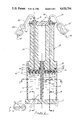
- FIG. 1 is a cross-sectional elevation view detailing the linear gradient former of the present invention
- FIG. 2 is a top plan view, partially in cross section, of the linear gradient former of the present invention taken along line 2--2 of FIG. 1;
- FIG. 3 is a cross-sectional elevation view, partially broken away, of the gradient former of the present invention taken along line 3--3 of FIG. 1;
- FIG. 4 is a cross-sectional elevation view, partially broken away, of the gradient former of the present invention taken along line 4--4 of FIG. 1;
- FIG. 5 is an elevation view, partially in cross-section, of an alternate embodiment of the linear gradient former of the present invention.
- FIG. 6 is a schematic electrical drawing showing the operation of the electrical stirrer depicted in FIG. 5;
- FIG. 7 is an elevation view, partially broken away, showing the gradient former of the present invention arranged for obtaining exponential gradients.
- FIG. 8 is a cross-sectional elevation view, partially broken away, of an alternate embodiment of the linear gradient former for large volume gradients, where a sight leveling rod is employed.
- linear gradient former assembly 1 comprises two identical cylinders 5 & 6. Cylinder 5 is mounted to a base 7, and thereby forms a storage chamber 8. Cylinder 6 is also mounted to base 7, thereby forming a mixing chamber 9.
- Base 7 contains an exit portal 10, shown in FIG. 4, perpendicular to the base 7 and located within cylindrical wall 5. A radial hole 11 in base 7 connects to the perpendicular portal 10.
- a fitting 12 is assembled into hole 11, and flexible hose or tubing 13 is attached to fitting 12. In this way, any fluid contained in cylinder 5 is able to exit storage chamber 8 through the portal 10, connecting hole 11 and fitting 12 into hose 13.
- Storage chamber tubing 13 is connected to mixing chamber 9 by a fitting 15.
- a tube clamp 16 is positioned along tubing 13 in order to controllably shut off or meter the flow rate between storage chamber 8 and mixing chamber 9. If desired, a metering valve could be used instead of a clamp 16 to restrict flow rate.
- mixing chamber base 7 also contains radial holes 17 and 18 formed therein substantially opposite each other.
- portals 19 and 23 are formed in base 7 within cylindrical wall 6.
- Portal 19 connects to radial hole 17 while portal 23 connects to radial hole 18. In this way, fluid from storage chamber 8 is able to enter mixing chamber 9 through hole 17 and portal 19, and exit chamber 9 through portal 23 and hole 18.
- gradient former assembly 1 is mounted on a magnetic mixer which causes bar stirrer 20 to rotate during gradient forming operation.
- the fluids exit mixing chamber 9 through portal 23, which meets with hole 18.
- a haudraulic fitting 24 is assembled to hole 18 and flexible tubing 25 is connected to fitting 24.
- a tube clamp 26 is used to shut off or restrict the flow from mixing chamber 9. After fluids 21 and 22 mix, they exit via hole 27 in flexible tubing 25. If desired, a metering valve could be sustituted for clamp 26 in order to shut off or create a restriction to flow rate.
- the last major component of gradient former assembly 1 of the present invention is the piston assembly.
- the piston assembly consists of two identical pistons 28 and 29. Pistons 28 and 29 utilize o-ring seals 30 and 31, which are held in place by o-ring grooves 32 and 33. Piston 28 is inserted into cylinder 5 and piston 29 is inserted into cylinder 6. Pistons 28 and 29 preferably incorporate conical shaped end faces 34 and 35, which are shaped to encourage air bubbles and liquid to enter into portal 36 of piston 28 and portal 37 of piston 29. Portal 36 runs axially through the center of piston 28, where fitting 38 is attached to the top of piston 28. Flexible tube 39 is attached to fitting 38 and tube 39 is used to carry fluid through hole 40 of tube 39 from a reservoir, which holds the fluid for storage chamber housed by cylinder 5 of linear gradient former assembly 1.
- Portal 37 runs axially through the center of piston 29, where fitting 41 is attached to top of piston 29.
- Flexible tube 42 is attached to fitting 41 and tube 42 is used to carry fluid through hole 43 of tube 42 from a second reservoir, which holds fluid for mixing chamber 9, housed by cylinder 6 of linear gradient former assembly 1.
- a tube clamp 44 is used to open or shut off flow in flexible tube 42.
- Tube clamp 45 is used to open or shut off flow in tube 39.
- gravity flow from a gradient former is desirable, such as in low pressure column chromatography, where fluid pressures much greater than atmospheric pressure can destroy sensitive samples for biotechnology applications.
- the present invention can be used to make an accurate gravity flow linear gradient because the fluid level in each chamber can be controlled to drop at the same rate by venting air into or out of each of the chambers.
- the linear gradient former is arranged as shown in FIG. 1.
- flexible tubes 39 and 42 are removed from their respective reservoirs.
- Screw clamps or metering type valves should be substituted for tube clamps 44 and 45.
- the gravity flow linear gradient is started by opening the downstream clamps 26 and 16.
- the level of fluids 21 and 22 is controlled to drop at the same rate by venting air into or out of chambers 8 and 9 through holes 40 and 43, which connect to holes 36 and 37.
- Dual piston assembly 47 can be pushed into cylinders 5 and 6 to assure the fluid levels in each chamber drop at the same rate.
- pistons 28 and 29 are equal in length, they provide a means to aid the eye in assuring the liquids 21 and 22 drop at the same rate in each chamber.
- the reservoirs and mixing chamber cylinders are made of clear material such as clear acrylic, glass, polycarbonate, or other machinable or moldable material. A chemical resistant material may be necessary in some cases.
- level rod 58 can be used instead of piston assembly 47. Level rod 58 slides up and down wires 59 and 60, which are attached by their ends to cylinders 5 and 6.
- Vt Volume of gradient already withdrawn at time t
- Magnetic stirrer assembly 49 consists of magnet 51, which is mounted to shaft of motor 52, and motor 52 is attached to housing 53. Motor 52 is powered by battery 54, which is held by battery holder 55, which is attached to housing 53. Knob 56 controls speed of motor 52, which rotates magnet 51. Magnet 51 causes Teflon-coated bar magnet 20 to rotate via its rotating magnetic field. Knob 56 rotates a potentiometer 57, which controls speed of motor 52, as described by FIG. 6.
- FIG. 7 the preferred embodiment for an exponential gradient former is shown.
- clamps 16 and 26 are closed off prior to filling chambers 8 and 9.
- Piston 29 is inserted into cylinder 6 and chamber 9 is filled with fluid 22 to desired volume via sucking fluid from reservoir via tubing 42. Piston 29 is held in place by a laboratory stand. Once volume of chamber 9 is established by piston 29 and cylinder 6, piston 29 does not move during exponential gradient forming.
- Piston 28 is inserted into cylinder 5, forming chamber 8. Chamber 8 is filled with fluid 21, as explained previously in FIGS. 1, 2, 3 and 4.
- the two downstream clamps 16 and 26 are closed and clamp 45 is opened. Retracting piston 28 causes fluid to be sucked from the reservoir via hole 40 into chamber 8.
- Exponential gradient can be continued by opening or closing the correct valves, as previously explained. A new gradient can be made by repeating the above cycle.
- An exponential gradient is produced by withdrawing liquid from the mixing chamber, the volume of which is kept constant. Liquid flows into the mixing chamber from the storage chamber, where the volume is allowed to diminish. If the mixing chamber contains the liquid of lesser concentration, the resulting gradient profile is convex exponential. If the mixing chamber contains the higher density liquid, the resulting profile is concave exponential. The smaller the volume of the mixing chamber, the more convex or concave the gradient. Exponential gradients can be described by the following relationship (See reference 1);
- Vm volume of mixing chamber
- ⁇ means that e is raised to the power of -(Vt/Vm).
- the mixing chamber fluid level is controlled by the air vent hole 130 in the piston 131, where hydraulic fitting 136 and flexible tubing 137 are also connected and the tube screw clamp 135 is used to meter the rate air enters the mixing chamber. If air is vented rapidly, then the fluid level moves rapidly. Proper adjustment of air vent valve 135 enables the operator to control the rate fluid drops in the mixing chamber. The operator views and compares the fluid level in each chamber to assure fluids are dropping at the same rate. Adjustments are made to the vent valve, if necessary. In some cases, when forming density gradients, it may be necessary to throttle the flow rate using screw clamp 138 of the fluid coming from the storage chamber if the storage chamber fluid density is much greater than the density of the fluid in the mixing chamber.
- a movable fluid level comparing rod spans across the front of the storage and mixing chambers to aid in assuring that the fluid in each chamber are identical.
- an elongated alignment rod 127 is provided.
- Rod 127 preferably pivots about the axis defined by holding pin 146.
- a bubble leveling device 123 is used to assure position rod 127 is perfectly horizontal.
- level device 123 is positioned away from pivot pin 146 to create a counter balance of the weight of rod 127.
- the fluid level control assembly also incorporates a slider 147 and a rod supporting arm 126.
- Slider 147 incorporates pin 146 and securely retains rod 127.
- slider 146 is movably mounted to arm 126 for sliding movement along the entire length thereof.
- arm 126 is attached to the storage chamber cover 124.
- Linear gradient former 150 is mounted on separate bases so it can be converted into an exponential gradient former.
- An exponential gradient former is made by elevating the storage chamber 133 above the mixing chamber 132 and placing storage chamber 133 on a pedestal. Fitting 139 is connected to flexible tubing 137 and tube clamp 138 is closed. Fluid flows from chamber 133 into chamber 132 where it is mixed and it exits as an exponential gradient. The fluid leveling apparatus is not needed for exponential gradient forming.
Abstract
Description
Ct=Cm+(Cr-Cm )(Vt/2Vo)
Ct=Cr-(Cr-Cm) e↑-(Vt/Vm)
Claims (8)
Priority Applications (1)
| Application Number | Priority Date | Filing Date | Title |
|---|---|---|---|
| US06/673,278 US4620794A (en) | 1984-11-20 | 1984-11-20 | Gradient formers |
Applications Claiming Priority (1)
| Application Number | Priority Date | Filing Date | Title |
|---|---|---|---|
| US06/673,278 US4620794A (en) | 1984-11-20 | 1984-11-20 | Gradient formers |
Publications (1)
| Publication Number | Publication Date |
|---|---|
| US4620794A true US4620794A (en) | 1986-11-04 |
Family
ID=24701992
Family Applications (1)
| Application Number | Title | Priority Date | Filing Date |
|---|---|---|---|
| US06/673,278 Expired - Lifetime US4620794A (en) | 1984-11-20 | 1984-11-20 | Gradient formers |
Country Status (1)
| Country | Link |
|---|---|
| US (1) | US4620794A (en) |
Cited By (11)
| Publication number | Priority date | Publication date | Assignee | Title |
|---|---|---|---|---|
| US4834854A (en) * | 1987-08-20 | 1989-05-30 | Fuji Photo Film Co., Ltd. | Method of making an electrophoresis medium |
| US5445614A (en) * | 1993-10-20 | 1995-08-29 | Habley Medical Technology Corporation | Pharmaceutical storage and mixing syringe |
| US6197579B1 (en) | 1997-02-14 | 2001-03-06 | Dendreon Corporation | Cell washing device and method |
| US6290105B1 (en) * | 1999-11-08 | 2001-09-18 | John Cosentino | Variable volume storage device |
| WO2002096545A1 (en) * | 2001-05-25 | 2002-12-05 | Ticona Gmbh | Highly diverse mixtures, method for the production and use thereof |
| US20050272146A1 (en) * | 2004-06-04 | 2005-12-08 | Geoffrey Hodge | Disposable bioreactor systems and methods |
| US20080019211A1 (en) * | 2004-12-01 | 2008-01-24 | Hurlimann Hans P | Device And Method For Mixing Substances, Mixing Reactor And Method For Continuously Ejecting A Treated Substance Using Said Mixing Reactor |
| US20080139865A1 (en) * | 2006-07-14 | 2008-06-12 | Xcellerex, Inc. | Environmental containment systems |
| US20110290826A1 (en) * | 2010-06-01 | 2011-12-01 | Harris David R | Structure for Storing Perishable Liquid |
| CN107949306A (en) * | 2015-09-04 | 2018-04-20 | 雀巢产品技术援助有限公司 | Foaming machine with controlled outlet |
| US11033141B2 (en) * | 2016-01-14 | 2021-06-15 | Smiics Gmbh | Device for preparing baby food |
Citations (4)
| Publication number | Priority date | Publication date | Assignee | Title |
|---|---|---|---|---|
| US2131488A (en) * | 1937-07-17 | 1938-09-27 | Lubrication Corp | Dispenser |
| GB793277A (en) * | 1955-01-14 | 1958-04-16 | Jules Maillard | Improvements in and relating to an apparatus for delivering different materials in predetermined proportions |
| DE1161140B (en) * | 1956-12-04 | 1964-01-09 | Daimler Benz Ag | Device for mixing viscous liquids in an adjustable ratio with reciprocally driven conveyor pumps |
| US3443520A (en) * | 1967-09-11 | 1969-05-13 | Int Equipment Co | Gradient forming pumps and method |
-
1984
- 1984-11-20 US US06/673,278 patent/US4620794A/en not_active Expired - Lifetime
Patent Citations (4)
| Publication number | Priority date | Publication date | Assignee | Title |
|---|---|---|---|---|
| US2131488A (en) * | 1937-07-17 | 1938-09-27 | Lubrication Corp | Dispenser |
| GB793277A (en) * | 1955-01-14 | 1958-04-16 | Jules Maillard | Improvements in and relating to an apparatus for delivering different materials in predetermined proportions |
| DE1161140B (en) * | 1956-12-04 | 1964-01-09 | Daimler Benz Ag | Device for mixing viscous liquids in an adjustable ratio with reciprocally driven conveyor pumps |
| US3443520A (en) * | 1967-09-11 | 1969-05-13 | Int Equipment Co | Gradient forming pumps and method |
Cited By (18)
| Publication number | Priority date | Publication date | Assignee | Title |
|---|---|---|---|---|
| US4834854A (en) * | 1987-08-20 | 1989-05-30 | Fuji Photo Film Co., Ltd. | Method of making an electrophoresis medium |
| US5445614A (en) * | 1993-10-20 | 1995-08-29 | Habley Medical Technology Corporation | Pharmaceutical storage and mixing syringe |
| US6197579B1 (en) | 1997-02-14 | 2001-03-06 | Dendreon Corporation | Cell washing device and method |
| US6290105B1 (en) * | 1999-11-08 | 2001-09-18 | John Cosentino | Variable volume storage device |
| WO2002096545A1 (en) * | 2001-05-25 | 2002-12-05 | Ticona Gmbh | Highly diverse mixtures, method for the production and use thereof |
| US20040145077A1 (en) * | 2001-05-25 | 2004-07-29 | Dietrich Fleischer | Highly diverse mixtures, method for the production, and use thereof |
| US7629167B2 (en) | 2004-06-04 | 2009-12-08 | Xcellerex, Inc. | Disposable bioreactor systems and methods |
| US20050272146A1 (en) * | 2004-06-04 | 2005-12-08 | Geoffrey Hodge | Disposable bioreactor systems and methods |
| US8118474B2 (en) * | 2004-12-01 | 2012-02-21 | Hurlimann Hans P | Device and method for mixing substances, mixing reactor and method for continuously ejecting a treated substance using said mixing reactor |
| US20080019211A1 (en) * | 2004-12-01 | 2008-01-24 | Hurlimann Hans P | Device And Method For Mixing Substances, Mixing Reactor And Method For Continuously Ejecting A Treated Substance Using Said Mixing Reactor |
| US20080139865A1 (en) * | 2006-07-14 | 2008-06-12 | Xcellerex, Inc. | Environmental containment systems |
| US7819934B2 (en) | 2006-07-14 | 2010-10-26 | Xcellerex, Inc. | Environmental containment systems |
| US20110290826A1 (en) * | 2010-06-01 | 2011-12-01 | Harris David R | Structure for Storing Perishable Liquid |
| CN107949306A (en) * | 2015-09-04 | 2018-04-20 | 雀巢产品技术援助有限公司 | Foaming machine with controlled outlet |
| US20180243766A1 (en) * | 2015-09-04 | 2018-08-30 | Nestec S.A. | Foaming device with controlled outlet |
| US10464085B2 (en) * | 2015-09-04 | 2019-11-05 | Societe Des Produits Nestle S.A. | Foaming device with controlled outlet |
| CN107949306B (en) * | 2015-09-04 | 2021-10-01 | 雀巢产品有限公司 | Foaming device with controlled outlet |
| US11033141B2 (en) * | 2016-01-14 | 2021-06-15 | Smiics Gmbh | Device for preparing baby food |
Similar Documents
| Publication | Publication Date | Title |
|---|---|---|
| US4620794A (en) | Gradient formers | |
| JP7264944B2 (en) | Viscometer and its usage | |
| US3963151A (en) | Fluid dispensing system | |
| US3991616A (en) | Automatic pipetter | |
| US3222135A (en) | Apparatus for the preparation of fluid samples | |
| US3012863A (en) | Apparatus for the preparation of laboratory test samples | |
| EP0607102A1 (en) | Dispensing appliance for at least two components | |
| US3805998A (en) | Dispensing pipette | |
| JP6169862B2 (en) | Pipetting device and manufacturing method thereof | |
| US3982899A (en) | Fluid handling apparatus | |
| US20010036425A1 (en) | Device for transferring samples of micro-amounts of liquids | |
| US3939688A (en) | Volumetric calibration | |
| EP2417038B1 (en) | Pump-less toner dispenser | |
| US3770169A (en) | Motorized liquid dispenser with an accurate dispensing volume adjustment | |
| JP2021032900A (en) | Device and method for supplying liquid medium | |
| JP2622102B2 (en) | Compounding device for forming gradient gel | |
| US4269327A (en) | Device for carrying out high precision dilutions and dosages of liquids, particularly biological liquids | |
| US3250441A (en) | Liquid-dispensing apparatus | |
| US3127062A (en) | Semi-automatic sampling and diluting apparatus | |
| US5674052A (en) | Pinch pump having selectable pressure plate sizes and a flexible tube with attachment ribs | |
| US5996854A (en) | Liquid dispenser with coaxial piston and rod for dispensing a precise volume | |
| US11229905B2 (en) | Method and apparatus for dispensing precise aliquots of liquid | |
| US3138290A (en) | Automatic diluting apparatus | |
| US3883044A (en) | Micropipetter, especially for the discharge of a sample and a diluent | |
| CN210460974U (en) | Accurate input ware of biochemical appearance reagent |
Legal Events
| Date | Code | Title | Description |
|---|---|---|---|
| AS | Assignment |
Owner name: JULE INC., 4444 MADISON AVENUE, TRUMBULL, CT., 0 Free format text: ASSIGNMENT OF ASSIGNORS INTEREST.;ASSIGNOR:LEKA, GEORGE T.;REEL/FRAME:004376/0684 Effective date: 19841115 |
|
| STCF | Information on status: patent grant |
Free format text: PATENTED CASE |
|
| FEPP | Fee payment procedure |
Free format text: PAYOR NUMBER ASSIGNED (ORIGINAL EVENT CODE: ASPN); ENTITY STATUS OF PATENT OWNER: SMALL ENTITY |
|
| FPAY | Fee payment |
Year of fee payment: 4 |
|
| AS | Assignment |
Owner name: CONNECTICUT INNOVATIONS INCORPORATED, A CORP. OF C Free format text: SECURITY INTEREST;ASSIGNOR:JULE, INC.;REEL/FRAME:005285/0087 Effective date: 19900404 |
|
| FPAY | Fee payment |
Year of fee payment: 8 |
|
| FPAY | Fee payment |
Year of fee payment: 12 |