US4634212A - Terminal block mount - Google Patents
Terminal block mount Download PDFInfo
- Publication number
- US4634212A US4634212A US06/618,629 US61862984A US4634212A US 4634212 A US4634212 A US 4634212A US 61862984 A US61862984 A US 61862984A US 4634212 A US4634212 A US 4634212A
- Authority
- US
- United States
- Prior art keywords
- terminal block
- positioning guide
- guide fins
- tab members
- flanges
- Prior art date
- Legal status (The legal status is an assumption and is not a legal conclusion. Google has not performed a legal analysis and makes no representation as to the accuracy of the status listed.)
- Expired - Lifetime
Links
Images


Classifications
-
- H—ELECTRICITY
- H01—ELECTRIC ELEMENTS
- H01R—ELECTRICALLY-CONDUCTIVE CONNECTIONS; STRUCTURAL ASSOCIATIONS OF A PLURALITY OF MUTUALLY-INSULATED ELECTRICAL CONNECTING ELEMENTS; COUPLING DEVICES; CURRENT COLLECTORS
- H01R25/00—Coupling parts adapted for simultaneous co-operation with two or more identical counterparts, e.g. for distributing energy to two or more circuits
- H01R25/16—Rails or bus-bars provided with a plurality of discrete connecting locations for counterparts
- H01R25/164—Connecting locations formed by flush mounted apparatus
Definitions
- This invention relates to the mounting of an electrical terminal block within a frame member and more particularly to the mounting of a terminal block within the raceway structural frame of a space dividing wall panel system.
- Copending application Ser. No. 618,603, filed June 18, 1984 for PANEL BASE ELECTRICAL RACEWAY U.S. Pat. No. 4593505, is directed to a novel raceway construction for the distribution of electrical power as well as communication cables in the base of a space dividing wall panel.
- the terminal block mount of this invention is directed to a novel mechanism for mounting an electrical terminal block within such a raceway.
- the terminal block mount of this invention includes frame means having a terminal block receiving aperture therein with detent means on the frame means extending into the terminal block receiving aperture from opposite sides thereof and a terminal block having a pair of opposed sloped flexible tab members on opposite surfaces thereof with each of the pairs of tab members defining a slot therebetween for receiving the detent means.
- the terminal block is slipped into the terminal block receiving aperture with the opposed detents depressing one of the tab members on each side of the terminal block until the detent slips into the slot between the opposed tab members, thereby retaining the terminal block within the terminal block receiving aperture.
- the frame means includes horizontal flange means on each side of the detent means for supporting and locating the terminal block therein and the terminal block includes positioning guide fins on each side of the flexible tabs with the positioning guide fins coacting with the flanges to orient and support the terminal block within the terminal block receiving aperture when the detent means are locked in the slot between the opposed flexible tab members.
- FIG. 1 is a perspective view of a space dividing wall panel and raceway including the terminal block mount of this invention
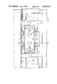
- FIG. 2 is a side elevation view of the terminal block mount
- FIG. 3 is an end elevation view of the terminal block mount of this invention.
- FIG. 4 is a partial sectional view taken along the line IV--IV of FIG. 2.
- FIG. 1 a perspective view of a space dividing wall panel generally designated 10 having suspended from its bottom edge an electrical raceway of the type disclosed in copending application Ser. No. 618,603, filed June 8, 1984 for PANEL MOUNTED ELECTRICAL RACEWAY U.S. Pat. No. 4593505.
- the raceway 12 principally comprises a pair of spaced frame members 14 which are interconnected by an elongated inverted T-shaped rail member 16.
- Each of the frame members 14 include a terminal block receiving aperture 18 therein which serves to mount an electrical terminal block 20 in the raceway 12.
- the terminal block mount of this invention includes in combination the frame member 14 and the terminal block 20.
- the frame member 14 which is preferably constructed from two identical parts of 20 gauge cold rolled steel welded back to back to form a unitary structure, includes a pair of rigid detents 22 which extend into the aperture 18 from the top and bottom edges thereof.
- a pair of planar upper guide flanges 24 are situated on each side of the upper detent 22 and a pair of larger guide flanges 26 are situated on each side of the lower detent 22 and essentially surround the detent.
- the guide flanges 26 have, at their lateral edges, vertical guide flanges 28 which extend upwardly into the aperture 18 to form a guide in connection with the flanges 24 and 26 for inserting the terminal block 20 into the mounting aperture.
- the terminal block 20 has located centrally of its top and bottom surfaces inwardly directed, opposed, sloped, flexible tab members 30 with the inward ends of the tab members 30 forming a slot 32 therebetween.
- On each side of the flexible tab members 30 are rigid guide fins 34 on both the top and bottom surfaces of the terminal block.
- the remainder of the electrical terminal block 20 is essentially conventional and includes male terminal extensions 36 on each end thereof for interconnection with flexible jumper cables (not shown). Since each side of the terminal block is designed to carry three separate circuits interchangeable convenience outlets 38 may be selectively plugged into the side of the terminal block and are constructed and arranged to extend through the base covers 40 of the panel mounted electrical raceway 12.
- the terminal block 20 is placed between the top flanges 24 and the bottom flanges 26 with the outermost guide fins 34 on the bottom of the terminal block sliding within the vertical guide flanges 28.
- the outermost guide fins 34 on the top surface of the terminal block are spaced slightly farther apart than the outermost guide fins 34 on the bottom of the terminal block to prevent the inadvertent insertion of the terminal block upside down. More specifically, the guide fins 34 on the top side of the terminal block are spaced a sufficient distance apart that they cannot be inserted between the vertical guide flanges 28.
- the flexible tab members 30 on one side of the top and bottom of the terminal block are merely depressed with a screwdriver or similar tool and the detent slipped over the depressed tab to quickly and easily remove the terminal block from the support frame.
Abstract
Description
Claims (7)
Priority Applications (2)
| Application Number | Priority Date | Filing Date | Title |
|---|---|---|---|
| US06/618,629 US4634212A (en) | 1984-06-08 | 1984-06-08 | Terminal block mount |
| CA000482804A CA1235207A (en) | 1984-06-08 | 1985-05-30 | Terminal block mount |
Applications Claiming Priority (1)
| Application Number | Priority Date | Filing Date | Title |
|---|---|---|---|
| US06/618,629 US4634212A (en) | 1984-06-08 | 1984-06-08 | Terminal block mount |
Publications (1)
| Publication Number | Publication Date |
|---|---|
| US4634212A true US4634212A (en) | 1987-01-06 |
Family
ID=24478465
Family Applications (1)
| Application Number | Title | Priority Date | Filing Date |
|---|---|---|---|
| US06/618,629 Expired - Lifetime US4634212A (en) | 1984-06-08 | 1984-06-08 | Terminal block mount |
Country Status (2)
| Country | Link |
|---|---|
| US (1) | US4634212A (en) |
| CA (1) | CA1235207A (en) |
Cited By (21)
| Publication number | Priority date | Publication date | Assignee | Title |
|---|---|---|---|---|
| US4918886A (en) * | 1989-05-31 | 1990-04-24 | Harpers | Raceway system for modular wall panels |
| US5015203A (en) * | 1989-12-26 | 1991-05-14 | Amp Incorporated | Power distribution unit having improved junction box |
| US5065556A (en) * | 1990-05-15 | 1991-11-19 | Westinghouse Electric Corp. | Space dividing partition system having an electrical raceway |
| US5092786A (en) * | 1989-02-21 | 1992-03-03 | Steelcase Inc. | Modular powerway for office furniture and the like |
| US5152698A (en) * | 1989-02-07 | 1992-10-06 | Steelcase Inc. | Floor track system for office furniture and the like |
| US5158472A (en) * | 1989-02-21 | 1992-10-27 | Steelcase Inc. | Modular powerway for office furniture and the like |
| US5164544A (en) * | 1991-03-13 | 1992-11-17 | Westinghouse Electric Corp. | Electrified space dividing panel |
| US5178555A (en) * | 1991-10-02 | 1993-01-12 | Amp Incorporated | Installation of junction boxes along a raceway |
| WO1993014827A1 (en) * | 1992-01-24 | 1993-08-05 | Mattel, Inc. | Improved sound producing game bat |
| US5349135A (en) * | 1992-06-08 | 1994-09-20 | Rosemount Office Systems, Inc. | Fastener for electrical power distribution in divider panels |
| US5785551A (en) * | 1995-03-28 | 1998-07-28 | Libby; Robert A. | Quick connect electrical box |
| US5886295A (en) * | 1997-07-18 | 1999-03-23 | Steelcase Inc. | Modular utility distribution mounting system |
| US5975938A (en) * | 1998-06-03 | 1999-11-02 | Robert A. Libby | Quick connect electrical connector for multi conductor insulated cable wiring |
| US6282854B1 (en) | 1998-06-05 | 2001-09-04 | Trendway Corporation | Frame-based workplace system |
| US6374548B1 (en) | 1998-06-05 | 2002-04-23 | Trendway Corporation | Column-based workspace definition system |
| US6491535B1 (en) * | 2001-10-01 | 2002-12-10 | Pent Assemblies, Inc. | Electrical distribution system with keyed channel arrangement |
| US6575777B2 (en) | 2000-10-30 | 2003-06-10 | Kimball International, Inc. | Partition wiring system |
| US20040045232A1 (en) * | 2002-09-05 | 2004-03-11 | Gerber Gregory P. | Receptacle mounting converter |
| US20050064759A1 (en) * | 2003-09-23 | 2005-03-24 | Libby Robert A. | Hinged electrical connector for insulated cable |
| US20090293388A1 (en) * | 2008-05-27 | 2009-12-03 | Feldpausch Michael J | Partition assembly |
| US8558110B1 (en) * | 2009-02-05 | 2013-10-15 | Hubbell Incorporated | Multi-use electrical box |
Citations (8)
| Publication number | Priority date | Publication date | Assignee | Title |
|---|---|---|---|---|
| US2292394A (en) * | 1939-12-19 | 1942-08-11 | Pierce John B Foundation | Electrical wiring system |
| US2983897A (en) * | 1957-12-11 | 1961-05-09 | Bar-carried detachable electrical terminal blocks | |
| US3474392A (en) * | 1967-09-05 | 1969-10-21 | Alexander Norden | Terminal-block assemblies and mounting rails therefor |
| US3559813A (en) * | 1968-08-02 | 1971-02-02 | Thomas & Betts Corp | Module mounting system |
| US4073563A (en) * | 1974-11-05 | 1978-02-14 | Switchcraft, Inc. | Structure for electrical connections and panel assembly |
| DE2736079A1 (en) * | 1977-08-10 | 1979-02-22 | Air Lb Gmbh | Terminal block of modular construction clipped to rails - has spring-loaded contact brackets with each limb divided into prongs |
| US4203639A (en) * | 1978-05-26 | 1980-05-20 | Steelcase, Inc. | Panel wiring system |
| US4278834A (en) * | 1978-12-06 | 1981-07-14 | Westinghouse Electric Corp. | Versatile, electrified space dividing wall panel system |
-
1984
- 1984-06-08 US US06/618,629 patent/US4634212A/en not_active Expired - Lifetime
-
1985
- 1985-05-30 CA CA000482804A patent/CA1235207A/en not_active Expired
Patent Citations (9)
| Publication number | Priority date | Publication date | Assignee | Title |
|---|---|---|---|---|
| US2292394A (en) * | 1939-12-19 | 1942-08-11 | Pierce John B Foundation | Electrical wiring system |
| US2983897A (en) * | 1957-12-11 | 1961-05-09 | Bar-carried detachable electrical terminal blocks | |
| US3474392A (en) * | 1967-09-05 | 1969-10-21 | Alexander Norden | Terminal-block assemblies and mounting rails therefor |
| US3559813A (en) * | 1968-08-02 | 1971-02-02 | Thomas & Betts Corp | Module mounting system |
| US4073563A (en) * | 1974-11-05 | 1978-02-14 | Switchcraft, Inc. | Structure for electrical connections and panel assembly |
| DE2736079A1 (en) * | 1977-08-10 | 1979-02-22 | Air Lb Gmbh | Terminal block of modular construction clipped to rails - has spring-loaded contact brackets with each limb divided into prongs |
| US4203639A (en) * | 1978-05-26 | 1980-05-20 | Steelcase, Inc. | Panel wiring system |
| US4203639B1 (en) * | 1978-05-26 | 1992-06-30 | L Vanden Hoek Harold | |
| US4278834A (en) * | 1978-12-06 | 1981-07-14 | Westinghouse Electric Corp. | Versatile, electrified space dividing wall panel system |
Cited By (25)
| Publication number | Priority date | Publication date | Assignee | Title |
|---|---|---|---|---|
| US5152698A (en) * | 1989-02-07 | 1992-10-06 | Steelcase Inc. | Floor track system for office furniture and the like |
| US5092786A (en) * | 1989-02-21 | 1992-03-03 | Steelcase Inc. | Modular powerway for office furniture and the like |
| US5158472A (en) * | 1989-02-21 | 1992-10-27 | Steelcase Inc. | Modular powerway for office furniture and the like |
| US4918886A (en) * | 1989-05-31 | 1990-04-24 | Harpers | Raceway system for modular wall panels |
| US5015203A (en) * | 1989-12-26 | 1991-05-14 | Amp Incorporated | Power distribution unit having improved junction box |
| US5065556A (en) * | 1990-05-15 | 1991-11-19 | Westinghouse Electric Corp. | Space dividing partition system having an electrical raceway |
| US5164544A (en) * | 1991-03-13 | 1992-11-17 | Westinghouse Electric Corp. | Electrified space dividing panel |
| US5178555A (en) * | 1991-10-02 | 1993-01-12 | Amp Incorporated | Installation of junction boxes along a raceway |
| WO1993014827A1 (en) * | 1992-01-24 | 1993-08-05 | Mattel, Inc. | Improved sound producing game bat |
| US5349135A (en) * | 1992-06-08 | 1994-09-20 | Rosemount Office Systems, Inc. | Fastener for electrical power distribution in divider panels |
| US5785551A (en) * | 1995-03-28 | 1998-07-28 | Libby; Robert A. | Quick connect electrical box |
| US5886295A (en) * | 1997-07-18 | 1999-03-23 | Steelcase Inc. | Modular utility distribution mounting system |
| US5975938A (en) * | 1998-06-03 | 1999-11-02 | Robert A. Libby | Quick connect electrical connector for multi conductor insulated cable wiring |
| US6282854B1 (en) | 1998-06-05 | 2001-09-04 | Trendway Corporation | Frame-based workplace system |
| US6374548B1 (en) | 1998-06-05 | 2002-04-23 | Trendway Corporation | Column-based workspace definition system |
| US6575777B2 (en) | 2000-10-30 | 2003-06-10 | Kimball International, Inc. | Partition wiring system |
| US6491535B1 (en) * | 2001-10-01 | 2002-12-10 | Pent Assemblies, Inc. | Electrical distribution system with keyed channel arrangement |
| US20040045232A1 (en) * | 2002-09-05 | 2004-03-11 | Gerber Gregory P. | Receptacle mounting converter |
| US20050064759A1 (en) * | 2003-09-23 | 2005-03-24 | Libby Robert A. | Hinged electrical connector for insulated cable |
| US7144269B2 (en) | 2003-09-23 | 2006-12-05 | Aslan Industries Corporation | Hinged electrical connector for insulated cable |
| US20090293388A1 (en) * | 2008-05-27 | 2009-12-03 | Feldpausch Michael J | Partition assembly |
| US8910435B2 (en) * | 2008-05-27 | 2014-12-16 | Steelcase Inc. | Partition assembly |
| US10626600B2 (en) | 2008-05-27 | 2020-04-21 | Steelcase Inc. | Partition assembly |
| US10669713B2 (en) | 2008-05-27 | 2020-06-02 | Steelcase Inc. | Partition assembly |
| US8558110B1 (en) * | 2009-02-05 | 2013-10-15 | Hubbell Incorporated | Multi-use electrical box |
Also Published As
| Publication number | Publication date |
|---|---|
| CA1235207A (en) | 1988-04-12 |
Similar Documents
| Publication | Publication Date | Title |
|---|---|---|
| US4634212A (en) | Terminal block mount | |
| US4712232A (en) | Multiple telephone jack slide assembly | |
| US4593505A (en) | Panel base electrical raceway | |
| US6242698B1 (en) | Interchangeable adapter face plates | |
| US4150867A (en) | Pre-wired terminal connecting block | |
| US4990722A (en) | Ducting for electrical conductors and the like with stiffening arrangement and corresponding clamp | |
| US5594207A (en) | Self-locking divider plate for an electrical box | |
| US3868158A (en) | Module rack for connection boxes of printed-circuit cards | |
| US6318680B1 (en) | Cable trough arrangement | |
| US4308418A (en) | Arrangement for hard wiring movable room divider panels | |
| US6158180A (en) | Mounting device for communications conduit connector | |
| US7183504B2 (en) | Electrical floor access module system | |
| US7714237B2 (en) | Electrical apparatus and supporting frame for wall-mounting same | |
| US3573373A (en) | Cable terminating system for key telephone closets | |
| US4336673A (en) | Mosaic display panel | |
| JPS5822869B2 (en) | Bracket for use with terminal block | |
| US5980003A (en) | Detachable case assembly for computer | |
| US5349135A (en) | Fastener for electrical power distribution in divider panels | |
| US4353469A (en) | Support shelf for printed circuit boards | |
| US3088055A (en) | Panel board chassis and wiring channel | |
| EP0037615A2 (en) | Suspended ceiling and coupling element for the same | |
| US4278315A (en) | System for interconnection of multiple insulated wires | |
| US3329763A (en) | Raceway | |
| US4355212A (en) | Wall telephone cradle assembly | |
| US4658418A (en) | Multiple telephone jack slide assembly |
Legal Events
| Date | Code | Title | Description |
|---|---|---|---|
| AS | Assignment |
Owner name: WESTINGHOUSE ELECTRIC CORPORATION WESTINGHOUSE BLD Free format text: ASSIGNMENT OF ASSIGNORS INTEREST.;ASSIGNORS:BOUNDY, BRUCE K.;MILLER, CRAIG M.;REEL/FRAME:004271/0757 Effective date: 19840607 |
|
| STCF | Information on status: patent grant |
Free format text: PATENTED CASE |
|
| FPAY | Fee payment |
Year of fee payment: 4 |
|
| FEPP | Fee payment procedure |
Free format text: PAYOR NUMBER ASSIGNED (ORIGINAL EVENT CODE: ASPN); ENTITY STATUS OF PATENT OWNER: LARGE ENTITY |
|
| FPAY | Fee payment |
Year of fee payment: 8 |
|
| AS | Assignment |
Owner name: NATIONSBANK, N.A., AS COLLATERAL AGENT, NORTH CARO Free format text: SECURITY AGREEMENT;ASSIGNOR:KNOLL, INC.;REEL/FRAME:007803/0214 Effective date: 19960228 |
|
| AS | Assignment |
Owner name: KNOLL, INC., PENNSYLVANIA Free format text: ASSIGNMENT OF ASSIGNORS INTEREST;ASSIGNOR:WESTINGHOUSE ELECTRIC CORPORATION;REEL/FRAME:007888/0022 Effective date: 19960229 |
|
| AS | Assignment |
Owner name: KNOLL, INC., PENNSYLVANIA Free format text: RELEASE BY SECURED PARTY;ASSIGNOR:NATIONSBANK, N.A. AS COLLATERAL AGENT;REEL/FRAME:008660/0504 Effective date: 19970806 |
|
| FPAY | Fee payment |
Year of fee payment: 12 |
|
| AS | Assignment |
Owner name: BANK OF AMERICA, N.A., AS COLLATERAL AGENT, NORTH Free format text: NOTICE OF GRANT OF SECURITY INTEREST;ASSIGNOR:KNOLL, INC.;REEL/FRAME:010360/0001 Effective date: 19991020 |
|
| AS | Assignment |
Owner name: KNOLL, INC., PENNSYLVANIA Free format text: RELEASE OF SECURITY INTEREST IN PATENT COLLATERAL (RF 010360/0001);ASSIGNOR:BANK OF AMERICA, N.A.;REEL/FRAME:015215/0024 Effective date: 20040928 |