US4635179A - Transformer rectifier - Google Patents
Transformer rectifier Download PDFInfo
- Publication number
- US4635179A US4635179A US06/794,043 US79404385A US4635179A US 4635179 A US4635179 A US 4635179A US 79404385 A US79404385 A US 79404385A US 4635179 A US4635179 A US 4635179A
- Authority
- US
- United States
- Prior art keywords
- transformer
- secondary winding
- rectifier assembly
- cores
- rectifier
- Prior art date
- Legal status (The legal status is an assumption and is not a legal conclusion. Google has not performed a legal analysis and makes no representation as to the accuracy of the status listed.)
- Expired - Fee Related
Links
Images


Classifications
-
- H—ELECTRICITY
- H02—GENERATION; CONVERSION OR DISTRIBUTION OF ELECTRIC POWER
- H02M—APPARATUS FOR CONVERSION BETWEEN AC AND AC, BETWEEN AC AND DC, OR BETWEEN DC AND DC, AND FOR USE WITH MAINS OR SIMILAR POWER SUPPLY SYSTEMS; CONVERSION OF DC OR AC INPUT POWER INTO SURGE OUTPUT POWER; CONTROL OR REGULATION THEREOF
- H02M3/00—Conversion of dc power input into dc power output
- H02M3/22—Conversion of dc power input into dc power output with intermediate conversion into ac
- H02M3/24—Conversion of dc power input into dc power output with intermediate conversion into ac by static converters
- H02M3/28—Conversion of dc power input into dc power output with intermediate conversion into ac by static converters using discharge tubes with control electrode or semiconductor devices with control electrode to produce the intermediate ac
- H02M3/325—Conversion of dc power input into dc power output with intermediate conversion into ac by static converters using discharge tubes with control electrode or semiconductor devices with control electrode to produce the intermediate ac using devices of a triode or a transistor type requiring continuous application of a control signal
- H02M3/335—Conversion of dc power input into dc power output with intermediate conversion into ac by static converters using discharge tubes with control electrode or semiconductor devices with control electrode to produce the intermediate ac using devices of a triode or a transistor type requiring continuous application of a control signal using semiconductor devices only
- H02M3/33569—Conversion of dc power input into dc power output with intermediate conversion into ac by static converters using discharge tubes with control electrode or semiconductor devices with control electrode to produce the intermediate ac using devices of a triode or a transistor type requiring continuous application of a control signal using semiconductor devices only having several active switching elements
Definitions
- This invention relates to the production of low DC voltages by the use of high frequency power conversion techniques in a power supply of minimum volume, and more particularly, to a transformer-rectifier assembly for producing low DC voltages.
- One approach to reducing output capacitor volume is to minimize the output filtering required.
- the output filtering requirements can be reduced by utilizing a physically integrated assembly of two magnetically independent transformers and two semiconductor rectifiers, arranged to minimize leakage and parasitic lead inductances, and the resultant voltage dropout during current commutation from one transformer-rectifier to the other. It is therefore an object of the present invention to provide a transformer rectifier assembly which eliminates the problems associated with prior art devices and will produce a rectified output of nearly pure DC voltage before filtering by minimizing the time required for current commutation between output rectifiers. Another object of the present invention is to provide a transformer rectifier assembly which minimizes leakage inductances by the physical integration of output transformers and rectifiers into a single assembly.
- an integrated transformer-rectifier assembly comprising first and second closed-loop cores of magnetic material, each core having a first portion provided with a primary winding, said primary windings being closely spaced apart and closely encircled throughout their entire length by a single turn secondary winding, said secondary winding having closely spaced ends on one side of said cores which are connected via rectifiers to a first output lead, a second output lead being connected to said secondary winding on the other side of said cores.
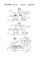
- FIG. 1 is a diagrammatic view of the construction of an embodiment of the transformer-rectifier assembly in accordance with the invention
- FIG. 2 is a sectional view of the transformer-rectifier assembly of FIG. 1;
- FIG. 3 is a sectional view of another embodiment of a transformer-rectifier assembly according to the invention.
- FIG. 4 is a schematic diagram of a power supply circuit using a transformer-rectifier assembly according to the present invention.
- FIG. 5 is a schematic diagram of an alternative power supply circuit using a transformer-rectifier assembly according to the present invention.
- FIG. 6 is a simplified diagrammatic view of an embodiment of the invention which includes an output inductance (choke);
- FIG. 7 is a diagrammatic view of another embodiment of the invention which does not have an output inductance.
- FIG. 8 is a sectional view of the output connection arrangement of FIG. 7.
- the transformer-rectifier assembly is comprised of a first closed-loop ferromagnetic core 11 and a second closed-loop ferromagnetic core 12.
- These ferromagnetic cores can be of a rectangular shape with a square or rectangular cross-section and can be made of a suitable magnetic material.
- a first primary winding 13 is wound around one leg 14 of the first ferromagnetic core 11.
- a second primary winding 15 is wound around one leg 16 of the second ferromagnetic core 12.
- the first ferromagnetic core 11 is placed adjacent to the second magnetic core 12 in a co-planar arrangement such that the primary windings 13 and 15 are in near contact as is shown at 17.
- a single turn secondary winding 18 is wound closely around the first primary winding 13 and second primary winding 15. This physical arrangement form two magnetically independent transformers.
- the secondary winding 18 can be made of a uniform sheet of conducting material, such as a metal foil, having closely spaced ends 19 and 20.
- the secondary winding 18 can also be made of a plurality of parallel conductors placed adjacent each other and wound around the primary windings 13 and 15.
- the ends 19 and 20 of the secondary winding 18 are connected via semiconductor rectifiers 21 and 22 to a conductive sheet 23 which is used as an output line of the secondary winding 18.
- the semiconductor rectifiers 21 and 22 can be rectifier pellets, which are an intermediate stage of fabrication between chips and fully packaged devices.
- the other output feeding line of the secondary winding 18 is shown at 24.
- This line 24 is positioned on an axis 29 perpendicular to the longitudinal and lateral axes, (A) and (B) respectively, of the ferromagnetic cores 11 and 12.
- the orientation of the feeding line 24, shown in FIG. 1, is positioned in a perpendicular orientation for the purpose of clarity, other positions will be readily apparent to those knowledgeable in this art.
- the output feeding line 24 is centrally located on the secondary winding 18 in such a position that the output current is forced to flow through alternate halves of the secondary winding by the primary currents. For example, when the primary winding 13 is energized, current will flow in one-half of the secondary winding 25 to connecting end 19, through rectifier 21 and then to the output line 23.
- the transformer-rectifier assembly 10 can be positioned in a circuit, over an insulator 27 and further positioned over a heat sink 28 for heat dissipation.
- rectifiers 21 and 22 are positioned directly beneath the first and second primary windings, 13 and 15 respectively, and connected between the first and second connecting ends, 19 and 20 respectively, of the secondary winding 18.
- Reference numeral 30 in FIG. 3 shows another embodiment of the transformer-rectifier assembly.
- the first connecting end 33 of the secondary winding 34 is positioned beneath an uncovered section of the first magnetic core 35.
- the second connecting end 36 is positioned underneath the uncovered or unshielded section of the second magnetic core 37.
- the first and second connecting ends 33 and 36, respectively, are electrically connected to a rectifier common connection 38 via rectifiers 31 and 32, respectively.
- This alternative rectifier arrangement provides a compact transformer-rectifier assembly of minimum height.
- the previously described transformer-rectifier assemblies can typically be used in d.c. power supply circuits such as shown in FIGS. 4 and 5.
- the circuit of FIG. 4 is a voltage fed transformer circuit which uses a choke input 41 for the output filter 42.
- the two transistor switches 43 and 44 are driven out of phase by control and drive circuits 45 and 46, respectively.
- the transistors 43 and 44 may be driven with slight to moderate conduction overlap; that is: transistors 43 and 44 may both be on for a fraction of the switching period.
- transistor 43 is on (conducting) and transistor 44 is off, the input voltage 47 is transformed down by the turns ratio of transformer 48 in the transformer-rectifier assembly 49.
- Transistor 44 is turned on before transistor 43 is turned off, but there is no significant change in the current flow in transformer 48 and transformer 49 until transistor 43 is turned off, at which time the current is commutated from transformer 48 and rectifier 50 to transformer 49 and rectifier 51 at a rate essentially limited by the total inductance in the circuit comprised of rectifiers 50, 51, and the leakage inductance of the transformer secondary.
- This total inductance is physically defined by the space between the first and second primary windings, and the space between the primary windings and the secondary winding.
- the voltage at the rectifier output will be approximately zero. This short voltage dropout is filtered by inductor 41 and capacitor 52.
- a similar commutation occurs from transformer 49 and rectifier 51 to transformer 48 and rectifier 50 when transistor 43 turns on and transistor 44 turns off.
- the circuit of FIG. 4 does not regulate the output voltage, but only transforms the input voltage 47 by a fixed ratio dependent on the transformer turns ratio and the switch and diode voltage drops.
- the input voltage 47 may be pre-regulated by any conventional means to regulate or control the output voltage.
- FIG. 5 The circuit of FIG. 5 is similar to that of FIG. 4 except that the filter inductor 41 shown in FIG. 4 has been "transformed” to the primary side 53 to form a "current fed” transformer circuit 54; operation is otherwise similar.
- Logic circuits, transistor switch drive circuits, and transformer magnetizing current reset circuits are not shown in FIGS. 4 and 5 for simplicity. These can easily be implemented by someone knowledgeable in the art.
- an output inductor is automatically formed by the transformer core sections not covered (or shielded) by the primary windings (the outside and end sections of the cores) and the single turn of conductor (input lead, paralleled secondaries and rectifiers, and output lead) through this core.
- the structure of this choke is shown in FIG. 6.
- the magnetic field of the choke flows around the outside legs 63 and 64 of the transformers only, and does not interact significantly with the transformer magnetic fields. This magnetic structure has two air gaps 65 and 66.
- conducting lines 61 and 62 enclose air gap 66 such that the feeding lines 61 and 62 are positioned in planes defined by the longitudinal axis (A) and the lateral axis (B) of the ferromagnetic cores.
- FIG. 7 If a current fed circuit such as is shown in FIG. 5 is to be used, this built-in inductance is detrimental and undesirable. This now undesirable output inductance can be removed by the use of output connections such as shown in FIG. 7.
- the feeding lines 71 and 72 shown in FIGS. 7 and 8 are positioned so as to go through the air gap 73 which prevents the output current from inducing a magnetic field in the cores 74 and 75. As can be seen in FIG. 7 and the sectional view shown in FIG.
- the feeding lines 71 and 72 are closely positioned parallel to each other and between primary windings 76 and 77 in planes defined by the longitudinal axis (A) and vertical axis (C) of the ferromagnetic cores such that no magnetic field is induced in the cores 74 and 75.
- the current in the secondary is also fed at the centre of the secondary winding such that it is forced to flow through alternate halves of the secondary winding by the primary currents as is discussed above.
Abstract
Description
Claims (18)
Priority Applications (2)
| Application Number | Priority Date | Filing Date | Title |
|---|---|---|---|
| US06/794,043 US4635179A (en) | 1985-10-25 | 1985-10-25 | Transformer rectifier |
| CA000521321A CA1271520A (en) | 1985-10-25 | 1986-10-24 | Transformer rectifier |
Applications Claiming Priority (1)
| Application Number | Priority Date | Filing Date | Title |
|---|---|---|---|
| US06/794,043 US4635179A (en) | 1985-10-25 | 1985-10-25 | Transformer rectifier |
Publications (1)
| Publication Number | Publication Date |
|---|---|
| US4635179A true US4635179A (en) | 1987-01-06 |
Family
ID=25161514
Family Applications (1)
| Application Number | Title | Priority Date | Filing Date |
|---|---|---|---|
| US06/794,043 Expired - Fee Related US4635179A (en) | 1985-10-25 | 1985-10-25 | Transformer rectifier |
Country Status (2)
| Country | Link |
|---|---|
| US (1) | US4635179A (en) |
| CA (1) | CA1271520A (en) |
Cited By (28)
| Publication number | Priority date | Publication date | Assignee | Title |
|---|---|---|---|---|
| US4779184A (en) * | 1987-10-14 | 1988-10-18 | Sundstrand Corp. | Switch mode power supply with reduced noise |
| US4800479A (en) * | 1988-03-31 | 1989-01-24 | Prime Computer, Inc. | High frequency power converter having compact output transformer, rectifier and choke |
| US4864486A (en) * | 1988-07-29 | 1989-09-05 | International Business Machines Corporation | Plank and frame transformer |
| US4914561A (en) * | 1989-02-03 | 1990-04-03 | Eldec Corporation | Dual transformer device for power converters |
| FR2655785A1 (en) * | 1989-12-13 | 1991-06-14 | Charpentier Pierre | Compact AC/DC converter |
| US5038266A (en) * | 1990-01-02 | 1991-08-06 | General Electric Company | High efficiency, regulated DC supply |
| WO1992002076A1 (en) * | 1990-07-23 | 1992-02-06 | Provision Technical Products Incorporated | Power supply for single phase boost |
| US5107411A (en) * | 1989-07-28 | 1992-04-21 | U.S. Philips Corporation | Interference free, pulse type transformer |
| US5309344A (en) * | 1991-03-13 | 1994-05-03 | Astec International, Ltd. | Dual active clamp, zero voltage switching power converter |
| EP0726642A1 (en) * | 1995-02-08 | 1996-08-14 | AT&T Corp. | High frequency surface mount transformer-diode power module |
| US5621635A (en) * | 1995-03-03 | 1997-04-15 | National Semiconductor Corporation | Integrated circuit packaged power supply |
| US5659462A (en) * | 1996-04-12 | 1997-08-19 | Lucent Technologies Inc. | Encapsulated, integrated power magnetic device and method of manufacture therefor |
| WO1997034364A1 (en) * | 1995-03-03 | 1997-09-18 | National Semiconductor Corporation | Integrated circuit packaged power supply |
| US5764500A (en) * | 1991-05-28 | 1998-06-09 | Northrop Grumman Corporation | Switching power supply |
| US5804952A (en) * | 1996-12-05 | 1998-09-08 | Lucent Technologies Inc. | Encapsulated package for a power magnetic device and method of manufacture therefor |
| GB2340314A (en) * | 1998-08-06 | 2000-02-16 | Delta Electronics Inc | Semiconductor device directly connected to the conductor of an inductive arrangement |
| US6061260A (en) * | 1998-08-19 | 2000-05-09 | Lucent Technology Inc. | Board mounted power supply having an auxiliary output |
| US6124778A (en) * | 1997-10-14 | 2000-09-26 | Sun Microsystems, Inc. | Magnetic component assembly |
| US6181577B1 (en) | 1999-07-26 | 2001-01-30 | Lucent Technologies Inc. | Auxiliary bias circuit for a power supply and a method of operation thereof |
| US6278624B1 (en) * | 1999-12-01 | 2001-08-21 | Hewlett-Packard Company | High availability DC power supply with isolated inputs, diode-or-connected outputs, and power factor correction |
| US6667893B2 (en) * | 2002-04-25 | 2003-12-23 | International Business Machines Corporation | Phase and frequency shifted controller for interleaved ZVS forward power converter |
| EP1481466A1 (en) * | 2002-03-04 | 2004-12-01 | The University of Hong Kong | Ac-dc converter with low ripple output |
| US20100091526A1 (en) * | 1997-01-24 | 2010-04-15 | Schlecht Martin F | High efficiency power converter |
| US20110176333A1 (en) * | 1997-01-24 | 2011-07-21 | Synqor, Inc. | Power Converter with Isolated and Regulation Stages |
| CN104467472A (en) * | 2013-09-19 | 2015-03-25 | 英飞凌科技奥地利有限公司 | Power supply and method |
| CN104467398B (en) * | 2014-12-23 | 2017-04-12 | 湘潭大学 | Integrating device of EMI filter and boost inductor in bridgeless PFC circuit |
| US10199950B1 (en) | 2013-07-02 | 2019-02-05 | Vlt, Inc. | Power distribution architecture with series-connected bus converter |
| US11616394B2 (en) * | 2012-05-15 | 2023-03-28 | Delta Electronics, Inc. | Electronic device |
Citations (3)
| Publication number | Priority date | Publication date | Assignee | Title |
|---|---|---|---|---|
| US3826967A (en) * | 1973-05-29 | 1974-07-30 | Pioneer Magnetics Inc | Low leakage secondary circuit for a power transformer including conductive strips forming the secondary and connections for rectifying diodes |
| US3906336A (en) * | 1974-07-22 | 1975-09-16 | Gen Electric | Semiconductor valve assembly and bus arrangement for high current low voltage electric power converter |
| US4317040A (en) * | 1980-07-14 | 1982-02-23 | Pennwalt Corporation | Low ripple regulated X-ray tube power supply filament transformer |
-
1985
- 1985-10-25 US US06/794,043 patent/US4635179A/en not_active Expired - Fee Related
-
1986
- 1986-10-24 CA CA000521321A patent/CA1271520A/en not_active Expired
Patent Citations (3)
| Publication number | Priority date | Publication date | Assignee | Title |
|---|---|---|---|---|
| US3826967A (en) * | 1973-05-29 | 1974-07-30 | Pioneer Magnetics Inc | Low leakage secondary circuit for a power transformer including conductive strips forming the secondary and connections for rectifying diodes |
| US3906336A (en) * | 1974-07-22 | 1975-09-16 | Gen Electric | Semiconductor valve assembly and bus arrangement for high current low voltage electric power converter |
| US4317040A (en) * | 1980-07-14 | 1982-02-23 | Pennwalt Corporation | Low ripple regulated X-ray tube power supply filament transformer |
Cited By (40)
| Publication number | Priority date | Publication date | Assignee | Title |
|---|---|---|---|---|
| US4779184A (en) * | 1987-10-14 | 1988-10-18 | Sundstrand Corp. | Switch mode power supply with reduced noise |
| US4800479A (en) * | 1988-03-31 | 1989-01-24 | Prime Computer, Inc. | High frequency power converter having compact output transformer, rectifier and choke |
| US4864486A (en) * | 1988-07-29 | 1989-09-05 | International Business Machines Corporation | Plank and frame transformer |
| US4914561A (en) * | 1989-02-03 | 1990-04-03 | Eldec Corporation | Dual transformer device for power converters |
| US5107411A (en) * | 1989-07-28 | 1992-04-21 | U.S. Philips Corporation | Interference free, pulse type transformer |
| FR2655785A1 (en) * | 1989-12-13 | 1991-06-14 | Charpentier Pierre | Compact AC/DC converter |
| US5038266A (en) * | 1990-01-02 | 1991-08-06 | General Electric Company | High efficiency, regulated DC supply |
| WO1992002076A1 (en) * | 1990-07-23 | 1992-02-06 | Provision Technical Products Incorporated | Power supply for single phase boost |
| US5309344A (en) * | 1991-03-13 | 1994-05-03 | Astec International, Ltd. | Dual active clamp, zero voltage switching power converter |
| US5764500A (en) * | 1991-05-28 | 1998-06-09 | Northrop Grumman Corporation | Switching power supply |
| EP0726642A1 (en) * | 1995-02-08 | 1996-08-14 | AT&T Corp. | High frequency surface mount transformer-diode power module |
| US5642276A (en) * | 1995-02-08 | 1997-06-24 | Lucent Technologies Inc. | High frequency surface mount transformer-diode power module |
| US5621635A (en) * | 1995-03-03 | 1997-04-15 | National Semiconductor Corporation | Integrated circuit packaged power supply |
| WO1997034364A1 (en) * | 1995-03-03 | 1997-09-18 | National Semiconductor Corporation | Integrated circuit packaged power supply |
| US5659462A (en) * | 1996-04-12 | 1997-08-19 | Lucent Technologies Inc. | Encapsulated, integrated power magnetic device and method of manufacture therefor |
| EP0801460A2 (en) * | 1996-04-12 | 1997-10-15 | Lucent Technologies Inc. | Encapsulated, integrated power magnetic device and method of manufacture therefor |
| EP0801460A3 (en) * | 1996-04-12 | 1999-04-21 | Lucent Technologies Inc. | Encapsulated, integrated power magnetic device and method of manufacture therefor |
| US5804952A (en) * | 1996-12-05 | 1998-09-08 | Lucent Technologies Inc. | Encapsulated package for a power magnetic device and method of manufacture therefor |
| US8493751B2 (en) | 1997-01-24 | 2013-07-23 | Synqor, Inc. | High efficiency power converter |
| US20110176333A1 (en) * | 1997-01-24 | 2011-07-21 | Synqor, Inc. | Power Converter with Isolated and Regulation Stages |
| US9143042B2 (en) | 1997-01-24 | 2015-09-22 | Synqor, Inc. | High efficiency power converter |
| US8023290B2 (en) | 1997-01-24 | 2011-09-20 | Synqor, Inc. | High efficiency power converter |
| US20100091526A1 (en) * | 1997-01-24 | 2010-04-15 | Schlecht Martin F | High efficiency power converter |
| US6124778A (en) * | 1997-10-14 | 2000-09-26 | Sun Microsystems, Inc. | Magnetic component assembly |
| GB2340314A (en) * | 1998-08-06 | 2000-02-16 | Delta Electronics Inc | Semiconductor device directly connected to the conductor of an inductive arrangement |
| US6061260A (en) * | 1998-08-19 | 2000-05-09 | Lucent Technology Inc. | Board mounted power supply having an auxiliary output |
| US6181577B1 (en) | 1999-07-26 | 2001-01-30 | Lucent Technologies Inc. | Auxiliary bias circuit for a power supply and a method of operation thereof |
| US6278624B1 (en) * | 1999-12-01 | 2001-08-21 | Hewlett-Packard Company | High availability DC power supply with isolated inputs, diode-or-connected outputs, and power factor correction |
| EP1481466A1 (en) * | 2002-03-04 | 2004-12-01 | The University of Hong Kong | Ac-dc converter with low ripple output |
| CN100592617C (en) * | 2002-03-04 | 2010-02-24 | 香港大学 | AC-DC converter with low ripple output |
| EP1481466A4 (en) * | 2002-03-04 | 2007-04-18 | Univ Hong Kong | Ac-dc converter with low ripple output |
| US6667893B2 (en) * | 2002-04-25 | 2003-12-23 | International Business Machines Corporation | Phase and frequency shifted controller for interleaved ZVS forward power converter |
| US11616394B2 (en) * | 2012-05-15 | 2023-03-28 | Delta Electronics, Inc. | Electronic device |
| US10199950B1 (en) | 2013-07-02 | 2019-02-05 | Vlt, Inc. | Power distribution architecture with series-connected bus converter |
| US10594223B1 (en) | 2013-07-02 | 2020-03-17 | Vlt, Inc. | Power distribution architecture with series-connected bus converter |
| US11075583B1 (en) | 2013-07-02 | 2021-07-27 | Vicor Corporation | Power distribution architecture with series-connected bus converter |
| US11705820B2 (en) | 2013-07-02 | 2023-07-18 | Vicor Corporation | Power distribution architecture with series-connected bus converter |
| CN104467472A (en) * | 2013-09-19 | 2015-03-25 | 英飞凌科技奥地利有限公司 | Power supply and method |
| CN104467472B (en) * | 2013-09-19 | 2018-04-20 | 英飞凌科技奥地利有限公司 | Power supply unit and method |
| CN104467398B (en) * | 2014-12-23 | 2017-04-12 | 湘潭大学 | Integrating device of EMI filter and boost inductor in bridgeless PFC circuit |
Also Published As
| Publication number | Publication date |
|---|---|
| CA1271520A (en) | 1990-07-10 |
Similar Documents
| Publication | Publication Date | Title |
|---|---|---|
| US4635179A (en) | Transformer rectifier | |
| US5225971A (en) | Three coil bridge transformer | |
| Barnard et al. | Sliding transformers for linear contactless power delivery | |
| US5414609A (en) | DC to DC/DC to AC power conversion system | |
| US4814965A (en) | High power flyback, variable output voltage, variable input voltage, decoupled power supply | |
| JP2914439B2 (en) | Resonant converter with controlled inductor | |
| US4675796A (en) | High switching frequency converter auxiliary magnetic winding and snubber circuit | |
| US5331536A (en) | Low leakage high current transformer | |
| US4814963A (en) | Modular power supply with variable input voltage and output voltage flyback power modules | |
| US7199569B1 (en) | Switching power supply unit | |
| US20030185021A1 (en) | Combined transformer-inductor device for application to DC-to-DC converter with synchronous rectifier | |
| US10186949B1 (en) | Coupled-inductor DC-DC power converter | |
| DE10218456A1 (en) | Switching power supply arrangement | |
| US20220230797A1 (en) | Stacked matrix transformer | |
| JPH0642430B2 (en) | Power supply | |
| US5168440A (en) | Transformer/rectifier assembly with a figure eight secondary structure | |
| US4965712A (en) | Transformer having plural-turn core | |
| US6118679A (en) | Current sharing transformer circuit for power converters | |
| US20200258675A1 (en) | Hybrid transformer for dc/dc converter | |
| EP3648127A2 (en) | Power module | |
| Anurag et al. | A gate driver design for medium voltage silicon carbide power devices with high dv/dt | |
| JPH0423514B2 (en) | ||
| JP7199557B2 (en) | Integrated transformer with low AC loss and impedance balancing interface | |
| JPH029109A (en) | High tension transformer | |
| TW202103283A (en) | Super-fast transient response (str) ac/dc converter for high power density charging application |
Legal Events
| Date | Code | Title | Description |
|---|---|---|---|
| AS | Assignment |
Owner name: OLTRONICS CANADA LTD., 6976 PALM AVENUE, BURNABY, Free format text: ASSIGNMENT OF ASSIGNORS INTEREST.;ASSIGNOR:CARSTEN, BRUCE W.;REEL/FRAME:004618/0495 Effective date: 19860917 Owner name: ELDEC CORPORATION, 16700 13TH AVENUE WEST, P.O. BO Free format text: ASSIGNMENT OF ASSIGNORS INTEREST.;ASSIGNOR:OLTRONICS CANADA LTD., A CORP OF CANADA;REEL/FRAME:004618/0497 Effective date: 19860917 |
|
| AS | Assignment |
Owner name: ELDEC CORPORATION, 16700 - 13TH AVENUE WEST, P.O. Free format text: ASSIGNMENT OF ASSIGNORS INTEREST.;ASSIGNOR:OLTRONICS CANADA LTD.;REEL/FRAME:004664/0017 Effective date: 19861017 Owner name: OLTRONICS CANADA LTD., 6976 PALM AVENUE, BURNABY, Free format text: ASSIGNMENT OF ASSIGNORS INTEREST.;ASSIGNOR:CARSTEN, BRUCE W.;REEL/FRAME:004664/0005 Effective date: 19861017 |
|
| FEPP | Fee payment procedure |
Free format text: PAT HLDR NO LONGER CLAIMS SMALL ENT STAT AS INDIV INVENTOR (ORIGINAL EVENT CODE: LSM1); ENTITY STATUS OF PATENT OWNER: LARGE ENTITY |
|
| FPAY | Fee payment |
Year of fee payment: 4 |
|
| REMI | Maintenance fee reminder mailed | ||
| LAPS | Lapse for failure to pay maintenance fees | ||
| FP | Lapsed due to failure to pay maintenance fee |
Effective date: 19950111 |
|
| STCH | Information on status: patent discontinuation |
Free format text: PATENT EXPIRED DUE TO NONPAYMENT OF MAINTENANCE FEES UNDER 37 CFR 1.362 |