US4635338A - Method and apparatus for assembling an automatic and disposable pencil - Google Patents
Method and apparatus for assembling an automatic and disposable pencil Download PDFInfo
- Publication number
- US4635338A US4635338A US06/683,913 US68391384A US4635338A US 4635338 A US4635338 A US 4635338A US 68391384 A US68391384 A US 68391384A US 4635338 A US4635338 A US 4635338A
- Authority
- US
- United States
- Prior art keywords
- barrel
- lead
- spring
- plunger
- placing
- Prior art date
- Legal status (The legal status is an assumption and is not a legal conclusion. Google has not performed a legal analysis and makes no representation as to the accuracy of the status listed.)
- Expired - Lifetime
Links
Images


Classifications
-
- B—PERFORMING OPERATIONS; TRANSPORTING
- B23—MACHINE TOOLS; METAL-WORKING NOT OTHERWISE PROVIDED FOR
- B23P—METAL-WORKING NOT OTHERWISE PROVIDED FOR; COMBINED OPERATIONS; UNIVERSAL MACHINE TOOLS
- B23P21/00—Machines for assembling a multiplicity of different parts to compose units, with or without preceding or subsequent working of such parts, e.g. with programme control
- B23P21/004—Machines for assembling a multiplicity of different parts to compose units, with or without preceding or subsequent working of such parts, e.g. with programme control the units passing two or more work-stations whilst being composed
-
- B—PERFORMING OPERATIONS; TRANSPORTING
- B43—WRITING OR DRAWING IMPLEMENTS; BUREAU ACCESSORIES
- B43K—IMPLEMENTS FOR WRITING OR DRAWING
- B43K15/00—Assembling, finishing, or repairing pens
- B43K15/02—Automatic machines
-
- B—PERFORMING OPERATIONS; TRANSPORTING
- B43—WRITING OR DRAWING IMPLEMENTS; BUREAU ACCESSORIES
- B43K—IMPLEMENTS FOR WRITING OR DRAWING
- B43K21/00—Propelling pencils
- B43K21/02—Writing-core feeding mechanisms
- B43K21/08—Writing-core feeding mechanisms with the writing-cores fed by screws
-
- Y—GENERAL TAGGING OF NEW TECHNOLOGICAL DEVELOPMENTS; GENERAL TAGGING OF CROSS-SECTIONAL TECHNOLOGIES SPANNING OVER SEVERAL SECTIONS OF THE IPC; TECHNICAL SUBJECTS COVERED BY FORMER USPC CROSS-REFERENCE ART COLLECTIONS [XRACs] AND DIGESTS
- Y10—TECHNICAL SUBJECTS COVERED BY FORMER USPC
- Y10T—TECHNICAL SUBJECTS COVERED BY FORMER US CLASSIFICATION
- Y10T29/00—Metal working
- Y10T29/49—Method of mechanical manufacture
- Y10T29/49826—Assembling or joining
- Y10T29/4984—Retaining clearance for motion between assembled parts
- Y10T29/49844—Through resilient media
-
- Y—GENERAL TAGGING OF NEW TECHNOLOGICAL DEVELOPMENTS; GENERAL TAGGING OF CROSS-SECTIONAL TECHNOLOGIES SPANNING OVER SEVERAL SECTIONS OF THE IPC; TECHNICAL SUBJECTS COVERED BY FORMER USPC CROSS-REFERENCE ART COLLECTIONS [XRACs] AND DIGESTS
- Y10—TECHNICAL SUBJECTS COVERED BY FORMER USPC
- Y10T—TECHNICAL SUBJECTS COVERED BY FORMER US CLASSIFICATION
- Y10T29/00—Metal working
- Y10T29/49—Method of mechanical manufacture
- Y10T29/49826—Assembling or joining
- Y10T29/49908—Joining by deforming
- Y10T29/49915—Overedge assembling of seated part
- Y10T29/49917—Overedge assembling of seated part by necking in cup or tube wall
- Y10T29/49918—At cup or tube end
-
- Y—GENERAL TAGGING OF NEW TECHNOLOGICAL DEVELOPMENTS; GENERAL TAGGING OF CROSS-SECTIONAL TECHNOLOGIES SPANNING OVER SEVERAL SECTIONS OF THE IPC; TECHNICAL SUBJECTS COVERED BY FORMER USPC CROSS-REFERENCE ART COLLECTIONS [XRACs] AND DIGESTS
- Y10—TECHNICAL SUBJECTS COVERED BY FORMER USPC
- Y10T—TECHNICAL SUBJECTS COVERED BY FORMER US CLASSIFICATION
- Y10T29/00—Metal working
- Y10T29/49—Method of mechanical manufacture
- Y10T29/49826—Assembling or joining
- Y10T29/49945—Assembling or joining by driven force fit
-
- Y—GENERAL TAGGING OF NEW TECHNOLOGICAL DEVELOPMENTS; GENERAL TAGGING OF CROSS-SECTIONAL TECHNOLOGIES SPANNING OVER SEVERAL SECTIONS OF THE IPC; TECHNICAL SUBJECTS COVERED BY FORMER USPC CROSS-REFERENCE ART COLLECTIONS [XRACs] AND DIGESTS
- Y10—TECHNICAL SUBJECTS COVERED BY FORMER USPC
- Y10T—TECHNICAL SUBJECTS COVERED BY FORMER US CLASSIFICATION
- Y10T29/00—Metal working
- Y10T29/53—Means to assemble or disassemble
- Y10T29/534—Multiple station assembly or disassembly apparatus
-
- Y—GENERAL TAGGING OF NEW TECHNOLOGICAL DEVELOPMENTS; GENERAL TAGGING OF CROSS-SECTIONAL TECHNOLOGIES SPANNING OVER SEVERAL SECTIONS OF THE IPC; TECHNICAL SUBJECTS COVERED BY FORMER USPC CROSS-REFERENCE ART COLLECTIONS [XRACs] AND DIGESTS
- Y10—TECHNICAL SUBJECTS COVERED BY FORMER USPC
- Y10T—TECHNICAL SUBJECTS COVERED BY FORMER US CLASSIFICATION
- Y10T29/00—Metal working
- Y10T29/53—Means to assemble or disassemble
- Y10T29/53474—Means to insert or extract pen point
-
- Y—GENERAL TAGGING OF NEW TECHNOLOGICAL DEVELOPMENTS; GENERAL TAGGING OF CROSS-SECTIONAL TECHNOLOGIES SPANNING OVER SEVERAL SECTIONS OF THE IPC; TECHNICAL SUBJECTS COVERED BY FORMER USPC CROSS-REFERENCE ART COLLECTIONS [XRACs] AND DIGESTS
- Y10—TECHNICAL SUBJECTS COVERED BY FORMER USPC
- Y10T—TECHNICAL SUBJECTS COVERED BY FORMER US CLASSIFICATION
- Y10T29/00—Metal working
- Y10T29/53—Means to assemble or disassemble
- Y10T29/53539—Means to assemble or disassemble including work conveyor
-
- Y—GENERAL TAGGING OF NEW TECHNOLOGICAL DEVELOPMENTS; GENERAL TAGGING OF CROSS-SECTIONAL TECHNOLOGIES SPANNING OVER SEVERAL SECTIONS OF THE IPC; TECHNICAL SUBJECTS COVERED BY FORMER USPC CROSS-REFERENCE ART COLLECTIONS [XRACs] AND DIGESTS
- Y10—TECHNICAL SUBJECTS COVERED BY FORMER USPC
- Y10T—TECHNICAL SUBJECTS COVERED BY FORMER US CLASSIFICATION
- Y10T29/00—Metal working
- Y10T29/53—Means to assemble or disassemble
- Y10T29/53987—Tube, sleeve or ferrule
Definitions
- the present invention relates to an assembly machine and, more particularly, to a method and machine that assembles the parts for an automatic pencil.
- a principal object of this invention provides a fast and efficient assembly machine for assembling an automatic and disposable pencil.
- a spring feeder picks individual springs from a plurality of springs stored within a feedbox and transports them to a vertical storage slot where they are placed one at a time upon the first conveyor chain.
- the spring feeder is shown in greater detail in a co-pending patent application entitled, "Automatic Spring Feeding Device," Ser. No. 06/683,914, filed Dec. 18, 1984, by William Walsh, which is assigned to the same assignee as the present invention.
- a barrel which forms the hand-held portion of the automatic pencil, is fed from a vibrating tray to a vertical slot and then into and across a horizontal channel where it is placed one at a time onto the second conveyor.
- a lead plunger which fits onto the end of a piece of lead is transferred from a vibrating tray into a channel where it is held in a vertical position and moved toward its desired assembly station.
- the plunger is pressed upon the end of the piece of lead and then transferred in synchronous motion with the spring upon the first conveyor chain onto that chain.
- the piece of lead and lead plunger are then inserted into the spring until tabs extending from the plunger engage the spring coils and are wound into the spring by a tapping action of the transferring device.
- the next step in the method of assembly is to transfer the lead, lead plunger, and spring from the first conveyor chain to the second conveyor chain.
- the spring, plunger and lead are then inserted into the barrel under the influence of compressed air which gently inserts the subassembly to the full depth of the barrel.
- the barrel is then rotated on the second conveyor chain, whereafter the spring is extended a fixed distance from the barrel.
- a barrel tip is transferred from a vibrating tray for storing the tip to a channel where the tip falls one at a time into an assembly area.
- the tip is then placed upon the end of the spring extended from the barrel and pressed into the position desired. Thereafter, the tip is pressed into the barrel.
- the barrel is again rotated and passed to a next station where a supply of erasers have been transferred into a channel by a last vibrating tray. As the erasers fall into place within the channel, they are pressed into the end of the barrel. Thereafter the erasers are staked to the barrel, and the barrel and its assembled parts are dropped from the second chain conveyor into a storage bin in an assembled form.
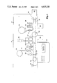
- FIG. 1 is a flow chart showing the assembly steps carried out by the method and apparatus of the present invention
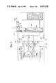
- FIGS. 2 and 3 are detailed schematic drawings showing the components of the assembly machine of the present invention.
- FIG. 4 is a side view of a lead feed machine used in the assembly machine shown in FIG. 2;
- FIG. 5 is a cross-sectional view taken along lines 5--5 of FIG. 4;
- FIG. 6 is a top plane view of a plunger and lead to spring assembly machine shown in FIG. 2.
- the method and apparatus for assembling an automatic and disposable pencil is described briefly by the flow chart of FIG. 1, wherein the various parts that comprise the automatic pencil are shown.
- the parts include a barrel 2 that receives a spring 4 whose helically wound coils form a tube into which is inserted a piece of lead 6 to which is attached, as by a press fit, a lead plunger 8.
- the plumger 8 includes tabs 9 which extend at right angles to engage the helical coils of spring 4.
- the tabs 9 also engage splines, not shown, in the barrel 2 to prevent the rotation of the plunger.
- a barrel tip 10 is first pressed onto closely wound coils 11 at the end of the spring 4. Thereafter, the barrel tip 10 is pressed into the barrel 2 so that a shoulder 12 on the tip 10 prevents its removal while permitting rotation of the tip.
- the flow chart of FIG. 1 also illustrates the order of the steps for assembling the pencil.
- the first step of the assembly process is to place the spring 4 and the barrel 2 respectively upon a first and second moving chain conveyor.
- the lead 6 is taken from an automatic feeder where it is combined with the lead plunger 8 by pressing the plunger onto one end of the lead 6.
- the piece of lead 6 and lead plunger 8 are then inserted into spring 4 by a simple tapping action.
- the subassembly of the spring, lead, and plunger is transferred from the first chain conveyor to the second chain conveyor where the subassembly is inserted into the barrel 2.
- the barrel is then rotated 180 degrees and the spring is partially removed from the barrel.
- the tip 10 is next inserted, as by a press fit, onto the closely wound coils 11 of spring 4.
- the tip 10 is inserted into the barrel 2 and retained therein by a press fit.
- Assembly of the eraser 13 is accomplished by again rotating the barrel 2 180 degrees and pressing the eraser 13 into barrel 2.
- a final step secures the eraser 13 to barrel 2 by staking.
- FIGS. 2 and 3 An assembly machine 14 which embodies the present invention is shown in greater detail in FIGS. 2 and 3 which may be joined end to end to show the complete machine. While assembly machines are generally known, the present invention is believed to be the first machine for assembling an automatic and disposable pencil.
- a first and second chain conveyor 15 and 16 are driven from left to right by motors, not shown. These same motors drive a cam shaft to which is attached several cams for driving each subassembly station in synchronous motion such that the chain conveyors 15 and 16 move one inch at a time.
- first and second chain conveyors 15 and 16 are supported on a long, rectangularly-shaped table 17.
- the table 17 also supports sprockets 18 which drive, and are driven by, the first and second chain conveyors 15 and 16.
- a spring feed assembly 19 which includes a feedbox 20 into which the springs 4 may be placed. When placed in the feedbox 20, the springs 4 have closely wound coils 11 on each end to prevent tangling.
- the springs 14 are removed from the feedbox 20 by a continually moving conveyor which consists of a plurality of platens 21 with grooves therein for receiving each individual spring.
- the spring feed assembly 19 is described in greater detail in the co-pending patent application referred to hereinabove under the "Summary Of The Invention.”
- the spring feed assembly 19 cascades the springs 4 down a slot which, under the control of a cam mechanism, not shown, distributes the springs one at a time onto the first chain conveyor 15.
- the spring feed slot includes a high and low level sensor, such as a photocell. The activation of the low level sensor stops the assembly machine 14 and activates a message displayed on a control console 22, FIG. 3.
- the pencil barrels 2 are loaded into a barrel loader 23 that comprises a large circular vibrating tray which moves the barrels in an outward and counterclockwise direction into a series of grooves where they are permitted to fall down a vertical slide 24.
- the barrels 2 are released one at a time from slide 24 to a barrel feed 25 and urged horizontally toward the second chain conveyor 16 by a reciprocating, cam driven plunger 26.
- the barrels then drop one at a time, under the control of a release 27, onto the second conveyor 16 where they are carried from left to right.
- a barrel detector 28 includes a cam-operated plunger 29 which is inserted into each barrel. The diameter of the plunger is such that it will move freely into the larger end of barrel 2 next to the clip but will not move into the smaller, opposite end thereof.
- a spring-loaded switch on the back of the plunger 29 opens when the plunger encounters the smaller end of barrel 2.
- a barrel orientation station 30 is activated to rotate the barrel 180 degrees so that the larger internal diameter thereof faces the first conveyor 15.
- the barrel orientation is accomplished by a pair of plungers that close about the barrel 2, raise the barrel from the conveyor 16, rotate 180 degrees, and return the barrel to the conveyor.
- the spring 4 is provided with closely wound coils 11 on either end while handled by the spring feed assembly 19. The reason for this is to prevent the springs 4 from tangling with one another.
- one end 11 of the spring 4 is sheared to cut the spring to the desired length and to provide an open, helical spring which receives the lead 6 and lead plunger 8.
- a lead feed machine 32 receives a supply of lead pieces 6 at a feedbox 33 which are withdrawn by drive and driven wheels 34. Wheels 34 drive a pair of notched chains 35 which carry the lead 6 to a vertical slot 36 where the lead is stacked in a column for the next step of the assembly. Each lead is removed from the slot 36 by a horizontally reciprocating cam that advances the lead to the next station where it receives the lead plunger 8, see FIGS. 4 and 5.
- the advantage of the pair of chains 35 in the lead feed machine 32 is that short or broken leads 6 will fall through the conveyor established thereby for sorting the unsuitable leads from the useful ones.
- the lead plungers 8 are placed within a hopper 37 which, like the barrel loader 23, comprises a vibrating tray that urges the plungers 8 to the outer periphery and into a counterclockwise direction where they are assembled in a vertical orientation within a horizontal channel 38.
- a plunger-to-lead assembly machine 39 grasps each vertical plunger, rotates the plunger 90 degrees, and moves the plunger forward where it is pressed upon one end of the lead 6.
- a reciprocating cam associated with the lead feed machine 32 (FIG. 4) advances the lead and plunger through three-steps in synchronization with the conveyor 15.
- the plunger-to-lead machine 39 moves the lead and plunger toward, and into, the spring 4 upon conveyor 15.
- a plunger and lead to spring assembly station 40 comprising a three-stage assemblier, takes over to tap the lead and plunger toward the spring.
- Station 40 is described in greater detail below regard to FIG. 6. It has been found that the spiral of the helically-wound spring 4 provides a sufficient inclined plane to permit the plunger 8 to be wound into the coils with nothing more than the tapping action of the assembly machine 40.
- an inspection is made for broken lead by lifting the assembled lead, plunger and spring by the lead tip. If the assembly does not lift free of a sensor, not shown, the assembly machine 14 notes the presence of a broken lead.
- the next stage is a two-step transfer of the lead, plunger and spring from the first conveyor 15 to the second conveyor 16.
- This is done by an assembler 42, which inserts the spring into the larger end of the barrel 2 as it lifts the spring from the first conveyor 15.
- the lead, plunger and spring subassembly is inserted into the splines, not shown, of barrel 2 by a six-stage pneumatic jet assembly 44, which blows the lead, plunger and spring subassembly into the barrel 2.
- an inspection station 45 inserts a rod into the barrel to check if the lead, plunger and spring subassembly is properly in the barrel 2.
- the barrel is ejected by an ejector 46 into a bin 47 where the barrel may be reclaimed.
- the reclaiming of the pencil lead and assembled plunger may require more manual effort than it is worth.
- the spring may not be reclaimed as one end thereof was sheared off at station 31.
- the next step within the assembly machine is to hot stamp the barrel 2 at station 48 with an appropriate trademark, logo, or the like.
- the barrel is oriented by an indexing clamp that rises from table 17 and grips the barrel to orient the clip in a vertical position. This permits the trademark, logo, or the like to be positioned along the barrel in parallel orientation with the clip.
- FIG. 3 The remaining portion of the assembly machine is shown in FIG. 3 wherein the table 17 supports only the second chain conveyor 16 and its driven sprocket 18.
- the barrel 2 was transported across the conveyor 16 with its larger internal diameter and clip facing the first conveyor 15. After the hot stamping process at station 48, the barrel is rotated 180 degrees by a barrel orientation device 50 to expose the smaller end of the barrel 2 to the assembly stations.
- the spring 4 is extended from barrel 2 by a spring advance station 52 that includes a plunger 53 which is inserted into the larger internal diameter of the barrel 2 to push the spring 4 from the barrel toward station 52.
- This step prepares the spring 4 for reception of the barrel tip 10 which is placed within a barrel tip feed tray 54 that comprises a vibrating tray which urges the tips to the outer edge of the tray and into a clockwise direction for passage into a tip-bearing channel 55 where the tips 10 are dropped one at a time down a vertical channel.
- a press 56 grips the spring 4 and moves the tip 10 into engagement with the closely wound coils 11 on the spring end.
- the chain conveyor 16 moves the partially assembled pencel 2 to the next station, the same press actuates a second surface 58 which presses the tip 10 firmly against spring 4.
- the barrel tip 10 After the barrel tip 10 has been assembled to the spring 4, the barrel tip is assembled to the barrel 2 at the next station where a first plunger surface 60 engages the outer end of tip 10 against the smaller internal diameter of barrel 2. At station 62, the tip 10 is pressed all the way into barrel 2 so that shoulder 12 of the tip 10 passes beyond an internal shoulder, not shown, within barrel 2. The two shoulders retain the barrel tip 10 within the barrel 2 while permitting the rotation of the tip.
- a servo motor 63 having a shaft 64 with a conically-shaped, longitudinal aperture in its end engages the barrel tip 10 to rotate the tip and extend the lead. The presence of the lead actuates a switch for sensing the existence thereof.
- a second servo motor 65 engages the tip 10 in a similar manner to return the lead to its desired position.
- the two motors 63 and 65 are mounted upon a platform which is moved forward and back by a suitable cam-actuated device 66 to engage and disengage tip 10. If the switch in shaft 64 sensed the absence of a lead, an ejector 67 ejects that pencil from the chain conveyor 16 into a second bin 68.
- the eraser assembly 70 includes a vibrating tray that causes the erasers 13 to pass into a channel 71 which stacks the erasers in a vertical column.
- the erasers are then dropped one at a time into a press 72 where they are seated into the barrel 2.
- a similar press 73 moves a sensing rod 74 against the eraser to check for the presence or absence thereof.
- a switch is activated which causes an ejection lever 75 at the next station to eject the pencil into a third bin 76.
- the final step of the assembly process is accomplished by station 78 which stakes the eraser 13 by piercing the end of barrel 2 for displacing the barrel material into the eraser to retain the eraser therein.
- station 78 which stakes the eraser 13 by piercing the end of barrel 2 for displacing the barrel material into the eraser to retain the eraser therein.
- the assembly of the automatic and disposable pencil thus completed, the assembled pencil is collected within a bin 80 for packaging and shipment.
- FIGS. 4 and 5 the lead feed machine 32 and its camming action are shown in greater detail mounted on a frame 84.
- the lead slot 36 is shown receiving the lead 6 carried to the slot by chain 35.
- a pivoted arm 86 that pivots about a pin 88 mounted in a slidable frame 90 which reciprocates to the right and left in FIGS. 4 and 5.
- FIG. 5 which is a cross-sectional view taken along line 5--5 of FIG. 4, that arm 86 is two arms having weights 92 attached to the left-hand ends thereof. Arms 86 have a pair of notches 94 that are normally aligned under the slot 36.
- the notch 94 moves one piece of lead 6 within it.
- a camming surface 96 on arms 86 strikes a second cam surface 98 on a fixed block 100 to raise the arms and notch 94 for lifting the lead 6 over a cam surface 102 on the moving frame 90.
- Arms 86 move tha lead forward 11/2 inches where the plunger to lead assembly machine 39 inserts the plunger 8, as by a press fit, to one end of the lead 6. Thereafter, the lead is retracted 1/4 inch to grooves 104 in cam surface 102.
- a second pair of pivoting arms 106 force the lead into grooves 104. As the arms 86 recycle, they pick up a second piece of lead to start the process again.
- the lead within the groove 104 moves forward 11/2 inches and comes to rest just over a lifting cam 108 slidably mounted to the frame 84.
- the slide mounting permits an up-down or vertical motion under the urging of a lifter 110.
- the lifter 108 is provided with a groove 112 having a larger width at its lower surface than its upper surface with a taper at its mid-section to guide the lead 6 in an upward direction.
- a three-finger, cam operated plunger to spring assembler 39 moves forward with its shortest finger engaging the lead and plunger within groove 112 to move the lead and plunger in the upward direction (FIG. 5).
- the lead 4 also enters the coils of a spring 4 carried by the first conveyor chain 15.
- the conveyor chain carries the spring with its partially inserted lead and plunger to the next groove 118 in block 116.
- the second longest finger from the cam operated plunger to lead assembler 39 pushes the lead one step further.
- the chain moves the spring and the partially inserted lead and plunger to a final groove 120 where the assembler 39 again pushes the lead and plunger yet further into a spring 4.
- FIG. 6 the details of the plunger and lead to spring assembly machine 40 are shown.
- the machine relies upon the configuration of the spring itself to form part of the operating machine. That is, the machine 40 consists of a pair of blocks 124, only one of which is shown in FIG. 6. These blocks mount three spring-loaded rods 126 within suitable bushings 128. As a cam moves the rods 126 forward, they contact the plunger 8 with a spring action from springs 129 that softly taps the plunger. After each tap, the tabs 9 on plunger 8 engage the helical coil of the spring 4 and turn on the inclined plane form therein. The subsequent tapping causes the tabs to turn for inserting the plunger 8 further into the coils of the spring 4. It has been found that one or two stations may be all that is necessary to tap the plunger 8 into the coils. However, the preferred embodiment incorporates three stations to assure that such insertion is complete, as shown in the far right-hand portion of FIG. 6.
- the assembly machine 14 has been designed to turn out assembled pencils at a rate of 60 per minute. While the assembly machine has been described with some specificity, i.e., moving left-to-right, it will be understood that the machine can also move right-to-left and that the present invention should be limited only by the appended claims.
Abstract
Description
Claims (24)
Priority Applications (1)
| Application Number | Priority Date | Filing Date | Title |
|---|---|---|---|
| US06/683,913 US4635338A (en) | 1984-12-18 | 1984-12-18 | Method and apparatus for assembling an automatic and disposable pencil |
Applications Claiming Priority (1)
| Application Number | Priority Date | Filing Date | Title |
|---|---|---|---|
| US06/683,913 US4635338A (en) | 1984-12-18 | 1984-12-18 | Method and apparatus for assembling an automatic and disposable pencil |
Publications (1)
| Publication Number | Publication Date |
|---|---|
| US4635338A true US4635338A (en) | 1987-01-13 |
Family
ID=24745983
Family Applications (1)
| Application Number | Title | Priority Date | Filing Date |
|---|---|---|---|
| US06/683,913 Expired - Lifetime US4635338A (en) | 1984-12-18 | 1984-12-18 | Method and apparatus for assembling an automatic and disposable pencil |
Country Status (1)
| Country | Link |
|---|---|
| US (1) | US4635338A (en) |
Cited By (15)
| Publication number | Priority date | Publication date | Assignee | Title |
|---|---|---|---|---|
| FR2723034A1 (en) * | 1994-07-26 | 1996-02-02 | Cross Co At | FOUR-BALL BALLPOINT MECHANISM |
| US5806164A (en) * | 1995-06-22 | 1998-09-15 | Wilks; Steven L. | Method for disassembling a writing instrument |
| WO2003026902A1 (en) * | 2001-09-25 | 2003-04-03 | Bic Corporation | Easily assembled grip element |
| US20030133143A1 (en) * | 2002-01-17 | 2003-07-17 | Cross Match Technology, Inc. | Biometric imaging system and method |
| US20060162814A1 (en) * | 2004-12-21 | 2006-07-27 | Kronotec Ag | Device for inserting connecting elements in the end faces and/or longitudinal sides of technical wood products |
| US20130168202A1 (en) * | 2011-12-29 | 2013-07-04 | Beifa Group Co., Ltd. | Fountain-pen automatic assembly line |
| US20130167371A1 (en) * | 2011-12-29 | 2013-07-04 | Beifa Group Co., Ltd. | Flat-pen automatic assembly line |
| CN103862280A (en) * | 2014-02-08 | 2014-06-18 | 温州职业技术学院 | Automatic eyebrow pencil assembly line equipment and assembly process flow thereof |
| US8917297B2 (en) | 2011-12-29 | 2014-12-23 | Beifa Group Co., Ltd. | Pen-barrel heat transferring device |
| US9221560B2 (en) | 2011-12-29 | 2015-12-29 | Beifa Group Co., Ltd. | Vibrating device for uniform filling of granular ornaments |
| CN107363498A (en) * | 2017-07-26 | 2017-11-21 | 威海科莱默自动化设备有限公司 | A kind of automatic Pencil-inserting machine and its automatically a slotting method |
| US20180304671A1 (en) * | 2017-04-19 | 2018-10-25 | Yu-Chun Liu | Pen assembly press and lever thereof |
| CN109501488A (en) * | 2018-10-17 | 2019-03-22 | 温州西通文具有限公司 | A kind of combination discharge system of the pen core combination machine of propelling pencil |
| CN113844197A (en) * | 2021-11-10 | 2021-12-28 | 上饶市杜克文具有限公司 | Self-service equipment system pen equipment |
| CN113844196A (en) * | 2021-11-10 | 2021-12-28 | 江西省永智制笔有限公司 | Inserting device for pen point and pen holder |
Citations (9)
| Publication number | Priority date | Publication date | Assignee | Title |
|---|---|---|---|---|
| US1539468A (en) * | 1922-08-08 | 1925-05-26 | William E Cook | Pencil |
| US1627602A (en) * | 1921-04-29 | 1927-05-10 | Byron B Goldsmith | Mechanical pencil |
| DE454572C (en) * | 1925-03-10 | 1928-01-12 | Felss Geb | Pen |
| US2046582A (en) * | 1934-05-26 | 1936-07-07 | Melrose Products Co Inc | Mechanical pencil |
| US2087519A (en) * | 1936-06-27 | 1937-07-20 | Melrose Products Co Inc | Mechanical pencil |
| US2356509A (en) * | 1943-09-27 | 1944-08-22 | Autopoint Co | Mechanical pencil and method of making same |
| US2532791A (en) * | 1946-10-18 | 1950-12-05 | Scripto Inc | Mechanical pencil with screw feed and hopper type magazine |
| US3097628A (en) * | 1960-07-07 | 1963-07-16 | Dur O Lite Pencil Company | Mechanical pencil |
| US4259780A (en) * | 1979-04-09 | 1981-04-07 | Genevieve I. Hanscom | Parts assembler for ballpoint pens |
-
1984
- 1984-12-18 US US06/683,913 patent/US4635338A/en not_active Expired - Lifetime
Patent Citations (9)
| Publication number | Priority date | Publication date | Assignee | Title |
|---|---|---|---|---|
| US1627602A (en) * | 1921-04-29 | 1927-05-10 | Byron B Goldsmith | Mechanical pencil |
| US1539468A (en) * | 1922-08-08 | 1925-05-26 | William E Cook | Pencil |
| DE454572C (en) * | 1925-03-10 | 1928-01-12 | Felss Geb | Pen |
| US2046582A (en) * | 1934-05-26 | 1936-07-07 | Melrose Products Co Inc | Mechanical pencil |
| US2087519A (en) * | 1936-06-27 | 1937-07-20 | Melrose Products Co Inc | Mechanical pencil |
| US2356509A (en) * | 1943-09-27 | 1944-08-22 | Autopoint Co | Mechanical pencil and method of making same |
| US2532791A (en) * | 1946-10-18 | 1950-12-05 | Scripto Inc | Mechanical pencil with screw feed and hopper type magazine |
| US3097628A (en) * | 1960-07-07 | 1963-07-16 | Dur O Lite Pencil Company | Mechanical pencil |
| US4259780A (en) * | 1979-04-09 | 1981-04-07 | Genevieve I. Hanscom | Parts assembler for ballpoint pens |
Cited By (27)
| Publication number | Priority date | Publication date | Assignee | Title |
|---|---|---|---|---|
| FR2723034A1 (en) * | 1994-07-26 | 1996-02-02 | Cross Co At | FOUR-BALL BALLPOINT MECHANISM |
| ES2129288A1 (en) * | 1994-07-26 | 1999-06-01 | Cross Co A T | Four part ball point pen mechanism |
| US5806164A (en) * | 1995-06-22 | 1998-09-15 | Wilks; Steven L. | Method for disassembling a writing instrument |
| WO2003026902A1 (en) * | 2001-09-25 | 2003-04-03 | Bic Corporation | Easily assembled grip element |
| AU2002213056B2 (en) * | 2001-09-25 | 2007-05-31 | Bic Corporation | Easily assembled grip element |
| US20030133143A1 (en) * | 2002-01-17 | 2003-07-17 | Cross Match Technology, Inc. | Biometric imaging system and method |
| US20030142856A1 (en) * | 2002-01-17 | 2003-07-31 | Cross Match Technology, Inc. | Biometric imaging system and method |
| US20050180619A1 (en) * | 2002-01-17 | 2005-08-18 | Cross Match Technologies, Inc. | Biometric imaging system and method |
| US8073209B2 (en) | 2002-01-17 | 2011-12-06 | Cross Match Technologies, Inc | Biometric imaging system and method |
| US7203344B2 (en) * | 2002-01-17 | 2007-04-10 | Cross Match Technologies, Inc. | Biometric imaging system and method |
| US7308122B2 (en) | 2002-01-17 | 2007-12-11 | Cross Match Technologies, Inc. | Biometric imaging system and method |
| US20100206435A1 (en) * | 2004-12-21 | 2010-08-19 | Kronotec Ag | Method of inserting connecting elements in the end faces and/or longitudinal sides of technical wood products |
| US7730601B2 (en) * | 2004-12-21 | 2010-06-08 | Kronotec, Ag | Device for inserting connecting elements in the end faces and/or longitudinal sides of technical wood products |
| US7958618B2 (en) | 2004-12-21 | 2011-06-14 | Kronotec Ag | Method of inserting connecting elements in the end faces and/or longitudinal sides of technical wood products |
| US20060162814A1 (en) * | 2004-12-21 | 2006-07-27 | Kronotec Ag | Device for inserting connecting elements in the end faces and/or longitudinal sides of technical wood products |
| US8917297B2 (en) | 2011-12-29 | 2014-12-23 | Beifa Group Co., Ltd. | Pen-barrel heat transferring device |
| US20130167371A1 (en) * | 2011-12-29 | 2013-07-04 | Beifa Group Co., Ltd. | Flat-pen automatic assembly line |
| US20130168202A1 (en) * | 2011-12-29 | 2013-07-04 | Beifa Group Co., Ltd. | Fountain-pen automatic assembly line |
| US9221560B2 (en) | 2011-12-29 | 2015-12-29 | Beifa Group Co., Ltd. | Vibrating device for uniform filling of granular ornaments |
| US9321296B2 (en) * | 2011-12-29 | 2016-04-26 | Beifa Group Co., Ltd. | Flat-pen automatic assembly line |
| CN103862280A (en) * | 2014-02-08 | 2014-06-18 | 温州职业技术学院 | Automatic eyebrow pencil assembly line equipment and assembly process flow thereof |
| CN103862280B (en) * | 2014-02-08 | 2016-01-27 | 温州职业技术学院 | Eyebrow pencil automatic assembly line equipment and assemble flow thereof |
| US20180304671A1 (en) * | 2017-04-19 | 2018-10-25 | Yu-Chun Liu | Pen assembly press and lever thereof |
| CN107363498A (en) * | 2017-07-26 | 2017-11-21 | 威海科莱默自动化设备有限公司 | A kind of automatic Pencil-inserting machine and its automatically a slotting method |
| CN109501488A (en) * | 2018-10-17 | 2019-03-22 | 温州西通文具有限公司 | A kind of combination discharge system of the pen core combination machine of propelling pencil |
| CN113844197A (en) * | 2021-11-10 | 2021-12-28 | 上饶市杜克文具有限公司 | Self-service equipment system pen equipment |
| CN113844196A (en) * | 2021-11-10 | 2021-12-28 | 江西省永智制笔有限公司 | Inserting device for pen point and pen holder |
Similar Documents
| Publication | Publication Date | Title |
|---|---|---|
| US4635338A (en) | Method and apparatus for assembling an automatic and disposable pencil | |
| US4054988A (en) | Machine for processing and securing parallel lead electronic circuit elements to a printed circuit board | |
| US4720228A (en) | Automatic parts handling apparatus | |
| CN107310939B (en) | Full-automatic battery piece sorting machine | |
| EP0587248A1 (en) | Loading device for sequential loading of bars in machine tools | |
| US4500246A (en) | Indexed feed of electronic component supply tubes | |
| NL8103407A (en) | CARRIER FOR RIVETS, METHOD AND APPARATUS FOR MANUFACTURING SUCH CARRIER. | |
| US4245385A (en) | Radial lead component insertion machine | |
| JPH10296576A (en) | Bar material feeding device | |
| JPH0768413A (en) | Feed/fetch device for blind broaching | |
| EP0356654A1 (en) | Device for supplying (package) blanks to a packaging machine | |
| US4263708A (en) | Machine for automatically inserting parallel lead electronic components into a printed circuit board | |
| US5510081A (en) | Test sampling apparatus | |
| GB2100626A (en) | Component applying machine | |
| US3150390A (en) | Apparatus for trimming sequentially the opposite ends of an elongated workpiece | |
| US3584761A (en) | Workpiece feeding apparatus with reciprocable shuttle | |
| US5165837A (en) | Apparatus for feeding articles from tube magazines | |
| US3576063A (en) | Bobbin lugger and method | |
| JPS60120600A (en) | Inserting device | |
| US4409733A (en) | Means and method for processing integrated circuit element | |
| US5108245A (en) | Device for the axial transport of elongated objects | |
| US4817491A (en) | Apparatus for a firearm ammunition hand loader | |
| US3062390A (en) | Wire handling apparatus | |
| US4805498A (en) | Apparatus for cutting adhesive tape roll stocks | |
| CN114210885A (en) | Heat pipe processing machine |
Legal Events
| Date | Code | Title | Description |
|---|---|---|---|
| AS | Assignment |
Owner name: GILLETTE COMPANY,THE, PRUDETIAL TOWER BUILDING,BOS Free format text: ASSIGNMENT OF ASSIGNORS INTEREST.;ASSIGNOR:WALSH, WILLIAM H.;REEL/FRAME:004369/0985 Effective date: 19841217 |
|
| STCF | Information on status: patent grant |
Free format text: PATENTED CASE |
|
| FEPP | Fee payment procedure |
Free format text: PAYOR NUMBER ASSIGNED (ORIGINAL EVENT CODE: ASPN); ENTITY STATUS OF PATENT OWNER: LARGE ENTITY |
|
| FPAY | Fee payment |
Year of fee payment: 4 |
|
| SULP | Surcharge for late payment | ||
| FEPP | Fee payment procedure |
Free format text: PAYER NUMBER DE-ASSIGNED (ORIGINAL EVENT CODE: RMPN); ENTITY STATUS OF PATENT OWNER: LARGE ENTITY Free format text: PAYOR NUMBER ASSIGNED (ORIGINAL EVENT CODE: ASPN); ENTITY STATUS OF PATENT OWNER: LARGE ENTITY |
|
| FPAY | Fee payment |
Year of fee payment: 8 |
|
| FPAY | Fee payment |
Year of fee payment: 12 |
|
| AS | Assignment |
Owner name: BEROL CORPORATION, ILLINOIS Free format text: ASSIGNMENT OF ASSIGNORS INTEREST;ASSIGNOR:THE GILLETTE COMPANY;REEL/FRAME:011987/0649 Effective date: 20001220 |