US4641322A - System for carrying out spread spectrum communication through an electric power line - Google Patents
System for carrying out spread spectrum communication through an electric power line Download PDFInfo
- Publication number
- US4641322A US4641322A US06/662,111 US66211184A US4641322A US 4641322 A US4641322 A US 4641322A US 66211184 A US66211184 A US 66211184A US 4641322 A US4641322 A US 4641322A
- Authority
- US
- United States
- Prior art keywords
- signal
- electric power
- pseudorandom code
- power line
- station
- Prior art date
- Legal status (The legal status is an assumption and is not a legal conclusion. Google has not performed a legal analysis and makes no representation as to the accuracy of the status listed.)
- Expired - Lifetime
Links
Images


Classifications
-
- H—ELECTRICITY
- H04—ELECTRIC COMMUNICATION TECHNIQUE
- H04B—TRANSMISSION
- H04B1/00—Details of transmission systems, not covered by a single one of groups H04B3/00 - H04B13/00; Details of transmission systems not characterised by the medium used for transmission
- H04B1/69—Spread spectrum techniques
- H04B1/707—Spread spectrum techniques using direct sequence modulation
-
- H—ELECTRICITY
- H04—ELECTRIC COMMUNICATION TECHNIQUE
- H04B—TRANSMISSION
- H04B3/00—Line transmission systems
- H04B3/54—Systems for transmission via power distribution lines
- H04B3/542—Systems for transmission via power distribution lines the information being in digital form
Definitions
- This invention relates to a system for use in carrying out communication between a plurality of stations through an electric power line, such as a power transmission line, a distribution line, or the like.
- an electric power line of the type described serves to deliver electric power of a commercial frequency to a wide variety of loads connected thereto.
- the electric power falls within a commercial frequency band.
- Various attempts have been made to transmit an information signal between stations through such an electric power line.
- the electric power line is put in bad circumstances for transmission of the information signal because noises, such as a corona noise and the like, or undesired signals, such as harmonic waves of a commercial frequency, inevitably appear on the electric power line.
- a variation of the loads gives rise to a variation of a noise characteristic and a transmission characteristic of the electric power line.
- the characteristics of the electric power line are widely variable with time.
- transmission of the information signal should not adversely affect any other systems or devices coupled to the electric power line.
- a limited electric power is therefore shared with transmission of the information signal and degrades a quality of the transmission.
- a conventional system which comprises a transmitter for carrying out FSK modulation to transmit a modulated signal conveying an information signal to an A.C. line, namely, an electric power line and a receiver for demodulating the modulated signal by the use of a phase lock loop.
- the modulated signal falls within a specific frequency band which is different from that of the electric power.
- Both of the transmitter and the receiver might be incorporated into a station coupled to the electric power line.
- a plurality of stations may be connected to the electric power line to carry out communication therebetween.
- the modulated signal is undesiredly deteriorated by noises because the noises may fall within the specific frequency band.
- the characteristics may vary in the specific frequency band.
- a system to which this invention is applicable is for use in conveying a transmission signal from a transmission station to a reception station through an electric power line for electric power of a commercial frequency following within a first frequency region.
- the transmission station comprises modulation means responsive to the transmission signal for carrying out spread spectrum modulation of the transmission signal to produce a modulated signal which is subjected to the spread spectrum modulation and which is dispersed in a second frequency region different from the first frequency region and sending means coupled to the electric power line and the modulation means for sending the modulated signal to the electric power line.
- the reception station comprises extracting means coupled to the electric power line for extracting the modulated signal from the second frequency region to produce an extracted signal, demodulation means coupled to the extracting means for demodulating the extracted signal into a demodulated signal carrying the information signal, and means for deriving the transmission signal from the demodulated signal.
- FIG. 1 exemplifies a transmission characteristic on an electric power line
- FIG. 2 exemplifies a modulation spectrum of a modulated signal transmitted to the electric power line
- FIG. 3 exemplifies a demodulation spectrum of a demodulated signal sent through the electric power line having the transmission characteristic shown in FIG. 1;
- FIGS. 4(a) through 4(c) are time charts for use in describing a principle of this invention.
- FIGS. 5(a) through 5(d) exemplify power spectra corresponding to FIGS. 4(a) through 4(c), respectively;
- FIG. 6 is a block diagram of a communication system according to each of first through third embodiments of this invention.
- FIG. 7 is a block diagram of a station for use in the communication system according to the first embodiment of this invention.
- FIG. 8 is a block diagram of a station for use in the communication system according to the second embodiment of this invention.
- FIG. 9 is a block diagram of a receiver synchronization circuit for use in the station illustrated in FIG. 8;
- FIG. 10 is a block diagram of a station for use in the communication system according to the third embodiment of this invention.
- FIG. 11 is a block diagram of a communication system according to a fourth and a fifth embodiment of this invention.
- FIG. 12 is a block diagram of a polling station for use in the communication system illustrated in FIG. 11;
- FIG. 13 is a block diagram of a block station for use in combination with the polling station illustrated in FIG. 12;
- FIG. 14 is a block diagram of a polling station for use in a communication system according to the fifth embodiment of this invention.
- FIG. 15 is a block diagram of a local station for use in combination with the polling station illustrated in FIG. 14;
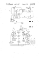
- FIG. 16 is a block diagram of a power control circuit which is applicable to each of the embodiments.
- FIG. 17 is a block diagram of another control circuit for carrying out operation similar to that illustrated in FIG. 16;
- FIG. 18 is a circuit diagram of a coupler for use in each embodiment
- FIG. 19 is a block diagram of an automatic gain control circuit which is applicable to each embodiment
- FIG. 20 is a block diagram of a station for use in a communication system according to a modification of this invention.
- FIG. 21 is a block diagram of a receiver synchronization circuit which is applicable to each embodiment.
- FIGS. 1 through 3 description will be made as regards a conventional method of carrying out amplitude modulation, phase modulation, frequency modulation, or any other modulation.
- an electric power line have a transmission characteristic H(f) having a null point or zone at a high frequency f 1 .
- the high frequency f 1 is different from a commercial frequency of electric power delivered to various loads connected to the electric power line.
- a frequency band for the commercial frequency is herein called a first frequency band.
- the modulation be carried out by the use of a central frequency equal to the frequency f 1 to transmit a modulated signal to the electric power line.
- a modulated signal exhibits a modulation spectrum M(f) locally laid in a frequency band adjacent to the central frequency.
- a demodulated signal When the modulated signal is transmitted through the electric power line having the transmission characteristic shown in FIG. 1 and is subjected to demodulation, a demodulated signal has a demodulation spectrum S(f) depicted in FIG. 3.
- the demodulation spectrum S(f) is seriously reduced or deteriorated in comparison with the modulation spectrum M(f). Therefore, transmission performance is degraded unfavorably.
- the transmission characteristic is variable with time.
- the null point irregularly moves with time. This widely varies electric power of the demodulated signal and makes it difficult to achieve stable communication.
- the conventional modulation method is not suitable for a transmission system which carries out transmission through an electric power line.
- a principle of this invention is to carry out spread spectrum communication through the electric power line.
- spread spectrum modulation and demodulation are carried out in a transmitter and a receiver, respectively.
- Such spread spectrum communication is usually used in a radio communication system because the spread spectrum communication is strong against fading, a local noise over a narrow band, and the like and has a high secrecy.
- the spread spectrum communication is scarcely applied to a wire communication system, such as an electric power line system.
- the spread spectrum communication will be described hereinunder. Let the information signal exhibit a waveform along an axis of time (t) as shown in FIG. 4(a) and a first power spectrum P(f) along an axis of frequency (f) as shown in FIG. 5(a).
- the information signal is a succession of data pulses produced at a data rate.
- a pseudorandom code sequence is produced in synchronism with a succession of clock pulses having a clock rate higher than the data clock rate and is repeated at a frame period equal to a reciprocal of the data rate.
- the frame period is determined by a code length of the pseudorandom code sequence.
- Such a pseudorandom code may be a maximum length code known in the art and has a second power spectrum P 2 (f) along an axis of frequency, as shown in FIG. 5(b).
- the second power spectrum P 2 (f) has a plurality of frequency components dispersed in a wide frequency band defined by the code length of the pseudorandom code sequence. More specifically, a maximum one of the frequency components is represented by f N , if the code length is specified by N.
- the pseudorandom code sequence is modulated by the information signal into a modulated signal as shown in FIG. 4(c) according to the spread spectrum modulation.
- the spread spectrum modulation is possible by a multiplier for calculating a product between the information signal and the pseudorandom code sequence.
- the modulated signal exhibits a modulation spectrum M(f) divisible into a plurality of partial spectra depicted at M 1 through M N which are specified by main envelopes and are laid in the vicinity of the frequency components shown in FIG. 5(b), respectively.
- Each of the partial spectra M 1 through M N uniformly includes a signal component of the information signal distributed thereto in the manner known in the art.
- the modulation spectrum is distributed like a white noise to the wide frequency band proportional to the code length of the pseudorandom code sequence.
- the modulated signal be transmitted through the electric power line having the transmission characteristic H(f) shown in FIG. 1.
- the demodulated signal has a demodulation spectrum S(f) as shown at a real line in FIG. 5(a).
- the demodulation spectrum S(f) is hardly reduced despite the fact that the transmission characteristic has the null point at the frequency f 1 .
- the modulation spectrum M(f) is spread over the wide frequency band as exemplified in FIG. 5(c) and a reduction of electric power of the modulated signal is very small even when a null point or points locally appear on the electric power line. Accordingly, it is possible with this invention to realize communication which is strong against a selective jamming wave or noise. This means that the communication can be carried out with a high reliability and at a high speed.
- the pseudorandom code sequence takes a plurality of phases during the frame period and may be modified in phase into modified code sequences which can form different pseudorandom code sequences, respectively, in the manner which is also known in the art. Such modification is possible by indicating initial phases of the pseudorandom code sequences.
- a communication system comprises an electric power line 30 which may be either to power transmission line or a distribution cable.
- a plurality of stations are coupled to the electric power line 30, although only two stations are illustrated in FIG. 6 and will be referred to as first and second stations denoted by 31 and 32, respectively.
- each of the first and second stations 31 and 32 carries out both of transmission and reception through the electric power line 30.
- the first and second stations 31 and 32 can optionally be connected to or disconnected from the electric power line 30 by receptacles (not shown). In other words, each station is not actively coupled to the electric power line 30 but is passively coupled to the line 30.
- station addresses are preassigned to the respective stations.
- a plurality of terminal units collectively denoted by 33 1 and 33 2 are connected to the first and second stations 31 and 32, respectively. From this fact, it is readily understood that communication is finally carried out between two of the terminal units 33 1 and 33 2 .
- Each of the terminal units 33 1 and 33 2 comprises an input and an output device. Despite the terminal units 33 1 and 33 2 , description will mainly be directed to communication between the first and second stations 31 and 32.
- each of the first and second stations 31 and 32 comprises a transmitter 36 and a receiver 37 for carrying out the transmission and reception, respectively, in the manner which will later be described more in detail.
- a coupler 39 is common to the transmitter 36 and the receiver 37 and operable as parts of the transmitter 36 and the receiver 37.
- the coupler 39 is coupled through the receptacle (not shown) to the electric power line 30.
- the coupler 39 is operable to deliver electric power PW of the commercial frequency to various electric devices (not shown).
- the transmitter 36 comprises a multiplexer 41 supplied with input signals from the input devices of the terminal units 33 (suffixes omitted).
- the input signals are multiplexed by the multiplexer 41 into a multiplexed signal and is sent to a transmitter multiplier 42.
- the multiplexed signal may be called an information signal IS conveying information.
- the information signal IS is transmitted from the first station 31 for reception by the second station 32.
- the first and second stations 31 and 32 may be referred to as an originating and a destination station, respectively.
- the destination address is specified by a transmission controller 43 which is operable in cooperation with the terminal units 33.
- the destination address is sent to a first pseudorandom noise (PN) generator 46.
- PN pseudorandom noise
- the first PN generator 46 may be a combination of flip flops and Exclusive OR gates in the manner well known in the art and can generate a plurality of pseudorandom code sequences which are equal in code length to one another and different in phase from one another, when initial phases of the respective pseudorandom code sequences are indicated, as suggested before.
- the plurality of pseudorandom code sequences are made to correspond to the respective station addresses and are used to specify the respective station addresses in the example being illustrated.
- Each of the pseudorandom code sequences PN may be called a pseudorandom noise sequence.
- the destination address indicated by the transmission controller 43 is given to the PN generator 46 as an initial phase signal indicative of one of the initial phases that specifies a selected one of the pseudorandom code sequences PN.
- the selected pseudorandom code sequence will be referred to as a modulation pseudorandom code sequence and is sent to the multiplier 42.
- the transmitter multiplier 42 carries out product modulation between the information signal IS and the selected pseudorandom code sequence PN to produce a product signal or modulated signal MD representative of a product therebetween.
- the product signal has a modulation spectrum spread over a wide frequency band as illustrated in FIG. 5(c). Accordingly, the product modulation may be called spread spectrum modulation.
- a combination of the transmitter multiplier 42 and the first PN generator 46 may be called a modulator 47.
- An adder 48 adds the modulated signal MD to a transmitter synchronization signal SYNC 1 to supply the coupler 39 with a sum signal representative of the sum through a transmitter amplifier 49.
- the transmitter synchronization signal SYNC 1 is produced in a manner to be described later and may be formed by an additional pseudorandom code sequence of a period which is equal to the pseudorandom code sequences generated by the first PN generator 46 and which is different from all of the pseudorandom code sequences.
- the transmitter synchronization signal SYNC 1 serves to define each frame of the selected or modulation pseudorandom code sequence.
- the coupler 39 sends the sum signal to the electric power line 30 as a transmitter output signal after it attenuates a low frequency component of the sum signal falling within the first frequency band for the commercial frequency.
- the transmitter output signal is not superposed in frequency on the electric power signal PW of the commercial frequency and is widely dispersed in the second frequency band.
- the adder 48, the transmitter amplifier 49, and the part of the coupler 39 may be called a sending circuit for sending the modulated signal to the electric power line 30.
- the transmitter output signal arrives at the second station 32 as a receiver input signal through the electric power line 30 and is extracted by the coupler 39 from the electric power signal PW.
- the receiver input signal is supplied through a receiver amplifier 51 to an automatic gain control (AGC) circuit 52.
- AGC automatic gain control
- the AGC circuit 52 has a dynamic range enough to compensate for a variation of a dead loss on the electric power line 30 and produces a gain controlled signal GC having substantially constant electric power.
- the AGC circuit 52 will later be described as regards its operation and structure in detail.
- the gain controlled signal GC includes the transmitter synchronization signal SYNC 1 and the selected pseudorandom code sequence PN 1 modulated by the information signal IS, like the transmitter output signal.
- the gain controlled signal GC is delivered from the AGC circuit 52 to a receiver synchronization circuit 54 and a receiver multiplier 56.
- the receiver synchronization circuit 54 derives a clock signal and a frame signal from the gain controlled signal GC.
- the frame signal reproduces the frame specified by the transmitter synchronization signal SYNC 1 while the clock signal specifies clock components included in the gain controlled signal GC. Operation and structure will become clear later.
- the clock signal and the frame signal are supplied to a second pseudorandom noise (PN) generator 57.
- the second PN generator 57 is operable in response to an initial phase signal supplied from a receiver controller 59.
- the initial phase signal specifies an initial phase of a demodulation pseudorandom code sequence PD assigned to the second or destination station 32.
- the second pseudorandom noise generator 57 supplies the receiver multiplier 56 with the demodulation pseudorandom code sequence PD.
- the demodulation pseudorandom code sequence PD is assumed to be coincident with the modulation pseudorandom code sequence PN.
- the receiver multiplier 56 carries out product demodulation to demodulate the gain controlled signal GC into a demodulated signal DM.
- the demodulated signal DM is filtered through a low-pass filter 61 into a reproduction of the information signal IS.
- the reproduction of the information signal IS may be called a reception signal and is delivered through a demultiplexer 62 to a destination one of the terminal units 33 2 of the second station 32.
- a station is for use as each station of a communication system according to a second embodiment of this invention and comprises similar parts designated by like reference numerals and symbols.
- the illustrated station is assumed to be operable in cooperation with a single terminal unit 33 (FIG. 6).
- a preselected pseudorandom code sequence which has a predetermined phase is used in common to the plurality of stations as shown in FIG. 8. In other words, the preselected pseudorandom code sequence is kept unchanged in phase.
- a destination address is given to each station in the form of a destination address signal AD specifying a destination station assigned to a destination station.
- the destination address signal AD is produced by the terminal unit 33 and is followed by the information signal IS.
- the transmitter 36 is operable in relation to the receiver 37 in a manner to be described later. It suffices to say that the transmitter 36 is operated only when the electric power line 30 is not used by other stations than the illustrated station.
- the information signal IS be transmitted from the first station 31 to the second station 32, like in FIG. 7, and the illustrated station be at first used as the first station 31.
- a transmission request signal RQ of a logic "1" level is given prior to transmission of the information signal IS from the terminal unit 33 of the first station 31 to an AND gate 65 in a manner to be described later.
- the AND gate 65 is supplied with the logic "1" level and the logic "0" level when the electric power line 30 is being unused and used, respectively.
- the AND gate 65 delivers a logic "1" level signal to a modulator 47.
- the illustrated modulator 47 comprises a timer 66 in addition to the multiplier 42 and the first PN generator 46.
- the timer 66 is enabled or energized in response to the logic "1" level signal sent from the AND gate 65 and times or measures a predetermined duration T 0 .
- the AND gate 65 and the logic "1" level signal may be referred to as an energizing circuit and an energizing signal, respectively.
- the timer 66 supplies the first PN generator 46 and the terminal unit 33 with a start pulse ST indicative of a start of operation.
- the first PN generator 46 delivers the preselected pseudorandom code sequence denoted by PN' to the transmitter multiplier 42 in synchronism with a sequence of transmitter clock pulses CK 1 which is given from the transmitter controller 43, although not explicitly described in conjunction with FIG. 7.
- the terminal unit 33 supplies the transmitter multiplier 42 with the destination address signal AD followed by the information signal IS, as mentioned before.
- the preselected pseudorandom code sequence PN' is modulated by the destination address signal AD and by the information signal IS and sent as a modulated signal MD' to the adder 48.
- a synchronization signal generator denoted by 68 is coupled to the adder 48 to generate the transmitter synchronization signal SYNC 1 .
- the synchronization signal generator 68 is energized by the logic "1" level signal, namely, energizing signal and begins to produce the transmitter synchronization signal SYNC 1 . Consequently, the transmitter synchronization signal SYNC 1 precedes the modulated signal MD' by the predetermined duration T 0 . This means that the transmitter synchronization signal SYNC 1 alone appears the predetermined duration T 0 and thereafter the modulated signal MD' is superposed on the transmitter synchronization signal SYNC 1 .
- the sum signal between the transmitter synchronization signal SYNC 1 and the modulated signal MD' is sent as a transmitter output signal from the adder 48 through the transmitter amplifier 49 and the coupler 39 to the electric power line 30.
- the transmitter output signal mentioned above be received as a receiver input signal by the second station 32.
- the illustrated receiver 37 is assumed to be used in the second station 32 for brevity of description.
- the receiver input signal is extracted from the electric power signal PW by the coupler 39 to be sent through the receiver amplifier (not shown in this figure) to the AGC circuit 52.
- the gain controlled signal GC is delivered from the AGC circuit 52 to a receiver synchronization circuit 54'.
- the receiver synchronization circuit 54' is similar to the receiver synchronization circuit 54 illustrated in FIG. 7 except that an additional multiplier 71 and an additional low-pass filter 72 is used in the illustrated receiver synchronization circuit 54'. The remaining part forms a delay lock loop known in the art.
- the receiver synchronization circuit 54' comprises a local pseudorandom noise (PN) genrator 73 which is put into operation in synchronism with a sequence of receiver clocks CK 2 produced by a voltage controlled oscillator (VCO) 75.
- the local PN generator 73 generates a first local PN code sequence LO 1 identical with the transmitter synchronization signal SYNC 1 and a second local PN code sequence L0 2 delayed by two bits, namely, two clocks relative to the first local PN code sequence LO 1 .
- the illustrated local PN generator 73 also generates a third local PN code sequence L0 3 delayed by a single bit relative to the first local PN code sequence LO 1 .
- the first and the second local PN code sequences LO 1 and L0 2 are delivered to first and second multipliers 76 and 77, respectively, while the third local PN code sequence L0 3 is delivered to the additional multiplier 71.
- the first and the second multipliers 76 and 77 calculate first and second products between the gain controlled signal GC and the first local PN code sequence LO 1 and between the gain controlled signal GC and the second local PN code sequence LO 2 , respectively.
- each of the first and the second multipliers 76 and 77 calculate correlations between the gain controlled signal GC and each of the first and the second local PN code sequences LO 1 and L0 2 .
- a subtractor 79 subtracts the second product from the first product to supply a loop filter 81 with a difference signal representative of a difference between the first and the second products.
- the difference signal is sent in the form of a variable voltage to the voltage controlled oscillator 75.
- the voltage controlled oscillator 75 produces the receiver clock pulses CK 2 having a repetition frequency determined by the voltage of the difference signal.
- Synchronization is established when the difference between the first and the second products becomes equal to zero, as known in the art.
- This illustrated receiver synchronization circuit 54' is designed so that synchronization is established within the predetermined duration T 0 .
- the third local PN code sequence L0 3 is phase matched with the transmitter synchronization signal SYNC 1 conveyed by the gain controlled signal GC.
- the third local PN code sequence L0 3 is delivered to a frame synchronization circuit 83 for defining each frame of the gain controlled signal GC.
- a sequence of frame pulses FR is produced by the frame synchronization circuit 83 in response to the third local PN code sequence L0 3 and delivered to the second PN generator 57 (FIG. 8) together with the receiver clock pulses CK 2 .
- the additional multiplier 71 multiplies the third local PN code sequence L0 3 by the gain controlled signal GC to supply a third product to the additional low-pass filter 72.
- the third product specifies a correlation between the transmitter synchronization signal SYNC 1 and the third local PN code sequence L0 3 .
- the third product becomes large and small when the above-mentioned correlation is strong and weak, respectively.
- the strong correlation indicates presence of the transmitter synchronization signal SYNC 1 in the gain controlled signal GC while the weak correlation indicates absence of the transmitter synchronization signal SYNC 1 .
- the third product is produced through the additional low-pass filter 72 as a line status signal LS representative of a status of the electric power line 30.
- the line status signal LS takes a variable level in accordance with the third product.
- the modulated signal MD' After lapse of the predetermined duration T 0 , the modulated signal MD' also appears in superposition on the transmitter synchronization signal SYNC 1 as the gain controlled signal GC. However, the synchronization has already been established in the receiver synchronization circuit 54' when the modulated signal MD' is received. In this event, the modulated signal MD' becomes a high frequency noise and can be rejected by the additional low-pass filter 72. In order to enable the above-mentioned operation, the modulated signal MD' may be substantially orthogonal to the transmitter synchronization signal SYNC 1 .
- the frame pulses FR and the receiver clocks CK 2 are sent to a second PN generator 57 which is similar to that illustrated in FIG. 7.
- the second PN generator 57 supplies the receiver multiplier 56 with a demodulation pseudorandom code sequence PD' in synchronism with the frame pulses FR and the receiver clocks CK 2 .
- the demodulation pseudorandom code sequence PD' of each station is identical with the preselected pseudorandom code sequence PN' produced by the first PN generator 46 of each station because the preselected pseudorandom code sequence PN' is in common to all of the stations, as mentioned before.
- the receiver multiplier 56 demodulates the gain controlled signal GC into a demodulated signal DM with reference to the demodulation pseudorandom code sequence PD' in the manner described in conjunction with FIG. 7. It is to be noted here that the demodulated signal DM conveys the destination address signal AD and the information signal IS. According to the above-mentioned assumption, the destination address signal AD specifies the station address assigned to the second station 32.
- the demodulated signal DM is sent through the low-pass filter 61 to an address detector 85 for collating the station address assigned to each station, namely, the second station with the destination address specified by the destination address signal AD.
- the address detector 85 puts a gate circuit 87 into an enable state.
- the demodulated signal DM is delivered as a reproduction of the information signal IS through the low-pass filter 61 and the gate circuit 87 to the terminal unit 33 while the gate circuit 87 is put into the enable state.
- communication can be carried out between the first and the second stations 31 and 32.
- the receiver 37 further comprises a power detector 90 supplied with the line status signal LS from the receiver synchronization circuit 54' illustrated in FIG. 9.
- the illustrated power detector 90 produces the logic "1" level signal and the logic "0" level signal when the line status signal LS is low and high in level, respectively.
- the logic "1" level is produced from the power detector 90 when the transmitter synchronization signal SYNC 1 is not detected by the receiver synchronization circuit 54'. Otherwise, the logic "0" level signal appears from the power detector 90.
- an output signal of the power detector 90 indicates presence or absence of the transmitter synchronization signal SYNC 1 .
- the output signal of the power detector 90 is representative of presence or absence of the receiver input signal.
- the power detector 90 is operatively coupled to the electric power line 30.
- the AND gate 65 is enabled by the logic "1" level signal of the power detector 90 only when the receiver input signal is absent on the electric power line 30. Under the circumstances, the AND gate 65 energizes the modulator 47 and the synchronization generator 68 in response to the transmission request signal RQ, as mentioned before.
- a station is for use in a communication system according to a third embodiment of this invention and is similar to that illustrated in FIG. 8 except that each station address is specified by pseudorandom code sequences which have phases peculiar to the respective stations, like in the stations described in conjunction with FIG. 7.
- the illustrated transmitter 36 is supplied with an initial phase signal from a transmitter controller 43 cooperating with the terminal unit or units.
- the initial phase signal specifies an initial phase assigned to a destination one of the stations and is produced by the transmitter controller 43 in response to an address indication given from each terminal unit.
- the first PN generator 46 Responsive to the initial phase signal, the first PN generator 46 produces a modulation pseudorandom code sequence PN specific to the destination station.
- the modulation pseudorandom code sequence is modulated by the information signal IS into a modulated signal MD in the manner described with reference to FIG. 7.
- the modulated signal MD is superposed on the transmitter synchronization signal SYNC 1 , as mentioned in conjunction with FIG. 8, and is sent as the transmitter output signal to the electric power line 30.
- the illustrated receiver 37 is operable in a manner similar to that described with reference to FIG. 7. More specifically, the second PN generator 57 is supplied with the initial phase signal from the receiver controller 59. As a result, the second PN generator 57 produces a demodulation pseudorandom code sequence PD peculiar to each station.
- the gain controlled signal GC is demodulated into the demodulated signal DM by the use of the peculiar pseudorandom code sequence PD. Consequently, the information signal IS is reproduced by the illustrated receiver 37 only when the peculiar pseudorandom code sequence PD is coincident with the modulation pseudorandom code sequence PN. Therefore, the address detector 85 and the gate circuit 87 illustrated in FIG. 8 become unnecessary in the receiver 37 shown in FIG. 10.
- the power detector 90 and the AND gate 65 are operated in cooperation with the receiver synchronization circuit 54' to monitor status of the electric power line 30, like in FIG. 8.
- a communication system comprises an electric power line 30, a polling station 101 coupled to the electric power line 30, and a plurality of local stations which are consecutively numbered from a first station 102(1) to a K-th station 102(K) and which carry out communication through the electric power line 30 under control of the polling station 101 in a manner to be described later.
- Each of the local stations 102 (affixes omitted) is coupled to a single or a plurality of terminal units collectively shown at 33 and is also coupled to the electric power line 30 through a receptacle (not shown), as described in conjunction with FIG. 6.
- the polling station 101 at first carries out polling operation for selecting one of the local stations 102 to allow the selected local station to carry out transmission.
- the selected local station 102 can transmit an information signal to a destination local station, if the selected local station 102 requests transmission.
- an end signal is sent from the selected local station 102 to the polling station 101.
- the polling station 101 carries out polling operation to select the next following one of the local stations. Such polling operation is possible by sending a polling signal to the next following local station. Thus, each local station is successively selected by the polling station 101.
- station addresses assigned to the polling and the local stations 101 and 102 should be specified on transmission of the polling signal, the information signal, and the end signal.
- the transmitter synchronization signal SYNC 1 is also transmitted in the above-mentioned manner.
- spread spectrum modulation and demodulation are carried out in the polling station 101 and the local station 102 so as to transfer and receive the above-exemplified signals.
- the polling and the local stations 101 and 102 be assigned with pseudorandom code sequences specific thereto, respectively, like in the first and the third embodiments.
- the specific pseudorandom code sequences serve to carry out the spread spectrum modulation and demodulation.
- the specific pseudorandom code sequence assigned to the polling station 101 illustrated in FIG. 12 may be called a polling station code sequence.
- the polling station 101 is similar to the station 31 or 32 illustrated in FIG. 7 except that a signal detector 106 and a signal generator 107 are connected between the low-pass filter 61 and the transmitter multiplier 42 and that an address generator 109 is coupled to the signal generator 107. Let the address generator 109 indicate a predetermined one of the station addresses.
- the second PN generator 57 produces the polling station code sequence as the demodulation pseudorandom code sequence PD in the manner described in conjunction with FIG. 7.
- the receiver multiplier 56 sends the demodulated signal DM through the low-pass filter 61 to the signal detector 106 only when the gain controlled signal GC conveys the polling station code sequence identical with the demodulation pseudorandom code sequence PD, as mentioned in conjunction with FIG. 7.
- the signal detector 106 detects whether or not the end signal is present in the demodulated signal DM. When the end signal is detected, the signal detector 106 supplies the signal generator 107 to a polling request signal representative of a request for polling. The signal generator 107 delivers the polling signal PL and a drive signal DV to the transmitter multiplier 42 and to the address generator 109, respectively.
- the address generator 109 changes the predetermined station address to the next following station address.
- the next following station address is given to the first PN generator 46 as a phase indication signal indicative of an initial phase of the specific pseudorandom code sequence assigned to the next following station.
- the specific pseudorandom code sequence assigned to the next following station is sent as the modulation pseudorandom code sequence PN to the transmitter multiplier 42.
- the polling station 101 transmits, to the electric power line 30, a polling station output signal conveying the polling signal preceded by the transmitter synchronization signal SYNC 1 , along with the next following station address specified by the specific pseudorandom code sequence.
- the polling station 101 receives a polling station input signal conveying the transmitter synchronization signal SYNC 1 and the end signal along with the polling station code sequence.
- the illustrated local station 102 is for use in combination with the polling station 101 illustrated with reference to FIG. 12 and is similar to the polling station 101 except that the local station 102 cooperates with each terminal unit 33. More specifically, the local station 102 sends a transmitter output signal (as will be described later) to the electric power line 30 and receives a receiver input signal from the electric power line 30. The transmitter output signal is delivered to either the polling station or another local station. The receiver input signal may be either the polling station output signal or the transmitter output signal sent from any other local station.
- a local signal detector 111 is supplied as a detector input signal with the demodulated signal DM through the low-pass filter 61 when the receiver input signal conveys an assigned one of the specific pseudorandom code sequences that is assigned to the local station 102, as is the case with the signal detector 106 illustrated in FIG. 12.
- the local signal detector 111 detects whether the detector input signal is either the polling signal or the information signal IS.
- the local signal detector 111 sends the information signal IS to the terminal unit 33 on detection of the information signal IS.
- the local signal detector 111 delivers an energization signal to the terminal unit 33 and to a local controller 112, on detection of the polling signal.
- the terminal unit 33 Responsive to the energization signal, the terminal unit 33 sends the transmission request signal RQ and a destination address DAD to the local controller 112, if the terminal unit 33 requests transmission.
- the local controller 112 delivers the drive signal DV to the synchronization signal generator 68 in response to the energization signal. This means that the drive signal DV is produced even when the transmission request signal RQ is not supplied to the local controller 112.
- the transmitter synchronization signal SYNC 1 is at first sent through the adder 48 and the transmitter amplifier 49 to the electric power line 30, irrespective of presence or absence of a transmission request signal RQ.
- the destination address DAD is sent through the local controller 112 to an address generator 109 similar to that illustrated in FIG. 12.
- the address generator 109 produces an initial value which determines one of the specific pseudorandom code sequences that is in one-to-one correspondence to the destination address like in FIG. 12.
- the first PN generator 46 supplies the transmitter multiplier 42 with the one specific pseudorandom code sequence as the modulation pseudorandom code sequence PN.
- the modulation pseudorandom code sequence is modulated by the information signal IS sent from the terminal unit 33 in the above-mentioned manner.
- the local controller 112 When the information signal IS is completely transmitted, the local controller 112 delivers the polling station address as the destination address. Thereafter, the local controller 112 sends an end signal ED to the transmitter multiplier 42. Thus, the end signal ED is conveyed by the polling station code sequence and transmitted to the polling station 101 illustrated in FIG. 12.
- the local controller 112 Let no transmission request signal RQ be given to the local controller 112 from the terminal unit 33 on reception of the polling signal. In this event, the local controller 112 carries out operation similar to the completion of transmission of the information signal IS. Specifically, the end signal ED is instantaneously produced from the local controller 112 in response to the energization signal and conveyed by the polling station code sequence.
- the local controller 112 is a combination of a gate circuit, an address generator, and an end signal generator which are all known in the art.
- a polling station 101 is for use in a communication system according to a fifth embodiment of this invention and similar to that illustrated with reference to FIG. 12 except that a preselected or common pseudorandom code sequence alone is used in the communication system and that the common pseudorandom code sequence is modulated by each destination address.
- the demodulated signal DM is sent from the receiver multiplier 56 even when the gain controlled signal GC does not convey the polling station address, as described in conjunction with FIG. 8. Therefore, a signal detector 106a detects not only the end signal but also the polling station address. When both of the polling station address and the end signal are detected by the signal detector 106a, a polling request is sent from the signal detector 106a to a signal generator 107a.
- the illustrated signal generator 107a comprises a polling signal circuit for generating the polling signal, an address generator for generating the station address signals assigned to the respective local stations 102 as shown in FIG. 11, and a driver circuit for generating the drive signal DV.
- the drive signal DV is delivered from the signal generator 107a to the synchronization signal generator 68 in response to the polling request. Thereafter, one of the station address signals is selected and delivered to the transmitter multiplier 42 and followed by the polling signal.
- the selected station address and the polling signal modulate the modulation pseudorandom code sequence PN which is the common pseudorandom code sequence in the manner mentioned before.
- the local station 102 is for use in combination with the polling station 101 illustrated in FIG. 14 and is similar to that shown in FIG. 13 except that the common pseudorandom code sequence is modulated by the destination address signal AD, the information signal IS, the polling signal, and the end signal ED and that such a modulated signal MD is transmitted as a transmitter output signal and received as a receiver input signal.
- the demodulated signal DM' is supplied from the receiver multiplier 56 through the low-pass filter 61 to a local signal detector 111a.
- the illustrated local signal detector llla comprises a part for detecting the station address assigned to the local station 102 and another part for detecting the polling signal.
- the local signal detector 111a delivers a reproduction of the information signal IS to the terminal unit 33.
- the energization signal is sent to the terminal unit 33 and to a local controller 112a.
- the local controller 112a delivers the drive signal DV to the synchronization signal generator 68 in response to the energization signal. If the transmission request signal RQ is not supplied to the local controller 112a, the end signal ED is sent from the local controller 112a to the transmitter multiplier 42. Otherwise, the end signal ED is produced after the destination address signal AD and the information signal IS are sent to the electric power line 30.
- the local controller 112a After production of the end signal ED, the local controller 112a deenergizes the synchronization signal generator 68.
- a power control circuit 121 is coupled between the receiver amplifier 51 and the transmitter amplifier 49 to keep electric power of the transmitter output signal stable on the electric power line 30. More particularly, the transmission characteristic is variable on the electric power line 30, as mentioned before. Electric power of the receiver input signal may undesiredly fluctuate due to variation of the transmission characteristic even when the automatic gain control circuit 52 is used in the receiver and the electric power of the transmitter output signal is kept substantially constant. Such fluctuation of the electric power of the receiver input signal makes stable demodulation impossible.
- the illustrated power control circuit 121 serves to avoid the fluctuation of electric power of the receiver input signal.
- the receiver input signal is delivered from the electric power line 30 through the coupler 39 and the receiver amplifier 51 to an additional multiplier 123.
- the receiver input signal is also delivered to the automatic gain control circuit 52 in the abovementioned manner.
- the additional multiplier 123 is supplied from an additional PN generator 125 with an additional pseudorandom code sequence.
- the additional PN generator 125 is driven by a sequence of additional clock pulses somewhat shifted from the transmitter clock pulses CK 1 (FIG. 8). Accordingly, the additional pseudorandom code sequence is phase shifted relative to the modulation pseudorandom code sequence PN.
- the receiver input signal is demodulated by the use of the additional pseudorandom code sequence into an additional demodulated signal.
- the additional demodulated signal is sent through an additional low-pass filter 126 to a peak detector 128.
- the peak detector 128 detects a peak of the additional demodulated signal sent through the additional low-pass filter 126.
- the peak of the above-mentioned additional demodulated signal is held by the peak holding circuit 131 and is sent as a gain control signal to the transmitter amplifier 49. Specifically, when the electric power of the receiver input signal is large on the electric power line 30, the peak becomes high. In this event, the transmitter amplifier 49 is controlled by the gain control signal so that a gain of the transmitter amplifier 49 is reduced. On the other hand, the gain of the transmitter amplifier 49 is raised by the gain control signal when the peak is low.
- the electric power of the receiver input signal is kept substantially constant by controlling the electric power of the transmitter output signal.
- another power control circuit 121 produces the additional pseudorandom code sequence from the modulation pseudorandom code sequence PN generated by the first PN generator 46 (FIG. 7).
- the modulation pseudorandom code sequence PN is delayed by a delay circuit 134 having a delay time. The delay time is determined in consideration of a delay between modulation and demodulation of each station. This applies to the power control circuit illustrated in FIG. 16.
- the additional demodulated signal is sent from the additional multiplier 123 through the additional low-pass filter 126 to an average circuit 136.
- the average circuit 136 detects an average of the additional demodulated signal to supply the transmitter amplifier 49 with an average signal as the gain control signal.
- the additional demodulated signal is dependent on the transmission characteristic of the electric power line.
- the transmitter amplifier 49 is controlled by the gain control signal in the manner described with reference to FIG. 16.
- the coupler illustrated in each of the first through the fifth embodiments and the modifications comprises a first winding T 1 connected to the electric power line 30 through a pair of capacitors C 1 and C 2 , a second winding T 2 connected through a first high-pass filter 141 to the transmitter amplifier 49, and a third winding T 3 connected through a second high-pass filter 142 to the receiver amplifier 51.
- the capacitors C 1 and C 2 rejects the electric power of the commercial frequency while the first and the second high-pass filters 141 and 142 attenuate low frequency components of the transmitter output signal and the receiver input signal, respectively.
- the transmitter output signal is transmitted to the electric power line 30 by electromagnetic coupling between the second and the first windings T 2 and T 1 .
- the receiver input signal is received by electromagnetic coupling between the first and the third windings T 1 and T 3 .
- the automatic gain control circuit 52 comprises a variable gain amplifier 145 supplied with the receiver input signal from the electric power line 30 through the coupler 39.
- An output signal is delivered as the gain controlled signal GC to the receiver multiplier 56 and to an internal multiplier 146.
- a subsidiary PN generator 148 is coupled to the internal multiplier 146 to produce a subsidiary pseudorandom code sequence identical with the modulation pseudorandom code sequence.
- the subsidiary PN generator 148 is driven by a sequence of additional clock pulses AK somewhat different in frequency from the transmitter clock pulse sequence CK 1 . Therefore, the subsidiary pseudorandom code sequence is not synchronized with the receiver input signal.
- an output signal of the internal low-pass filter 151 has a peak value corresponding to the receiver input signal and is given to a peak detector 153.
- the peak value is detected by the peak detector 153 and held in a holding circuit 155.
- the holding circuit 155 supplies the variable gain amplifier 145 with a gain control signal in accordance with the peak value held in the holding circuit 155.
- the gain of the variable gain amplifier 145 is reduced and increased when the gain control signal is high and low, respectively.
- the illustrated automatic gain control circuit 52 is operated regardless of synchronizing operation and can therefore carry out a stable operation. This means that an automatic gain control operation of the receiver is rapidly started even when synchronization is not established.
- a station according to a modification of this invention is similar to that illustrated in FIG. 7 except that first and second Exclusive OR gates 161 and 162 are connected to the first and the second PN generators 46 and 57 of the transmitter 36 and the receiver 37, respectively.
- the first Exclusive OR gate 161 serves to encode the pseudorandom code sequence of the first PN generator 46 into a Manchester code known in the art.
- the first Exclusive OR gate 161 carries out an Exclusive OR operation between the pseudorandom code sequence and a clock sequence CK 3 to produce a pseudorandom code sequence of the Manchester code as the modulation pseudorandom code sequence.
- the demodulation pseudorandom code sequence of the Manchester code is sent from the second Exclusive OR gate 162 to the receiver multiplier 56. More particularly, the receiver synchronization circuit 54 delivers the frame pulses FR and the receiver clock pulses CK 2 to the second PN generator 57 in the manner described in conjunction with FIG. 9. The receiver clock pulses CK 2 are also delivered to the second Exclusive OR gate 162. The second PN generator 57 generates a pseudorandom code sequence in a manner similar to that illustrated with reference to FIG. 7. The pseudorandom code sequence is encoded into the demodulation pseudorandom code sequence of the Manchester code by the second Exclusive OR gate 162.
- the Manchester code is specified by a phase and may be called a phase code. Any other phase codes may be used instead of the Manchester code. It has been found out that use of such a phase code can reduce a low frequency component of the electric power spectrum of the transmitter output signal. Accordingly, the electric power signal of the commercial frequency band is not inversely affected by the transmission of the information signal.
- a receiver synchronization circuit 54" is operable in response to a filter output signal supplied from the low-pass filter 61 to supply the second PN generator 57 with a sequence of phase controlled pulses PC in a manner to be described later.
- the second PN generator 57 generates the demodulation pseudorandom code sequence PD in synchronism with the phase controlled pulses PC.
- the phase controlled pulses PC are successively delayed relative to the gain controlled signal GC.
- one of the phase controlled pulses PC will appear, simultaneously with one of the transmitter clock pulses CK 1 some time. At this time, the demodulated signal DM exhibits a signal peak.
- the demodulated signal DM is sent through the low-pass filter 61 as the filter output signal to a full-wave rectifier 171.
- the full-wave rectifier 171 rectifies the filter output signal into a rectified signal which is delivered to a peak detector 172.
- the signal peak When the signal peak appears in the demodulated signal DM, the signal peak is sent through the full-wave rectifier 171 to the peak detector 172. The signal peak is kept in the peak detector 172 until the next following signal peak is detected by the peak detector 172 when each of the signal peaks is higher than a first threshold level. On detection of the next following signal, the first threshold level is reduced to a second threshold level. The peak detector 172 begins to produce the logic "1" level on detection of the next following signal. The logic "1" level lasts until a level of the rectified signal becomes lower than the second threshold level. This is because the synchronization is being established during the second threshold level, as will become clear as the description proceeds.
- the rectified signal is also delivered to a phase control circuit 174 coupled to the peak detector 172.
- the phase control circuit 174 comprises an average level calculation circuit 176 for calculating an average level of the rectified signal to produce an average level signal representative of the average level.
- a comparator 178 compares the rectified signal with the average level signal to produce the logic "1" level when the level of the rectified signal is higher than the average level. Otherwise, the logic "0" level is produced by the comparator 178.
- the logic "1" level appears from the comparator 178 when the phase controlled pulses PC are advanced in phase relative to the transmitter clock pulses CK 1 . Otherwise, the logic "0" level appears from the comparator 178.
- Such a comparator output signal is sent to a trigger circuit 181 operable in a manner to presently be described.
- the illustrated phase control circuit 174 further comprises an oscillator 183 for generating the receiver clock sequence CK 2 of a predetermined repetition frequency.
- the receiver clock sequence CK 2 is delivered to a phase adjustment circuit 184 (will be described later) and to a first counter 186 coupled to the phase adjustment circuit 184.
- the first counter 186 is operable as a frequency divider of a factor equal to three or four and supplies a frequency divided clock sequence to the trigger circuit 181 of the phase control circuit 174 and to the phase adjustment circuit 184.
- the trigger circuit 181 produces a trigger pulse in synchronism with the frequency divided clock sequence when the logic "0" level is supplied from the comparator 178. In other words, the trigger pulse does not appear when the level of the rectified signal is not lower than the average level.
- Each trigger pulse is sent to a flip flop 191 coupled to the peak detector 172.
- the flip flop 191 changes status from one to another in response to the trigger pulse to produce a flip flop output signal while the logic "1" level is given from the power detector 172 to the flip flop 191.
- the flip flop output signal is supplied to the phase adjustment circuit 184.
- the trigger circuit 181 delivers the trigger pulse to the flip flop 191 in response to one of the frequency divided clocks. In this event, the flip flop output signal is changed from the logic "0" level to the logic "1" level.
- the phase adjustment circuit 184 increases the number of the receiver clock pulses CK 2 .
- the increased receiver clock pulses are frequency divided by a second counter 192 in a manner similar to the first counter 186 to be supplied as the phase controlled pulse sequence PC to the second PN generator 57.
- the demodulation pseudorandom code sequence PD is gradually advanced in phase in response to the phase controlled pulse sequence PC.
- the demodulation pseudorandom code sequence PD is synchronized with the modulation pseudorandom code sequence carried by the gain controlled signal GC.
- the trigger circuit 181 suppresses production of the trigger pulse even when the frequency divided pulse is given from the counter 186 to the trigger circuit 181.
- the flip flop output signal is kept at the logic "1" level.
- the level of the rectified signal is reduced due to a further advance of the phase of the demodulation pseudorandom code sequence.
- the flip flop output signal is changed from the logic "1" level to the logic "0" level.
- the phase adjustment circuit 184 reduces the number of the receiver clock pulses to produce the reduced receiver clock pulses as the phase controlled pulse sequence. Therefore, the phase of the demodulation pseudorandom code sequence is delayed relative to the modulation pseudorandom code sequence.
- unidirectional communication may be carried out between a single transmitter and a single receiver through the electric power line 30.
- no address signal may be transmitted from the single transmitter to the single receiver.
Abstract
Description
Claims (14)
Applications Claiming Priority (6)
| Application Number | Priority Date | Filing Date | Title |
|---|---|---|---|
| JP58-194908 | 1983-10-18 | ||
| JP58194908A JPS6086935A (en) | 1983-10-18 | 1983-10-18 | Communication system for spread spectrum power line |
| JP59017353A JPS60162326A (en) | 1984-02-02 | 1984-02-02 | Power line communication system of spread spectrum multiple access and transmitter-receiver |
| JP59-17353 | 1984-02-02 | ||
| JP59137609A JPS6116632A (en) | 1984-07-03 | 1984-07-03 | Power line communication system |
| JP59-137609 | 1984-07-03 |
Publications (1)
| Publication Number | Publication Date |
|---|---|
| US4641322A true US4641322A (en) | 1987-02-03 |
Family
ID=27281784
Family Applications (1)
| Application Number | Title | Priority Date | Filing Date |
|---|---|---|---|
| US06/662,111 Expired - Lifetime US4641322A (en) | 1983-10-18 | 1984-10-18 | System for carrying out spread spectrum communication through an electric power line |
Country Status (1)
| Country | Link |
|---|---|
| US (1) | US4641322A (en) |
Cited By (112)
| Publication number | Priority date | Publication date | Assignee | Title |
|---|---|---|---|---|
| EP0211567A2 (en) * | 1985-07-24 | 1987-02-25 | Nec Home Electronics, Ltd. | Spread spectrum power line communications |
| US4804938A (en) * | 1986-10-24 | 1989-02-14 | Sangamo Weston, Inc. | Distribution energy management system |
| US4815318A (en) * | 1985-04-03 | 1989-03-28 | Lopresti William J | Bearing-less positive displacement flow meter |
| US4835517A (en) * | 1984-01-26 | 1989-05-30 | The University Of British Columbia | Modem for pseudo noise communication on A.C. lines |
| US4862478A (en) * | 1987-11-06 | 1989-08-29 | Gambatte, Inc. | Spread spectrum communications with resistance to multipath at differential delays both larger and smaller than a chip width |
| US4864588A (en) * | 1987-02-11 | 1989-09-05 | Hillier Technologies Limited Partnership | Remote control system, components and methods |
| US4866733A (en) * | 1986-10-31 | 1989-09-12 | Nec Home Electronics Ltd. | Radio bus system |
| US4872182A (en) * | 1988-03-08 | 1989-10-03 | Harris Corporation | Frequency management system for use in multistation H.F. communication network |
| US4885778A (en) * | 1984-11-30 | 1989-12-05 | Weiss Kenneth P | Method and apparatus for synchronizing generation of separate, free running, time dependent equipment |
| US4899364A (en) * | 1987-07-31 | 1990-02-06 | Clarion Co., Ltd. | Automatic gain control system |
| US4916432A (en) * | 1987-10-21 | 1990-04-10 | Pittway Corporation | Smoke and fire detection system communication |
| US4958359A (en) * | 1987-06-09 | 1990-09-18 | Canon Kabushiki Kaisha | Communication apparatus |
| US4968970A (en) * | 1989-04-26 | 1990-11-06 | Schlumberger Industries, Inc. | Method of and system for power line carrier communications |
| US4993044A (en) * | 1988-09-02 | 1991-02-12 | Clarion Co., Ltd. | Spread-spectrum communication receiver |
| US4998279A (en) * | 1984-11-30 | 1991-03-05 | Weiss Kenneth P | Method and apparatus for personal verification utilizing nonpredictable codes and biocharacteristics |
| WO1991007037A1 (en) * | 1989-11-07 | 1991-05-16 | Qualcomm Incorporated | Method and apparatus for controlling transmission power in a cdma cellular mobile telephone system |
| US5168520A (en) * | 1984-11-30 | 1992-12-01 | Security Dynamics Technologies, Inc. | Method and apparatus for personal identification |
| US5199045A (en) * | 1987-06-09 | 1993-03-30 | Canon Kabushiki Kaisha | Communication apparatus |
| US5230013A (en) * | 1992-04-06 | 1993-07-20 | Motorola, Inc. | PLL-based precision phase shifting at CMOS levels |
| US5237614A (en) * | 1991-06-07 | 1993-08-17 | Security Dynamics Technologies, Inc. | Integrated network security system |
| US5257283A (en) * | 1989-11-07 | 1993-10-26 | Qualcomm Incorporated | Spread spectrum transmitter power control method and system |
| US5260969A (en) * | 1988-11-14 | 1993-11-09 | Canon Kabushiki Kaisha | Spectrum diffusion communication receiving apparatus |
| US5265119A (en) * | 1989-11-07 | 1993-11-23 | Qualcomm Incorporated | Method and apparatus for controlling transmission power in a CDMA cellular mobile telephone system |
| US5267262A (en) * | 1989-11-07 | 1993-11-30 | Qualcomm Incorporated | Transmitter power control system |
| US5319634A (en) * | 1991-10-07 | 1994-06-07 | Phoenix Corporation | Multiple access telephone extension systems and methods |
| US5359625A (en) * | 1989-08-23 | 1994-10-25 | Intellon Corporation | Spread spectrum communication system particularly-suited for RF network communication |
| US5367572A (en) * | 1984-11-30 | 1994-11-22 | Weiss Kenneth P | Method and apparatus for personal identification |
| US5432815A (en) * | 1993-09-18 | 1995-07-11 | Samsung Electronics Co., Ltd. | Data modulator-demodulator apparatus of a spread spectrum communication system |
| US5461629A (en) * | 1992-09-09 | 1995-10-24 | Echelon Corporation | Error correction in a spread spectrum transceiver |
| US5485486A (en) * | 1989-11-07 | 1996-01-16 | Qualcomm Incorporated | Method and apparatus for controlling transmission power in a CDMA cellular mobile telephone system |
| US5530737A (en) * | 1993-03-22 | 1996-06-25 | Phonex Corporation | Secure access telephone extension system and method |
| US5539388A (en) * | 1993-02-11 | 1996-07-23 | National Digital Electronics, Inc. | Telemetry and control system |
| US5566212A (en) * | 1995-04-24 | 1996-10-15 | Delco Electronics Corporation | Phase-locked loop circuit for Manchester-data decoding |
| US5570085A (en) * | 1989-06-02 | 1996-10-29 | Ludo A. Bertsch | Programmable distributed appliance control system |
| EP0750404A2 (en) * | 1995-06-21 | 1996-12-27 | Zumtobel Aktiengesellschaft | Synchronisation in a spread spectrum communication system using a reference channel |
| US5625876A (en) * | 1993-10-28 | 1997-04-29 | Qualcomm Incorporated | Method and apparatus for performing handoff between sectors of a common base station |
| DE19630575A1 (en) * | 1996-07-30 | 1998-02-05 | Sel Alcatel Ag | System for the semi-continuous control of track-guided vehicles |
| DE19633519A1 (en) * | 1996-08-09 | 1998-02-12 | Sylke Dipl Ing Bechstein | Spread=spectrum signal transmission method |
| US5748104A (en) * | 1996-07-11 | 1998-05-05 | Qualcomm Incorporated | Wireless remote telemetry system |
| US5818821A (en) * | 1994-12-30 | 1998-10-06 | Intelogis, Inc. | Universal lan power line carrier repeater system and method |
| US5822318A (en) * | 1994-07-29 | 1998-10-13 | Qualcomm Incorporated | Method and apparatus for controlling power in a variable rate communication system |
| DE19716011A1 (en) * | 1997-04-17 | 1998-10-22 | Abb Research Ltd | Method and device for transmitting information via power supply lines |
| ES2120904A1 (en) * | 1996-11-20 | 1998-11-01 | Tecnologico Robotiker Centro | System of transmitting extended spectrum data via the electrical mains network. |
| US5864760A (en) * | 1993-10-28 | 1999-01-26 | Qualcomm Incorporated | Method and apparatus for reducing the average transmit power from a sectorized base station |
| US5892758A (en) * | 1996-07-11 | 1999-04-06 | Qualcomm Incorporated | Concentrated subscriber wireless remote telemetry system |
| US5893035A (en) * | 1996-09-16 | 1999-04-06 | Qualcomm Incorporated | Centralized forward link power control |
| US5911119A (en) * | 1993-03-22 | 1999-06-08 | Phonex Corporation | Secure cordless telephone extension system and method |
| US5933787A (en) * | 1995-03-13 | 1999-08-03 | Qualcomm Incorporated | Method and apparatus for performing handoff between sectors of a common base station |
| US5960361A (en) * | 1996-10-22 | 1999-09-28 | Qualcomm Incorporated | Method and apparatus for performing a fast downward move in a cellular telephone forward link power control system |
| US5970127A (en) * | 1997-10-16 | 1999-10-19 | Phonex Corporation | Caller identification system for wireless phone jacks and wireless modem jacks |
| US5986574A (en) * | 1997-10-16 | 1999-11-16 | Peco Energy Company | System and method for communication between remote locations |
| US5991284A (en) * | 1997-02-13 | 1999-11-23 | Qualcomm Inc. | Subchannel control loop |
| US5995536A (en) * | 1998-01-23 | 1999-11-30 | Bsd Broadband, N.V. | System for discrete data transmission with noise-like, broadband signals |
| US6021122A (en) * | 1996-06-07 | 2000-02-01 | Qualcomm Incorporated | Method and apparatus for performing idle handoff in a multiple access communication system |
| US6034988A (en) * | 1997-08-04 | 2000-03-07 | Intellon Corporation | Spread spectrum apparatus and method for network RF data communications having extended communication channels |
| US6035209A (en) * | 1995-03-31 | 2000-03-07 | Qualcomm Incorporated | Method and apparatus for performing fast power control in a mobile communication system |
| US6055435A (en) * | 1997-10-16 | 2000-04-25 | Phonex Corporation | Wireless telephone connection surge suppressor |
| US6075974A (en) * | 1996-11-20 | 2000-06-13 | Qualcomm Inc. | Method and apparatus for adjusting thresholds and measurements of received signals by anticipating power control commands yet to be executed |
| US6097972A (en) * | 1997-08-29 | 2000-08-01 | Qualcomm Incorporated | Method and apparatus for processing power control signals in CDMA mobile telephone system |
| US6107912A (en) * | 1997-12-08 | 2000-08-22 | Phonex Corporation | Wireless modem jack |
| US6111524A (en) * | 1995-11-09 | 2000-08-29 | Vehicle Enhancement Systems, Inc. | Systems and methods for identifying tractor/trailers and components thereof |
| US6127939A (en) * | 1996-10-14 | 2000-10-03 | Vehicle Enhancement Systems, Inc. | Systems and methods for monitoring and controlling tractor/trailer vehicle systems |
| US6137840A (en) * | 1995-03-31 | 2000-10-24 | Qualcomm Incorporated | Method and apparatus for performing fast power control in a mobile communication system |
| US6157668A (en) * | 1993-10-28 | 2000-12-05 | Qualcomm Inc. | Method and apparatus for reducing the average transmit power of a base station |
| DE19928019A1 (en) * | 1999-06-18 | 2001-01-11 | Alcatel Sa | Transmitting and receiving device for a synchronous multipoint-to-point CDMA network |
| US6215777B1 (en) | 1997-09-15 | 2001-04-10 | Qualcomm Inc. | Method and apparatus for transmitting and receiving data multiplexed onto multiple code channels, frequencies and base stations |
| US6226316B1 (en) | 1990-11-16 | 2001-05-01 | Interdigital Technology Corporation | Spread spectrum adaptive power control communications system and method |
| US6243571B1 (en) | 1998-09-21 | 2001-06-05 | Phonex Corporation | Method and system for distribution of wireless signals for increased wireless coverage using power lines |
| US6246868B1 (en) | 1998-08-14 | 2001-06-12 | Phonex Corporation | Conversion and distribution of incoming wireless telephone signals using the power line |
| US6351460B1 (en) | 1999-05-24 | 2002-02-26 | Qualcomm Incorporated | Method and apparatus for a dedicated control channel in an early soft handoff in a code division multiple access communication system |
| US6373377B1 (en) | 2000-10-05 | 2002-04-16 | Conexant Systems, Inc. | Power supply with digital data coupling for power-line networking |
| EP1233533A1 (en) * | 2000-08-10 | 2002-08-21 | Neix, Inc. | Wire communication device, wire communication apparatus, wire communication method, and wire communication system |
| US20020120569A1 (en) * | 1997-10-16 | 2002-08-29 | Day Mark E. | System and method for communication between remote locations |
| US20020167907A1 (en) * | 2001-03-29 | 2002-11-14 | Sandip Sarkar | Method and apparatus for power control in a wireless communication system |
| US6512925B1 (en) | 1998-12-03 | 2003-01-28 | Qualcomm, Incorporated | Method and apparatus for controlling transmission power while in soft handoff |
| US20030073677A1 (en) * | 2001-03-14 | 2003-04-17 | Lee Francis Y.F. | Combination of epothilone analogs and chemotherapeutic agents for the treatment of proliferative diseases |
| WO2003044967A2 (en) * | 2001-10-27 | 2003-05-30 | Enikia Llc | Power line communication system with autonomous network segments |
| US6604038B1 (en) | 1999-11-09 | 2003-08-05 | Power Talk, Inc. | Apparatus, method, and computer program product for establishing a remote data link with a vehicle with minimal data transmission delay |
| US6611548B2 (en) | 1995-01-04 | 2003-08-26 | Interdigital Technology Corporation | Multipath processor |
| US6611204B2 (en) | 2001-04-16 | 2003-08-26 | Maple Chase Company | Hazard alarm, system, and communication therefor |
| WO2003084023A1 (en) * | 2002-03-28 | 2003-10-09 | Microgen Energy Limited | A power distribution/generation system |
| EP1383280A1 (en) * | 2002-07-19 | 2004-01-21 | Northrop Grumman Corporation | Connection system for connecting data transmitting and receiving devices to data transmission medium |
| US20040013131A1 (en) * | 2002-07-19 | 2004-01-22 | Owens Tara E. | Information transmission system and method of data transmission |
| US6697420B1 (en) * | 1999-05-25 | 2004-02-24 | Intel Corporation | Symbol-based signaling for an electromagnetically-coupled bus system |
| US20040109499A1 (en) * | 2002-11-06 | 2004-06-10 | Ambient Corporation | Controlling power output of a modem for power line communications |
| US20050016787A1 (en) * | 1999-11-17 | 2005-01-27 | Lesesky Alan C. | Method for data communication between a vehicle and a remote terminal |
| US20050020232A1 (en) * | 2003-07-24 | 2005-01-27 | Bonicatto Damian G. | Data communication over power lines |
| US20050017847A1 (en) * | 2003-07-24 | 2005-01-27 | Bonicatto Damian G. | Power line communication system having time server |
| US20050055586A1 (en) * | 2003-07-24 | 2005-03-10 | Hunt Technologies, Inc. | Endpoint event processing system |
| US6873643B2 (en) | 1990-11-16 | 2005-03-29 | Interdigital Technology Corporation | Spread spectrum adaptive power control communications system and method |
| US20050083925A1 (en) * | 2003-07-24 | 2005-04-21 | Bonicatto Damian G. | Locating endpoints in a power line communication system |
| US20050130458A1 (en) * | 2002-12-30 | 2005-06-16 | Simon Thomas D. | Electromagnetic coupler registration and mating |
| US6925561B1 (en) * | 1999-11-03 | 2005-08-02 | Koninklijke Philips Electronics N.V. | Radio communication system |
| US20050188706A1 (en) * | 2004-01-15 | 2005-09-01 | Koichi Tokushige | Air conditioner and power line communication system |
| KR100518968B1 (en) * | 2002-08-03 | 2005-10-06 | 넷디바이스 주식회사 | Power line communication modem |
| US20050226200A1 (en) * | 2004-03-26 | 2005-10-13 | Edgecom | A Power Line Communication System that Enables Low-Cost Last Mile Access to any Legacy or Emerging Network Infrastructure |
| US20060082421A1 (en) * | 2002-06-05 | 2006-04-20 | Simon Thomas D | Controlling coupling strength in electromagnetic bus coupling |
| US20060098759A1 (en) * | 1995-03-31 | 2006-05-11 | Tiedemann Edward G Jr | Method and apparatus for performing fast power control in a mobile communication system |
| US20060208873A1 (en) * | 1995-11-09 | 2006-09-21 | Alan Lesesky | System, apparatus and methods for data communication between vehicle and remote data communication terminal, between portions of vehicle and other portions of vehicle, between two or more vehicles, and between vehicle and communications network |
| US20070110192A1 (en) * | 2005-06-06 | 2007-05-17 | Steiner James P | Method of communicating between control devices of a load control system |
| US20070147413A1 (en) * | 1998-07-28 | 2007-06-28 | Israeli Company Of Serconet Ltd. | Local area network of serial intelligent cells |
| US20070147433A1 (en) * | 2003-03-13 | 2007-06-28 | Serconet Ltd. | Telephone system having multiple distinct sources and accessories therefor |
| US20080181186A1 (en) * | 2007-01-31 | 2008-07-31 | Broadcom Corporation, A California Corporation | Intra-device RF bus and control thereof |
| US20090191246A1 (en) * | 2004-08-11 | 2009-07-30 | Catalysts& Chemicals Industries Co., Ltd. | Method of producing scale-like composite particles |
| US20100300120A1 (en) * | 2009-05-28 | 2010-12-02 | Liebherr-Hausgerate Ochsenhausen Gmbh | Refrigerator unit and/or freezer unit |
| WO2011006839A1 (en) * | 2009-07-13 | 2011-01-20 | Continental Automotive Gmbh | Method for transferring control signals and data signals, circuit configuration for transferring and receiving |
| US7876767B2 (en) | 2000-04-19 | 2011-01-25 | Mosaid Technologies Incorporated | Network combining wired and non-wired segments |
| RU2534026C1 (en) * | 2013-06-25 | 2014-11-27 | Государственное казенное образовательное учреждение высшего профессионального образования Академия Федеральной службы охраны Российской Федерации (Академия ФСО России) | Data transmission, data receipt and pulse current supply interfacing method in two-wire circuit |
| RU2561454C1 (en) * | 2014-04-30 | 2015-08-27 | Государственное казенное образовательное учреждение высшего профессионального образования Академия Федеральной службы охраны Российской Федерации (Академия ФСО России) | Method of devices interfacing of distributed control via combined two-wire communication and power line |
| WO2018046217A1 (en) * | 2016-09-09 | 2018-03-15 | Siemens Aktiengesellschaft | Method for transmitting information from a roadway-side device to a vehicle, and devices for carrying out such a method |
| US20190065789A1 (en) * | 2017-08-29 | 2019-02-28 | Motorola Solutions, Inc. | Device and method for power source based device authentication |
| RU2756973C1 (en) * | 2021-01-14 | 2021-10-07 | Публичное акционерное общество "МРСК Центра и Приволжья" | Apparatus for transmitting and receiving data via 6-10-20-35 kv lines of electric networks |
Citations (7)
| Publication number | Priority date | Publication date | Assignee | Title |
|---|---|---|---|---|
| US2435010A (en) * | 1944-11-27 | 1948-01-27 | Gen Railway Signal Co | Continuously checked communication system |
| US3098215A (en) * | 1957-12-27 | 1963-07-16 | Gen Electric | Data storage and transmission system |
| US3475558A (en) * | 1964-09-01 | 1969-10-28 | Magnavox Co | Time gated pseudonoise multiplexing system |
| US4307380A (en) * | 1977-05-17 | 1981-12-22 | Lgz Landis & Gyr Zug Ag | Transmitting signals over alternating current power networks |
| US4438519A (en) * | 1981-05-04 | 1984-03-20 | General Electric Company | Methods, and apparatus, for transmitting high-bit-rate digital data in power line communication media having high harmonic noise content |
| US4468792A (en) * | 1981-09-14 | 1984-08-28 | General Electric Company | Method and apparatus for data transmission using chirped frequency-shift-keying modulation |
| US4517679A (en) * | 1982-03-10 | 1985-05-14 | Emi Limited | Communication over noisy lines |
-
1984
- 1984-10-18 US US06/662,111 patent/US4641322A/en not_active Expired - Lifetime
Patent Citations (7)
| Publication number | Priority date | Publication date | Assignee | Title |
|---|---|---|---|---|
| US2435010A (en) * | 1944-11-27 | 1948-01-27 | Gen Railway Signal Co | Continuously checked communication system |
| US3098215A (en) * | 1957-12-27 | 1963-07-16 | Gen Electric | Data storage and transmission system |
| US3475558A (en) * | 1964-09-01 | 1969-10-28 | Magnavox Co | Time gated pseudonoise multiplexing system |
| US4307380A (en) * | 1977-05-17 | 1981-12-22 | Lgz Landis & Gyr Zug Ag | Transmitting signals over alternating current power networks |
| US4438519A (en) * | 1981-05-04 | 1984-03-20 | General Electric Company | Methods, and apparatus, for transmitting high-bit-rate digital data in power line communication media having high harmonic noise content |
| US4468792A (en) * | 1981-09-14 | 1984-08-28 | General Electric Company | Method and apparatus for data transmission using chirped frequency-shift-keying modulation |
| US4517679A (en) * | 1982-03-10 | 1985-05-14 | Emi Limited | Communication over noisy lines |
Cited By (214)
| Publication number | Priority date | Publication date | Assignee | Title |
|---|---|---|---|---|
| US4835517A (en) * | 1984-01-26 | 1989-05-30 | The University Of British Columbia | Modem for pseudo noise communication on A.C. lines |
| US4885778A (en) * | 1984-11-30 | 1989-12-05 | Weiss Kenneth P | Method and apparatus for synchronizing generation of separate, free running, time dependent equipment |
| US5023908A (en) * | 1984-11-30 | 1991-06-11 | Kenneth Weiss | Method and apparatus for personal identification |
| US5168520A (en) * | 1984-11-30 | 1992-12-01 | Security Dynamics Technologies, Inc. | Method and apparatus for personal identification |
| US5367572A (en) * | 1984-11-30 | 1994-11-22 | Weiss Kenneth P | Method and apparatus for personal identification |
| US4998279A (en) * | 1984-11-30 | 1991-03-05 | Weiss Kenneth P | Method and apparatus for personal verification utilizing nonpredictable codes and biocharacteristics |
| US4815318A (en) * | 1985-04-03 | 1989-03-28 | Lopresti William J | Bearing-less positive displacement flow meter |
| US4864589A (en) * | 1985-07-24 | 1989-09-05 | Nec Home Electronics Ltd. | Spread spectrum power line communications |
| EP0211567A2 (en) * | 1985-07-24 | 1987-02-25 | Nec Home Electronics, Ltd. | Spread spectrum power line communications |
| EP0211567A3 (en) * | 1985-07-24 | 1989-05-24 | Nec Home Electronics, Ltd. | Spread spectrum power line communications |
| US4804938A (en) * | 1986-10-24 | 1989-02-14 | Sangamo Weston, Inc. | Distribution energy management system |
| US4866733A (en) * | 1986-10-31 | 1989-09-12 | Nec Home Electronics Ltd. | Radio bus system |
| US4864588A (en) * | 1987-02-11 | 1989-09-05 | Hillier Technologies Limited Partnership | Remote control system, components and methods |
| US5199045A (en) * | 1987-06-09 | 1993-03-30 | Canon Kabushiki Kaisha | Communication apparatus |
| US4958359A (en) * | 1987-06-09 | 1990-09-18 | Canon Kabushiki Kaisha | Communication apparatus |
| US4899364A (en) * | 1987-07-31 | 1990-02-06 | Clarion Co., Ltd. | Automatic gain control system |
| US4916432A (en) * | 1987-10-21 | 1990-04-10 | Pittway Corporation | Smoke and fire detection system communication |
| US4862478A (en) * | 1987-11-06 | 1989-08-29 | Gambatte, Inc. | Spread spectrum communications with resistance to multipath at differential delays both larger and smaller than a chip width |
| US4872182A (en) * | 1988-03-08 | 1989-10-03 | Harris Corporation | Frequency management system for use in multistation H.F. communication network |
| US4993044A (en) * | 1988-09-02 | 1991-02-12 | Clarion Co., Ltd. | Spread-spectrum communication receiver |
| US5260969A (en) * | 1988-11-14 | 1993-11-09 | Canon Kabushiki Kaisha | Spectrum diffusion communication receiving apparatus |
| US4968970A (en) * | 1989-04-26 | 1990-11-06 | Schlumberger Industries, Inc. | Method of and system for power line carrier communications |
| US5938757A (en) * | 1989-06-02 | 1999-08-17 | Ludo Arden Bertsch | Programmable distributed appliance control system |
| US5570085A (en) * | 1989-06-02 | 1996-10-29 | Ludo A. Bertsch | Programmable distributed appliance control system |
| US6275922B1 (en) | 1989-06-02 | 2001-08-14 | Ludo A. Bertsch | Method and apparatus for remotely managing multiple appliance control configurations |
| US5842032A (en) * | 1989-06-02 | 1998-11-24 | Aisi Research Corporation | Programmable consumer device interface |
| US5574748A (en) * | 1989-08-23 | 1996-11-12 | Intellon Corporation | Spread spectrum communications system for network |
| US5359625A (en) * | 1989-08-23 | 1994-10-25 | Intellon Corporation | Spread spectrum communication system particularly-suited for RF network communication |
| US5265119A (en) * | 1989-11-07 | 1993-11-23 | Qualcomm Incorporated | Method and apparatus for controlling transmission power in a CDMA cellular mobile telephone system |
| US5257283A (en) * | 1989-11-07 | 1993-10-26 | Qualcomm Incorporated | Spread spectrum transmitter power control method and system |
| US5267262A (en) * | 1989-11-07 | 1993-11-30 | Qualcomm Incorporated | Transmitter power control system |
| WO1991007037A1 (en) * | 1989-11-07 | 1991-05-16 | Qualcomm Incorporated | Method and apparatus for controlling transmission power in a cdma cellular mobile telephone system |
| US5056109A (en) * | 1989-11-07 | 1991-10-08 | Qualcomm, Inc. | Method and apparatus for controlling transmission power in a cdma cellular mobile telephone system |
| US5485486A (en) * | 1989-11-07 | 1996-01-16 | Qualcomm Incorporated | Method and apparatus for controlling transmission power in a CDMA cellular mobile telephone system |
| CN1035591C (en) * | 1989-11-07 | 1997-08-06 | 夸尔柯姆股份有限公司 | Method and apparatus for controlling transmission power in a cdma cellularmobile telephone system |
| US6226316B1 (en) | 1990-11-16 | 2001-05-01 | Interdigital Technology Corporation | Spread spectrum adaptive power control communications system and method |
| US20080242367A1 (en) * | 1990-11-16 | 2008-10-02 | Interdigital Technology Corporation | Spread spectrum cellular subscriber unit |
| US20050169350A1 (en) * | 1990-11-16 | 2005-08-04 | Interdigital Technology Corporaiton | Spread spectrum base station |
| US6873643B2 (en) | 1990-11-16 | 2005-03-29 | Interdigital Technology Corporation | Spread spectrum adaptive power control communications system and method |
| US5237614A (en) * | 1991-06-07 | 1993-08-17 | Security Dynamics Technologies, Inc. | Integrated network security system |
| US5319634A (en) * | 1991-10-07 | 1994-06-07 | Phoenix Corporation | Multiple access telephone extension systems and methods |
| US5230013A (en) * | 1992-04-06 | 1993-07-20 | Motorola, Inc. | PLL-based precision phase shifting at CMOS levels |
| US5461629A (en) * | 1992-09-09 | 1995-10-24 | Echelon Corporation | Error correction in a spread spectrum transceiver |
| US5539388A (en) * | 1993-02-11 | 1996-07-23 | National Digital Electronics, Inc. | Telemetry and control system |
| US5911119A (en) * | 1993-03-22 | 1999-06-08 | Phonex Corporation | Secure cordless telephone extension system and method |
| US5530737A (en) * | 1993-03-22 | 1996-06-25 | Phonex Corporation | Secure access telephone extension system and method |
| US5852785A (en) * | 1993-03-22 | 1998-12-22 | Bartholomew; David B. | Secure access telephone extension system and method in a cordless telephone system |
| US5432815A (en) * | 1993-09-18 | 1995-07-11 | Samsung Electronics Co., Ltd. | Data modulator-demodulator apparatus of a spread spectrum communication system |
| US5625876A (en) * | 1993-10-28 | 1997-04-29 | Qualcomm Incorporated | Method and apparatus for performing handoff between sectors of a common base station |
| US6157668A (en) * | 1993-10-28 | 2000-12-05 | Qualcomm Inc. | Method and apparatus for reducing the average transmit power of a base station |
| US5864760A (en) * | 1993-10-28 | 1999-01-26 | Qualcomm Incorporated | Method and apparatus for reducing the average transmit power from a sectorized base station |
| US5822318A (en) * | 1994-07-29 | 1998-10-13 | Qualcomm Incorporated | Method and apparatus for controlling power in a variable rate communication system |
| US5818821A (en) * | 1994-12-30 | 1998-10-06 | Intelogis, Inc. | Universal lan power line carrier repeater system and method |
| US8824523B2 (en) | 1995-01-04 | 2014-09-02 | Intel Corporation | Setting a transmission power level for a mobile unit |
| US7961822B2 (en) | 1995-01-04 | 2011-06-14 | Interdigital Technology Corporation | Setting a transmission power level for a mobile unit |
| US7697643B2 (en) | 1995-01-04 | 2010-04-13 | Interdigital Technology Corporation | Setting a transmission power level for a mobile unit |
| US6611548B2 (en) | 1995-01-04 | 2003-08-26 | Interdigital Technology Corporation | Multipath processor |
| US6671308B2 (en) * | 1995-01-04 | 2003-12-30 | Interdigital Technology Corporation | Spread spectrum adaptive power control |
| US6721350B2 (en) * | 1995-01-04 | 2004-04-13 | Interdigital Technology Corporation | Spread spectrum adaptive power control using a base station |
| US20100150207A1 (en) * | 1995-01-04 | 2010-06-17 | Interdigital Technology Corporation | Setting a transmission power level for a mobile unit |
| US20040190602A1 (en) * | 1995-01-04 | 2004-09-30 | Interdigital Technology Corporation | Transmitting a spread signal having an adjustable spread sepctrum |
| US8340228B2 (en) | 1995-01-04 | 2012-12-25 | Intel Corporation | Setting a transmission power level for a mobile unit |
| US20110228816A1 (en) * | 1995-01-04 | 2011-09-22 | Interdigital Technology Corporation | Setting a transmission power level for a mobile unit |
| US5933787A (en) * | 1995-03-13 | 1999-08-03 | Qualcomm Incorporated | Method and apparatus for performing handoff between sectors of a common base station |
| US7986749B2 (en) | 1995-03-31 | 2011-07-26 | Qualcomm Incorporated | Method and apparatus for performing fast power control in a mobile communication system |
| US7831272B2 (en) | 1995-03-31 | 2010-11-09 | Qualcomm Incorporated | Method and apparatus for performing fast power control in a mobile communication system |
| US20010041540A1 (en) * | 1995-03-31 | 2001-11-15 | Tiedemann Edward G. | Method and apparatus for performing fast power control in a mobile communication system |
| US7013160B2 (en) | 1995-03-31 | 2006-03-14 | Qualcomm Incorporated | Method and apparatus for performing fast power control in a mobile communication system |
| US6035209A (en) * | 1995-03-31 | 2000-03-07 | Qualcomm Incorporated | Method and apparatus for performing fast power control in a mobile communication system |
| US6137840A (en) * | 1995-03-31 | 2000-10-24 | Qualcomm Incorporated | Method and apparatus for performing fast power control in a mobile communication system |
| US20060098759A1 (en) * | 1995-03-31 | 2006-05-11 | Tiedemann Edward G Jr | Method and apparatus for performing fast power control in a mobile communication system |
| US5566212A (en) * | 1995-04-24 | 1996-10-15 | Delco Electronics Corporation | Phase-locked loop circuit for Manchester-data decoding |
| EP0750404A3 (en) * | 1995-06-21 | 2000-05-17 | Zumtobel Aktiengesellschaft | Synchronisation in a spread spectrum communication system using a reference channel |
| EP0750404A2 (en) * | 1995-06-21 | 1996-12-27 | Zumtobel Aktiengesellschaft | Synchronisation in a spread spectrum communication system using a reference channel |
| US7059689B2 (en) | 1995-11-09 | 2006-06-13 | Power Talk, Inc. | Systems and methods for monitoring and controlling tractor/trailer vehicle systems |
| US6111524A (en) * | 1995-11-09 | 2000-08-29 | Vehicle Enhancement Systems, Inc. | Systems and methods for identifying tractor/trailers and components thereof |
| US8232871B2 (en) | 1995-11-09 | 2012-07-31 | Innovative Global Systems, Llc | System, apparatus and methods for data communication between vehicle and remote data communication terminal, between portions of vehicle and other portions of vehicle, between two or more vehicles, and between vehicle and communications network |
| US20060208873A1 (en) * | 1995-11-09 | 2006-09-21 | Alan Lesesky | System, apparatus and methods for data communication between vehicle and remote data communication terminal, between portions of vehicle and other portions of vehicle, between two or more vehicles, and between vehicle and communications network |
| US20060192427A1 (en) * | 1995-11-09 | 2006-08-31 | Alan Lesesky | Systems and methods for monitoring and controlling tractor/trailer vehicle systems |
| US7817019B2 (en) | 1995-11-09 | 2010-10-19 | Innovative Global Systems, Llc | System apparatus and methods for data communication between vehicle and remote data communication terminal, between portions of vehicle and other portions of vehicle, between two or more vehicles, and between vehicle and communications network |
| US7967396B2 (en) | 1995-11-09 | 2011-06-28 | Power Talk, Inc. | Systems and methods for monitoring and controlling tractor/trailer vehicle systems |
| US6254201B1 (en) | 1995-11-09 | 2001-07-03 | Vehicle Enhancement Systems, Inc. | Systems and methods for monitoring and controlling tractor/trailer vehicle systems |
| US8276996B2 (en) | 1995-11-09 | 2012-10-02 | Power Talk, Inc. | Systems and methods for monitoring and controlling tractor/trailer vehicle systems |
| US7497529B2 (en) | 1995-11-09 | 2009-03-03 | Power Talk, Inc. | Systems and methods for monitoring and controlling tractor/trailer vehicle systems |
| US20110037579A1 (en) * | 1995-11-09 | 2011-02-17 | Lesesky Alan C | System, apparatus and methods for data communication between vehicle and remote data communication terminal, between portions of vehicle and other portions of vehicle, between two or more vehicles, and between vehicle and communications network |
| US6582033B2 (en) | 1995-11-09 | 2003-06-24 | Power Talk, Inc. | Systems and methods for monitoring and controlling tractor/trailer vehicle systems |
| US8680976B2 (en) | 1995-11-09 | 2014-03-25 | Innovative Global Systems, Llc | System, apparatus and methods for data communication between vehicle and remote data communication terminal, between portions of vehicle and other portions of vehicle, between two or more vehicles, and between vehicle and communications network |
| US6378959B2 (en) | 1995-11-09 | 2002-04-30 | Vehicle Enhancement Systems, Inc. | Systems and methods for monitoring and controlling tractor/trailer vehicle systems |
| US6799814B2 (en) | 1995-11-09 | 2004-10-05 | Power Talk, Inc. | Systems and methods for monitoring and controlling tractor/trailer vehicle systems |
| US7449993B2 (en) | 1995-11-09 | 2008-11-11 | Vehicle Enhancement Systems, Inc. | System, apparatus and methods for data communication between vehicle and remote data communication terminal, between portions of vehicle and other portions of vehicle, between two or more vehicles, and between vehicle and communications network |
| US20090102626A1 (en) * | 1995-11-09 | 2009-04-23 | Lesesky Alan C | System apparatus and methods for data communication between vehicle and remote data communication terminal, between portions of vehicle and other portions of vehicle, between two or more vehicles, and between vehicle and communications network |
| US6021122A (en) * | 1996-06-07 | 2000-02-01 | Qualcomm Incorporated | Method and apparatus for performing idle handoff in a multiple access communication system |
| US6674736B1 (en) | 1996-06-07 | 2004-01-06 | Qualcomm Incorporated | Method and apparatus for performing idle handoff in a multiple access communication system |
| US6654611B2 (en) | 1996-06-07 | 2003-11-25 | Qualcomm Incorporated | Method and apparatus for performing idle handoff in a multiple access communication system |
| US7496073B2 (en) | 1996-06-07 | 2009-02-24 | Qualcomm Incorporated | Method and apparatus for performing idle handoff in a multiple access communication system |
| US5748104A (en) * | 1996-07-11 | 1998-05-05 | Qualcomm Incorporated | Wireless remote telemetry system |
| US5892758A (en) * | 1996-07-11 | 1999-04-06 | Qualcomm Incorporated | Concentrated subscriber wireless remote telemetry system |
| DE19630575A1 (en) * | 1996-07-30 | 1998-02-05 | Sel Alcatel Ag | System for the semi-continuous control of track-guided vehicles |
| DE19633519A1 (en) * | 1996-08-09 | 1998-02-12 | Sylke Dipl Ing Bechstein | Spread=spectrum signal transmission method |
| US5893035A (en) * | 1996-09-16 | 1999-04-06 | Qualcomm Incorporated | Centralized forward link power control |
| US6127939A (en) * | 1996-10-14 | 2000-10-03 | Vehicle Enhancement Systems, Inc. | Systems and methods for monitoring and controlling tractor/trailer vehicle systems |
| US5960361A (en) * | 1996-10-22 | 1999-09-28 | Qualcomm Incorporated | Method and apparatus for performing a fast downward move in a cellular telephone forward link power control system |
| ES2120904A1 (en) * | 1996-11-20 | 1998-11-01 | Tecnologico Robotiker Centro | System of transmitting extended spectrum data via the electrical mains network. |
| US6075974A (en) * | 1996-11-20 | 2000-06-13 | Qualcomm Inc. | Method and apparatus for adjusting thresholds and measurements of received signals by anticipating power control commands yet to be executed |
| US7843863B2 (en) | 1997-02-13 | 2010-11-30 | Qualcomm Incorporated | Subchannel control loop |
| US6240071B1 (en) | 1997-02-13 | 2001-05-29 | Qualcomm Incorporated | Subchannel control loop |
| US20010010684A1 (en) * | 1997-02-13 | 2001-08-02 | Serge Willenegger | Subchannel control loop |
| US5991284A (en) * | 1997-02-13 | 1999-11-23 | Qualcomm Inc. | Subchannel control loop |
| DE19716011A1 (en) * | 1997-04-17 | 1998-10-22 | Abb Research Ltd | Method and device for transmitting information via power supply lines |
| US6034988A (en) * | 1997-08-04 | 2000-03-07 | Intellon Corporation | Spread spectrum apparatus and method for network RF data communications having extended communication channels |
| US6097972A (en) * | 1997-08-29 | 2000-08-01 | Qualcomm Incorporated | Method and apparatus for processing power control signals in CDMA mobile telephone system |
| US6215777B1 (en) | 1997-09-15 | 2001-04-10 | Qualcomm Inc. | Method and apparatus for transmitting and receiving data multiplexed onto multiple code channels, frequencies and base stations |
| US20020120569A1 (en) * | 1997-10-16 | 2002-08-29 | Day Mark E. | System and method for communication between remote locations |
| US6055435A (en) * | 1997-10-16 | 2000-04-25 | Phonex Corporation | Wireless telephone connection surge suppressor |
| US6509841B1 (en) | 1997-10-16 | 2003-01-21 | Cic Global, Llc | System and method for communication between remote locations |
| US6239722B1 (en) | 1997-10-16 | 2001-05-29 | Cic Global, Llc | System and method for communication between remote locations |
| US5986574A (en) * | 1997-10-16 | 1999-11-16 | Peco Energy Company | System and method for communication between remote locations |
| US5970127A (en) * | 1997-10-16 | 1999-10-19 | Phonex Corporation | Caller identification system for wireless phone jacks and wireless modem jacks |
| US6107912A (en) * | 1997-12-08 | 2000-08-22 | Phonex Corporation | Wireless modem jack |
| US5995536A (en) * | 1998-01-23 | 1999-11-30 | Bsd Broadband, N.V. | System for discrete data transmission with noise-like, broadband signals |
| US8885659B2 (en) | 1998-07-28 | 2014-11-11 | Conversant Intellectual Property Management Incorporated | Local area network of serial intelligent cells |
| US7852874B2 (en) | 1998-07-28 | 2010-12-14 | Mosaid Technologies Incorporated | Local area network of serial intelligent cells |
| US20070147413A1 (en) * | 1998-07-28 | 2007-06-28 | Israeli Company Of Serconet Ltd. | Local area network of serial intelligent cells |
| US7978726B2 (en) | 1998-07-28 | 2011-07-12 | Mosaid Technologies Incorporated | Local area network of serial intelligent cells |
| US8908673B2 (en) | 1998-07-28 | 2014-12-09 | Conversant Intellectual Property Management Incorporated | Local area network of serial intelligent cells |
| US8885660B2 (en) | 1998-07-28 | 2014-11-11 | Conversant Intellectual Property Management Incorporated | Local area network of serial intelligent cells |
| US20080219288A1 (en) * | 1998-07-28 | 2008-09-11 | Israeli Company Of Serconet Ltd. | Local area network of serial intelligent cells |
| US8867523B2 (en) | 1998-07-28 | 2014-10-21 | Conversant Intellectual Property Management Incorporated | Local area network of serial intelligent cells |
| US6246868B1 (en) | 1998-08-14 | 2001-06-12 | Phonex Corporation | Conversion and distribution of incoming wireless telephone signals using the power line |
| US6243571B1 (en) | 1998-09-21 | 2001-06-05 | Phonex Corporation | Method and system for distribution of wireless signals for increased wireless coverage using power lines |
| US6810255B2 (en) | 1998-12-03 | 2004-10-26 | Qualcomm, Incorporated | Method and apparatus for controlling transmission power while in soft handoff |
| US8285318B2 (en) | 1998-12-03 | 2012-10-09 | Qualcomm Incorporated | Method and apparatus for controlling transmission power while in soft handoff |
| US6512925B1 (en) | 1998-12-03 | 2003-01-28 | Qualcomm, Incorporated | Method and apparatus for controlling transmission power while in soft handoff |
| US20050054366A1 (en) * | 1998-12-03 | 2005-03-10 | Tao Chen | Method and apparatus for controlling transmission power while in soft handoff |
| US6351460B1 (en) | 1999-05-24 | 2002-02-26 | Qualcomm Incorporated | Method and apparatus for a dedicated control channel in an early soft handoff in a code division multiple access communication system |
| US7626922B2 (en) | 1999-05-24 | 2009-12-01 | Qualcomm Incorporated | Method and apparatus for a dedicated control channel in an early soft handoff in a code division multiple access communication system |
| US6714512B2 (en) | 1999-05-24 | 2004-03-30 | Qualcomm, Incorporated | Method and apparatus for a dedicated control channel in an early soft handoff in a code division multiple access communication system |
| US20040184423A1 (en) * | 1999-05-24 | 2004-09-23 | Tiedmann Edward G. | Method and apparatus for a dedicated control channel in an early soft handoff in a code division multiple access communication system |
| US6697420B1 (en) * | 1999-05-25 | 2004-02-24 | Intel Corporation | Symbol-based signaling for an electromagnetically-coupled bus system |
| US7075996B2 (en) | 1999-05-25 | 2006-07-11 | Intel Corporation | Symbol-based signaling device for an electromagnetically-coupled bus system |
| US8204138B2 (en) | 1999-05-25 | 2012-06-19 | Intel Corporation | Symbol-based signaling device for an electromagnetically-coupled bus system |
| DE19928019B4 (en) * | 1999-06-18 | 2004-02-19 | Alcatel | Receiving device for a synchronous multipoint-to-point CDMA network |
| DE19928019A1 (en) * | 1999-06-18 | 2001-01-11 | Alcatel Sa | Transmitting and receiving device for a synchronous multipoint-to-point CDMA network |
| US6925561B1 (en) * | 1999-11-03 | 2005-08-02 | Koninklijke Philips Electronics N.V. | Radio communication system |
| US6604038B1 (en) | 1999-11-09 | 2003-08-05 | Power Talk, Inc. | Apparatus, method, and computer program product for establishing a remote data link with a vehicle with minimal data transmission delay |
| US7280898B2 (en) | 1999-11-17 | 2007-10-09 | Power Talk, Inc. | Method for data communication between a vehicle and a remote terminal |
| US20080218323A1 (en) * | 1999-11-17 | 2008-09-11 | Lesesky Alan C | Method for data communication between a vehicle and a remote terminal |
| US20050016787A1 (en) * | 1999-11-17 | 2005-01-27 | Lesesky Alan C. | Method for data communication between a vehicle and a remote terminal |
| US8848725B2 (en) | 2000-04-19 | 2014-09-30 | Conversant Intellectual Property Management Incorporated | Network combining wired and non-wired segments |
| US8982904B2 (en) | 2000-04-19 | 2015-03-17 | Conversant Intellectual Property Management Inc. | Network combining wired and non-wired segments |
| US7876767B2 (en) | 2000-04-19 | 2011-01-25 | Mosaid Technologies Incorporated | Network combining wired and non-wired segments |
| US7933297B2 (en) | 2000-04-19 | 2011-04-26 | Mosaid Technologies Incorporated | Network combining wired and non-wired segments |
| US8873586B2 (en) | 2000-04-19 | 2014-10-28 | Conversant Intellectual Property Management Incorporated | Network combining wired and non-wired segments |
| US8867506B2 (en) | 2000-04-19 | 2014-10-21 | Conversant Intellectual Property Management Incorporated | Network combining wired and non-wired segments |
| EP1233533A1 (en) * | 2000-08-10 | 2002-08-21 | Neix, Inc. | Wire communication device, wire communication apparatus, wire communication method, and wire communication system |
| EP1233533A4 (en) * | 2000-08-10 | 2007-05-09 | Neix Inc | Wire communication device, wire communication apparatus, wire communication method, and wire communication system |
| US6373377B1 (en) | 2000-10-05 | 2002-04-16 | Conexant Systems, Inc. | Power supply with digital data coupling for power-line networking |
| US20030073677A1 (en) * | 2001-03-14 | 2003-04-17 | Lee Francis Y.F. | Combination of epothilone analogs and chemotherapeutic agents for the treatment of proliferative diseases |
| US8199696B2 (en) | 2001-03-29 | 2012-06-12 | Qualcomm Incorporated | Method and apparatus for power control in a wireless communication system |
| US20020167907A1 (en) * | 2001-03-29 | 2002-11-14 | Sandip Sarkar | Method and apparatus for power control in a wireless communication system |
| US6611204B2 (en) | 2001-04-16 | 2003-08-26 | Maple Chase Company | Hazard alarm, system, and communication therefor |
| US20040090312A1 (en) * | 2001-10-27 | 2004-05-13 | Manis Constantine N. | Power line communication system with autonomous network segments |
| WO2003044967A3 (en) * | 2001-10-27 | 2003-10-30 | Enikia Llc | Power line communication system with autonomous network segments |
| WO2003044967A2 (en) * | 2001-10-27 | 2003-05-30 | Enikia Llc | Power line communication system with autonomous network segments |
| US20050154499A1 (en) * | 2002-03-28 | 2005-07-14 | Aldridge Wayne K. | Power distribution/generation system |
| WO2003084023A1 (en) * | 2002-03-28 | 2003-10-09 | Microgen Energy Limited | A power distribution/generation system |
| US20080266017A1 (en) * | 2002-06-05 | 2008-10-30 | Intel Corporation | Controlling coupling strength in electromagnetic bus coupling |
| US7411470B2 (en) | 2002-06-05 | 2008-08-12 | Intel Corporation | Controlling coupling strength in electromagnetic bus coupling |
| US7649429B2 (en) | 2002-06-05 | 2010-01-19 | Intel Corporation | Controlling coupling strength in electromagnetic bus coupling |
| US20060082421A1 (en) * | 2002-06-05 | 2006-04-20 | Simon Thomas D | Controlling coupling strength in electromagnetic bus coupling |
| US20040013131A1 (en) * | 2002-07-19 | 2004-01-22 | Owens Tara E. | Information transmission system and method of data transmission |
| US20040015630A1 (en) * | 2002-07-19 | 2004-01-22 | Boolos Timothy L. | Connection system for connecting data transmitting and receiving devices to data transmission medium |
| US7136393B2 (en) | 2002-07-19 | 2006-11-14 | Northrop Grumman Coporation | Information transmission system and method of data transmission |
| EP1383280A1 (en) * | 2002-07-19 | 2004-01-21 | Northrop Grumman Corporation | Connection system for connecting data transmitting and receiving devices to data transmission medium |
| KR100518968B1 (en) * | 2002-08-03 | 2005-10-06 | 넷디바이스 주식회사 | Power line communication modem |
| US20040109499A1 (en) * | 2002-11-06 | 2004-06-10 | Ambient Corporation | Controlling power output of a modem for power line communications |
| US7378944B2 (en) * | 2002-11-06 | 2008-05-27 | Ambient Corporation | Controlling power output of a modem for power line communications |
| US7252537B2 (en) | 2002-12-30 | 2007-08-07 | Intel Corporation | Electromagnetic coupler registration and mating |
| US7815451B2 (en) | 2002-12-30 | 2010-10-19 | Intel Corporation | Electromagnetic coupler registration and mating |
| US20050130458A1 (en) * | 2002-12-30 | 2005-06-16 | Simon Thomas D. | Electromagnetic coupler registration and mating |
| US20070287325A1 (en) * | 2002-12-30 | 2007-12-13 | Intel Corporation | Electromagnetic Coupler Registration and Mating |
| US7656904B2 (en) | 2003-03-13 | 2010-02-02 | Mosaid Technologies Incorporated | Telephone system having multiple distinct sources and accessories therefor |
| US20070147433A1 (en) * | 2003-03-13 | 2007-06-28 | Serconet Ltd. | Telephone system having multiple distinct sources and accessories therefor |
| US20070229305A1 (en) * | 2003-07-24 | 2007-10-04 | Bonicatto Damian G | Data Communication Over Power Lines |
| US7791468B2 (en) | 2003-07-24 | 2010-09-07 | Hunt Technologies, Inc. | Power line communication system having time server |
| US20050055586A1 (en) * | 2003-07-24 | 2005-03-10 | Hunt Technologies, Inc. | Endpoint event processing system |
| US7236765B2 (en) | 2003-07-24 | 2007-06-26 | Hunt Technologies, Inc. | Data communication over power lines |
| US7432824B2 (en) | 2003-07-24 | 2008-10-07 | Hunt Technologies, Inc. | Endpoint event processing system |
| US7180412B2 (en) | 2003-07-24 | 2007-02-20 | Hunt Technologies, Inc. | Power line communication system having time server |
| US20050083925A1 (en) * | 2003-07-24 | 2005-04-21 | Bonicatto Damian G. | Locating endpoints in a power line communication system |
| US20070018850A1 (en) * | 2003-07-24 | 2007-01-25 | Hunt Technologies, Inc. | Endpoint event processing system |
| US7145438B2 (en) * | 2003-07-24 | 2006-12-05 | Hunt Technologies, Inc. | Endpoint event processing system |
| US20050017847A1 (en) * | 2003-07-24 | 2005-01-27 | Bonicatto Damian G. | Power line communication system having time server |
| US7742393B2 (en) | 2003-07-24 | 2010-06-22 | Hunt Technologies, Inc. | Locating endpoints in a power line communication system |
| US20090140880A1 (en) * | 2003-07-24 | 2009-06-04 | Hunt Technologies, Inc. | Endpoint Event Processing System |
| US9998173B2 (en) | 2003-07-24 | 2018-06-12 | Landis+Gyr Technologies, Llc | Data communication over power lines |
| US20050020232A1 (en) * | 2003-07-24 | 2005-01-27 | Bonicatto Damian G. | Data communication over power lines |
| US20050188706A1 (en) * | 2004-01-15 | 2005-09-01 | Koichi Tokushige | Air conditioner and power line communication system |
| US7334417B2 (en) * | 2004-01-15 | 2008-02-26 | Hitachi Appliances, Inc. | Air conditioner and power line communication system |
| US20050226200A1 (en) * | 2004-03-26 | 2005-10-13 | Edgecom | A Power Line Communication System that Enables Low-Cost Last Mile Access to any Legacy or Emerging Network Infrastructure |
| US20090191246A1 (en) * | 2004-08-11 | 2009-07-30 | Catalysts& Chemicals Industries Co., Ltd. | Method of producing scale-like composite particles |
| US8068014B2 (en) | 2005-06-06 | 2011-11-29 | Lutron Electronics Co., Inc. | System for control of lights and motors |
| US8471687B2 (en) | 2005-06-06 | 2013-06-25 | Lutron Electronics Co., Inc. | Method and apparatus for communicating message signals in a load control system |
| US20070110192A1 (en) * | 2005-06-06 | 2007-05-17 | Steiner James P | Method of communicating between control devices of a load control system |
| US20080278297A1 (en) * | 2005-06-06 | 2008-11-13 | Lutron Electronics Co., Inc. | System for control of lights and motors |
| US20080181186A1 (en) * | 2007-01-31 | 2008-07-31 | Broadcom Corporation, A California Corporation | Intra-device RF bus and control thereof |
| US20100300120A1 (en) * | 2009-05-28 | 2010-12-02 | Liebherr-Hausgerate Ochsenhausen Gmbh | Refrigerator unit and/or freezer unit |
| WO2011006839A1 (en) * | 2009-07-13 | 2011-01-20 | Continental Automotive Gmbh | Method for transferring control signals and data signals, circuit configuration for transferring and receiving |
| US9768920B2 (en) | 2009-07-13 | 2017-09-19 | Continental Automotive Gmbh | Method for transferring control signals and data signals, circuit configuration for transferring and receiving |
| RU2534026C1 (en) * | 2013-06-25 | 2014-11-27 | Государственное казенное образовательное учреждение высшего профессионального образования Академия Федеральной службы охраны Российской Федерации (Академия ФСО России) | Data transmission, data receipt and pulse current supply interfacing method in two-wire circuit |
| RU2561454C1 (en) * | 2014-04-30 | 2015-08-27 | Государственное казенное образовательное учреждение высшего профессионального образования Академия Федеральной службы охраны Российской Федерации (Академия ФСО России) | Method of devices interfacing of distributed control via combined two-wire communication and power line |
| WO2018046217A1 (en) * | 2016-09-09 | 2018-03-15 | Siemens Aktiengesellschaft | Method for transmitting information from a roadway-side device to a vehicle, and devices for carrying out such a method |
| US20190065789A1 (en) * | 2017-08-29 | 2019-02-28 | Motorola Solutions, Inc. | Device and method for power source based device authentication |
| RU2756973C1 (en) * | 2021-01-14 | 2021-10-07 | Публичное акционерное общество "МРСК Центра и Приволжья" | Apparatus for transmitting and receiving data via 6-10-20-35 kv lines of electric networks |
Similar Documents
| Publication | Publication Date | Title |
|---|---|---|
| US4641322A (en) | System for carrying out spread spectrum communication through an electric power line | |
| CA1302538C (en) | Spread spectrum power line communications with gold's code | |
| US5404127A (en) | Power line communication while avoiding determinable interference harmonics | |
| JP2660441B2 (en) | Receiver for spread spectrum communication | |
| US5832022A (en) | Method and apparatus for controlling the modulation index of continuous phase modulated (CPM) signals | |
| EP0963051B1 (en) | Wireless communication system operating in 2.4 to 2.5 GHz band | |
| US6337886B1 (en) | Bit rate-selective type optical receiver, optical regenerative repeater and automatic bit rate discriminating method | |
| CA1145010A (en) | Receiver and correlator switching method | |
| US4044307A (en) | Data modems with automatic equalization, drop-out detection and data echo protection | |
| EP0465165A2 (en) | Phase controlled synchronization for direct sequence spread-spectrum communication systems | |
| US5222098A (en) | Spectrum spread communication system | |
| US4559633A (en) | Spread spectrum system | |
| US5365543A (en) | Transmitting circuit and receiving circuit | |
| US5668829A (en) | Spread spectrum communication apparatus | |
| US5402473A (en) | Communication device and data transmitting method | |
| US5802113A (en) | Clock signal recovery system for communication systems using quadrature amplitude modulation | |
| US4578817A (en) | Method for establishing communications in a network of frequency-jumping transmitter-receiver stations and a station for the utilization of said method | |
| CA1295393C (en) | Spread spectrum power line communications | |
| JPH08237169A (en) | Preamble synchronization system | |
| JPH0337334B2 (en) | ||
| US20100296814A1 (en) | Method and device for optical data transmission | |
| JPS6359612B2 (en) | ||
| JPS6193745A (en) | Spread spectrum transceiver | |
| JPH07135481A (en) | Reference signal synchronization form spread spectrum communication system | |
| JPS6245232A (en) | Method and apparatus for spread spectrum power line carrier communication |
Legal Events
| Date | Code | Title | Description |
|---|---|---|---|
| AS | Assignment |
Owner name: NEC CORPORATION, 33-1, SHIBA 5-CHOME, MINATO-KU, T Free format text: ASSIGNMENT OF ASSIGNORS INTEREST.;ASSIGNOR:HASEGAWA, SATOSHI;REEL/FRAME:004606/0372 Effective date: 19841015 Owner name: NEC CORPORATION, 33-1, SHIBA 5-CHOME, MINATO-KU, T Free format text: ASSIGNMENT OF ASSIGNORS INTEREST;ASSIGNOR:HASEGAWA, SATOSHI;REEL/FRAME:004606/0372 Effective date: 19841015 |
|
| STCF | Information on status: patent grant |
Free format text: PATENTED CASE |
|
| CC | Certificate of correction | ||
| FEPP | Fee payment procedure |
Free format text: PAYOR NUMBER ASSIGNED (ORIGINAL EVENT CODE: ASPN); ENTITY STATUS OF PATENT OWNER: LARGE ENTITY |
|
| FPAY | Fee payment |
Year of fee payment: 4 |
|
| FPAY | Fee payment |
Year of fee payment: 8 |
|
| FEPP | Fee payment procedure |
Free format text: PAYER NUMBER DE-ASSIGNED (ORIGINAL EVENT CODE: RMPN); ENTITY STATUS OF PATENT OWNER: LARGE ENTITY Free format text: PAYOR NUMBER ASSIGNED (ORIGINAL EVENT CODE: ASPN); ENTITY STATUS OF PATENT OWNER: LARGE ENTITY |
|
| FPAY | Fee payment |
Year of fee payment: 12 |