US4654754A - Thermal link - Google Patents
Thermal link Download PDFInfo
- Publication number
- US4654754A US4654754A US06/438,560 US43856082A US4654754A US 4654754 A US4654754 A US 4654754A US 43856082 A US43856082 A US 43856082A US 4654754 A US4654754 A US 4654754A
- Authority
- US
- United States
- Prior art keywords
- heat sink
- heat source
- thermal link
- raised sections
- heat
- Prior art date
- Legal status (The legal status is an assumption and is not a legal conclusion. Google has not performed a legal analysis and makes no representation as to the accuracy of the status listed.)
- Expired - Fee Related
Links
Images


Classifications
-
- H—ELECTRICITY
- H05—ELECTRIC TECHNIQUES NOT OTHERWISE PROVIDED FOR
- H05K—PRINTED CIRCUITS; CASINGS OR CONSTRUCTIONAL DETAILS OF ELECTRIC APPARATUS; MANUFACTURE OF ASSEMBLAGES OF ELECTRICAL COMPONENTS
- H05K7/00—Constructional details common to different types of electric apparatus
- H05K7/20—Modifications to facilitate cooling, ventilating, or heating
- H05K7/2039—Modifications to facilitate cooling, ventilating, or heating characterised by the heat transfer by conduction from the heat generating element to a dissipating body
- H05K7/20436—Inner thermal coupling elements in heat dissipating housings, e.g. protrusions or depressions integrally formed in the housing
- H05K7/20445—Inner thermal coupling elements in heat dissipating housings, e.g. protrusions or depressions integrally formed in the housing the coupling element being an additional piece, e.g. thermal standoff
- H05K7/20454—Inner thermal coupling elements in heat dissipating housings, e.g. protrusions or depressions integrally formed in the housing the coupling element being an additional piece, e.g. thermal standoff with a conformable or flexible structure compensating for irregularities, e.g. cushion bags, thermal paste
-
- H—ELECTRICITY
- H01—ELECTRIC ELEMENTS
- H01L—SEMICONDUCTOR DEVICES NOT COVERED BY CLASS H10
- H01L23/00—Details of semiconductor or other solid state devices
- H01L23/34—Arrangements for cooling, heating, ventilating or temperature compensation ; Temperature sensing arrangements
- H01L23/40—Mountings or securing means for detachable cooling or heating arrangements ; fixed by friction, plugs or springs
- H01L23/4006—Mountings or securing means for detachable cooling or heating arrangements ; fixed by friction, plugs or springs with bolts or screws
-
- H—ELECTRICITY
- H01—ELECTRIC ELEMENTS
- H01L—SEMICONDUCTOR DEVICES NOT COVERED BY CLASS H10
- H01L23/00—Details of semiconductor or other solid state devices
- H01L23/34—Arrangements for cooling, heating, ventilating or temperature compensation ; Temperature sensing arrangements
- H01L23/42—Fillings or auxiliary members in containers or encapsulations selected or arranged to facilitate heating or cooling
- H01L23/433—Auxiliary members in containers characterised by their shape, e.g. pistons
-
- H—ELECTRICITY
- H01—ELECTRIC ELEMENTS
- H01L—SEMICONDUCTOR DEVICES NOT COVERED BY CLASS H10
- H01L23/00—Details of semiconductor or other solid state devices
- H01L23/34—Arrangements for cooling, heating, ventilating or temperature compensation ; Temperature sensing arrangements
- H01L23/40—Mountings or securing means for detachable cooling or heating arrangements ; fixed by friction, plugs or springs
- H01L23/4006—Mountings or securing means for detachable cooling or heating arrangements ; fixed by friction, plugs or springs with bolts or screws
- H01L2023/4037—Mountings or securing means for detachable cooling or heating arrangements ; fixed by friction, plugs or springs with bolts or screws characterised by thermal path or place of attachment of heatsink
- H01L2023/4068—Heatconductors between device and heatsink, e.g. compliant heat-spreaders, heat-conducting bands
-
- H—ELECTRICITY
- H01—ELECTRIC ELEMENTS
- H01L—SEMICONDUCTOR DEVICES NOT COVERED BY CLASS H10
- H01L2924/00—Indexing scheme for arrangements or methods for connecting or disconnecting semiconductor or solid-state bodies as covered by H01L24/00
- H01L2924/0001—Technical content checked by a classifier
- H01L2924/0002—Not covered by any one of groups H01L24/00, H01L24/00 and H01L2224/00
Definitions
- This invention relates to a thermal link which is placed between a source of heat and a heat sink when the source of heat cannot be cooled directly.
- a thermal link is to carry the heat produced by a semiconductor device or a circuit board containing many semiconductor devices to an external heat sink when cooling these devices directly by placing them in a fluid flow is undesirable or impossible.
- thermal link As is well known in the art, air is a poor conductor of heat. Therefore, it is necessary that the thermal link make a good contact with both the heat source and heat sink so as to exclude or minimize the amount of air trapped therebetween.
- fillers such as thermally conductive grease
- thermally conductive grease between the heat source or heat sink and the thermal link is undesirable because such materials tend to attract and hold dirt which may then interfere with the efficient transfer of heat.
- these greases are subject to drying up with age or running at high temperatures, which creates maintenance problems and limits its useful life as an efficient heat transfer system. Permanently attaching the thermal link to both the heat source and the heat sink would overcome these problems but is undesirable because it makes the apparatus very difficult to maintain.
- U.S. Pat. No. 3,950,057 shows a printed circuit card guide which can be utilized to transfer heat from the printed circuit card to an external heat sink.
- the printed circuit card is held by a series of arcuate spacers and cantilevered spring fingers which are mounted in a U-channel which in turn is fastened to a frame.
- the printed circuit card is engaged by means of a strip of flexible metal formed to include opposed, cantilevered flexible spring fingers which in turn are mounted within a U-shaped member. This design does not provide for efficient heat transfer because the heat is transfered from the edges of the printed circuit card, and the printed circuit card engaging means within the guide provide a very small contact area with the card.
- Finger stock material comprises a U-shaped ribbon of spring material having cantilevered spring fingers stamped into one side.
- the ends of the cantilevered fingers contain arcuate-shaped contacts.
- the finger stock material is mounted by attaching the side not containing the fingers to a first surface so that the side makes electrical contact with the surface.
- a second surface touches the surface of the arcuate contacts to make a point-contact electrical connection, thus providing EMI shielding.
- the point-contact made by the finger stock does not provide for an efficient thermal transfer between the two surfaces. Flattening the arcuate contacts will not solve this problem because the resulting structure will transmit the forces applied to the fingers to the joining member formed at the base of the U-shaped ribbon, causing it to permanently deform. Once this joining member is permanently deformed, good contact cannot be maintained between the fingers and the surface mating with the fingers, resulting in poor heat transfer.
- a card cage containing only 10 modules would have a net force of 1,000 pounds applied to it.
- This requires a heat sink which is exceptionally rigid, thereby increasing the weight, bulk, and cost of the assembly.
- a mechanism is required to apply and release the pressures generated by the springs so that the assembly can be disassembled for maintenance or replacement of individual circuit cards.
- thermally conductive particle filled elastomeric materials as thermal links.
- These devices typically take the form of electrical insulators for semiconductor devices which replace the conventional mica insulator covered with heat conducting grease.
- These insulators take the form of a thin film which is cut to fit the mounting of the semiconductor device and held in place by the mounting hardware for the semiconductor device.
- These materials have a high durometer and thus require high pressure in order to conform to irregularities in either the heat source or heat sink or to compensate for nonuniform spacing in the mounting of the heat source and the heat sink relative to each other. This does not pose a problem where these materials are utilized to mount, for example, a single transistor by means of screws.
- the force applied to the heat sink can be excessive, creating the weight, bulk and cost problems described above.
- a thermal link for use between a heat source and a heat sink which may have irregular surfaces or be nonuniformly spaced relative to each other.
- the thermal link is formed of a material having a high thermal conductivity and has heat transfer surfaces adapted for mating with corresponding surfaces of the source or the sink.
- the thermal link is shaped to be deformable under relatively light pressure to conform to the space between the source and the sink.
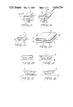
- FIG. 1A is a perspective view of one embodiment of a thermal link made in accordance with the invention.
- FIG. 1B is a perspective view of another embodiment of a thermal link made in accordance with the invention.
- FIG. 2A shows a perspective view of still another embodiment of the invention
- FIG. 2B shows a perspective view of yet another embodiment of the invention
- FIGS. 3A-3D show a cross sectional view of the thermal link along line A-B in FIG. 2B in its free state and when subjected to evenly and unevenly applied pressures;
- FIG. 4 shows a perspective view of a filled elastomeric thermal link made in accordance with this invention.
- FIGS. 5A-5C show alternate embodiments of the structure shown in FIG. 4;
- FIGS. 6a, 6b and 6c, 6d show cross-sectional views of the thermal link of FIG. 4 when in compressed and uncompressed states between irregular surfaces and non-parallel surfaces, respectively;
- FIG. 7 is a cross-sectional view showing details of construction of one embodiment of the thermal link of FIG. 4.
- a thermal link 10 in accordance with the present invention is connected to either the heat source or the heat sink, generally referred to as 12.
- the thermal link may be mounted into a slot formed or cut into the heat source or heat sink as shown, or a U-channel device either molded into the heat source or heat sink or attached thereto as a separate element (not shown) may be utilized.
- the first segment 14 of the thermal link is attached to the channel formed in the heat source or heat sink by any suitable technique which will allow thermal conduction between the heat source or heat sink and the thermal link, such as by soldering.
- the thermal link contains a second segment 18 which is attached to the end of the first segment 14 remote from the heat source or heat sink by means of a joining member 16.
- a third segment 22 of the thermal link is attached to the second segment 18 at the end thereof remote from the first joining member by means of a second joining member 20.
- the surface of the heat source or heat sink which abuts against the third segment 22 of the thermal link 10 may have surface irregularities or have a nonuniform spacing from the heat source or heat sink to which the first segment is mounted over the length or width of the thermal link.
- the existence of the joining members 16 and 20 on either side of the second segment 18 enables segment 18 to operate as a free arm.
- pressure exerted on the third segment 22 by the heat source or heat sink causes the free arm 18 to deform in the planes both transverse and perpendicular to the plane of the paper shown in FIG. 1A, if necessary, so that the third segment and the surface of the heat source or heat sink are in intimate contact.
- This intimate contact eliminates or reduces air spaces between the third segment and the surface of the heat source or heat sink and permits efficient heat transfer through the thermal link from the heat source to the heat sink.
- the large surface contact between the heat source or heat sink and thermal link provides for a low thermal resistance.
- the utilization of the free arm 18 avoids the problem of permanent deformation of the joining member that would occur if the free arm 18 were fixedly mounted.
- the free arm 18 permits the compensation for nonuniformities in the spacing between the heat source and heat sink and/or irregularities of the heat source or heat sink in both the directions transverse to and perpendicular to the plane of the drawing. If the arm 18 were fixedly mounted, then compensation only in the direction transverse to the plane of the drawing could be accomplished.
- the principle of the present invention is further described hereinafter in connection with the embodiment shown in FIG. 2B as illustrated by FIGS. 3A-3D.
- FIG. 1A shows a number of thermal links 10 in a row in the direction perpendicular to the plane of the drawing.
- each of the thermal links 10 can deform independent of the other, thus providing for improved contact with an irregular surface of a heat source or heat sink.
- FIG. 1B shows another modification of the heat source shown in FIG. 1A in which two heat sources or heat sinks can be accommodated by a single thermal link. In the embodiment shown in FIG. 1B, the thermal link which is shown in FIG.
- This configuration can be produced by bending a single strip of material into the desired shape and mounting it into a single channel in the heat source or heat sink to provide a thermal link between two heat sources and a common heat sink, for example.
- FIG. 2A illustrates an alternate embodiment of the invention shown in FIG. 1A.
- the primed reference numerals in FIG. 2A correspond to the unprimed reference numerals in FIG. 1A.
- a fourth segment 32 is connected to the end of the first segment 14 remote from the joining member 16 to form an "S" shaped device.
- the third segment 22' and the fourth segment 32 are of similar but not necessarily identical shape.
- the element 30 may comprise the joining member 16, the first segment 14 and another joining member between the first segment and the fourth segment 32.
- the element 30 can comprise a joining member coupled between the elements 18' and 32 similar to the coupling of joining member 20' between the elements 18' and 22'.
- This embodiment has the advantage of providing a large surface contact area on both the heat source and the heat sink thus obviating the need for the channel shown in the embodiment of FIGS. 1A and 1B.
- this embodiment can be utilized without being attached to either the heat source or the heat sink because the pressure utilized to deform the thermal link can be utilized to maintain the thermal link in position between the heat source and the heat sink.
- FIG. 2B shows a modified form of this embodiment in which a thermal link shown in FIG. 2A is connected to the mirror image of that thermal link by sharing a common third segment 22'.
- the open loops formed by segments 18' and 22' and joining members 20' face each other while the open loops formed by elements 18', 30 and 32 face away from each other.
- This shape provides the advantage of providing improved compensation for irregularities or nonuniform spacing over a full 360° range.
- FIGS. 3A-3D The operation of this form of the invention is further explained below in connection with FIGS. 3A-3D.
- FIG. 3A shows a cross section of the embodiment of FIG. 2B taken along line A-B in its free state, that is, without any pressure applied to deform the link.
- FIG. 3B shows the same thermal link with an even pressure applied between a heat source 34 and a heat sink 36. It should be understood that the positions of the heat source 34 and heat sink 36 could be interchanged in the figure. As illustrated, the heat source 34 and the heat sink 36 are uniformly spaced, that is, substantially parallel.
- FIGS. 3C and 3D show a mounting arrangement in which the heat source 34 and heat sink 36 are not parallel so that the space between them is not uniform.
- the thermal link will align itself so that the segments in contact with both the heat source and heat sink are always in intimate contact.
- the surfaces 22 of FIG. 1B or 32 of FIG. 2B can conform independently to different spacing between the heat source and the heat sink.
- the embodiment shown in FIGS. 2A and 2B can also be utilized in a multisegmented form as discussed for the embodiments of FIGS. 1A and 1B.
- the thermal links shown in FIGS. 1A, 1B, 2A and 2B can be formed from a single piece of material.
- Metals have the advantage of providing high conductivity at low cost and are available in strip form which can easily be bent into the desired shape.
- many metals or metal alloys such as spring tempered beryllium copper, silver alloys or phosphor bronze could be utilized for a thermal link in accordance with the present invention, it is been found that a tempered copper alloy such as CDA alloy 155 strip manufactured by Hussey/Copper Range Co. is particularly advantageous because it provides a high thermal conductivity at low cost while being easily made galvanically compatible with aluminum, a common material for heat sinks.
- FIG. 4 illustrates an alternate form of the present invention in which an elastomeric material is filled with thermally conducting particles to form a mat or sheet 40 with a plurality of raised sections 42 having an air space between each of the sections.
- FIG. 6b shows mat 40 in an uncompressed state and disposed between a heat source 34 having an irregular surface and a heat sink 36.
- FIG. 6d shows mat 40 in an uncompressed state and disposed between a heat source 34 and a heat sink 36 which are not parallel to each other.
- FIGS. 6a and 6c when placed between a heat source and a heat sink, and pressure is applied to deform the raised sections, the raised sections expand laterally into the air spaces between each of the raised sections. This lateral expansion allows numerous advantages over prior art single sheet thermal links.
- the plurality of raised sections each deforming independent of the other permits the thermal link to accommodate irregularities in the surfaces of the heat sink or the heat source (see FIG. 6a) as well as accommodating nonuniformity in the spacing between the heat sink and the heat source (see FIG. 6c).
- each of these raised sections can be made to deform under relatively light pressure so that the excess pressures utilized in prior art approaches can be avoided.
- This lateral spreading of the raised sections also increases the contact area at the interface between the heat source or heat sink, thus increasing the efficiency of the heat transfer.
- the raised sections expanded they thin out reducing the length of the thermal path further reducing the thermal resistance.
- the raised surfaces 42 shown in FIG. 4 are of a generally hemispheric shape. However, many other shapes having the required characteristics can be utilized, as illustrated by the rectangular shapes of FIG. 5A, the modified cylindrical or elongated strip shape of FIG. 5B or the tubular shape of FIG. 5C. The shapes shown in FIGS. 4 and 5A-5C are meant to be illustrative only and not limiting the scope of the present invention.
- each of the raised sections should be such that under maximum compression, each of the raised sections just about touches the other to provide a maximum surface area of contact between the heat source and heat sink.
- a number of filled elastomeric compounds suitable for use in making the thermal link according to this aspect of the present invention are known, for example, CONSIL-C silver-copper filled silicone elastomer or CONSIL-R pure silver filled silicon elastomer, both trademarks of Tecknit. It should be noted that the portions of the mat 40 that connect the raised portions 42, 44, 46 or 48 may or may not be made of the same elastomeric material. As is shown in FIG.
- the surfaces of the heat sources and heat sinks and the surfaces of the segments 22, 22' and 32, herein shown as being flat, could be curved.
- the heat sources or heat sinks could be, for example, the wall of a cylindrical tube and the surfaces of the segments 22, 22' and 32 curved to fit.
Abstract
Description
Claims (8)
Priority Applications (2)
| Application Number | Priority Date | Filing Date | Title |
|---|---|---|---|
| US06/438,560 US4654754A (en) | 1982-11-02 | 1982-11-02 | Thermal link |
| US06/824,834 US4689720A (en) | 1982-11-02 | 1986-01-31 | Thermal link |
Applications Claiming Priority (1)
| Application Number | Priority Date | Filing Date | Title |
|---|---|---|---|
| US06/438,560 US4654754A (en) | 1982-11-02 | 1982-11-02 | Thermal link |
Related Child Applications (1)
| Application Number | Title | Priority Date | Filing Date |
|---|---|---|---|
| US06/824,834 Division US4689720A (en) | 1982-11-02 | 1986-01-31 | Thermal link |
Publications (1)
| Publication Number | Publication Date |
|---|---|
| US4654754A true US4654754A (en) | 1987-03-31 |
Family
ID=23741101
Family Applications (1)
| Application Number | Title | Priority Date | Filing Date |
|---|---|---|---|
| US06/438,560 Expired - Fee Related US4654754A (en) | 1982-11-02 | 1982-11-02 | Thermal link |
Country Status (1)
| Country | Link |
|---|---|
| US (1) | US4654754A (en) |
Cited By (100)
| Publication number | Priority date | Publication date | Assignee | Title |
|---|---|---|---|---|
| EP0282307A1 (en) * | 1987-03-12 | 1988-09-14 | Minnesota Mining And Manufacturing Company | Resilient electrically and thermally conductive flexible composite |
| EP0297793A2 (en) * | 1987-07-02 | 1989-01-04 | AT&T Corp. | Thermal conductor assembly |
| EP0326321A2 (en) * | 1988-01-26 | 1989-08-02 | THE GENERAL ELECTRIC COMPANY, p.l.c. | Housing for electronic device |
| FR2632119A1 (en) * | 1988-05-26 | 1989-12-01 | Bergquist Co | |
| EP0363687A2 (en) * | 1988-09-20 | 1990-04-18 | Nec Corporation | Cooling structure for electronic components |
| US4974119A (en) * | 1988-09-14 | 1990-11-27 | The Charles Stark Draper Laboratories, Inc. | Conforming heat sink assembly |
| US4979074A (en) * | 1989-06-12 | 1990-12-18 | Flavors Technology | Printed circuit board heat sink |
| US4993482A (en) * | 1990-01-09 | 1991-02-19 | Microelectronics And Computer Technology Corporation | Coiled spring heat transfer element |
| US5032944A (en) * | 1989-01-12 | 1991-07-16 | Mitsubishi Denki Kabushiki Kaisha | Membrane type magnetic head |
| US5060114A (en) * | 1990-06-06 | 1991-10-22 | Zenith Electronics Corporation | Conformable pad with thermally conductive additive for heat dissipation |
| WO1993003319A1 (en) * | 1991-07-31 | 1993-02-18 | Tra-Con, Inc. | Controlled highly densified diamond packing of thermally conductive electrically resistive conduit |
| US5213868A (en) * | 1991-08-13 | 1993-05-25 | Chomerics, Inc. | Thermally conductive interface materials and methods of using the same |
| US5305185A (en) * | 1992-09-30 | 1994-04-19 | Samarov Victor M | Coplanar heatsink and electronics assembly |
| US5309320A (en) * | 1991-02-06 | 1994-05-03 | Hughes Aircraft Company | Circuit card assembly conduction converter |
| US5377078A (en) * | 1993-01-26 | 1994-12-27 | Relm Communications Inc. | Apparatus mounting a power semiconductor to a heat sink |
| DE4339786A1 (en) * | 1993-11-18 | 1995-05-24 | Emi Tec Elektronische Material | Arrangement for heat dissipation and method for its production |
| US5438477A (en) * | 1993-08-12 | 1995-08-01 | Lsi Logic Corporation | Die-attach technique for flip-chip style mounting of semiconductor dies |
| WO1996006321A1 (en) * | 1994-08-22 | 1996-02-29 | Iowa State University Research Foundation, Inc. | Heat sink |
| US5510174A (en) * | 1993-07-14 | 1996-04-23 | Chomerics, Inc. | Thermally conductive materials containing titanium diboride filler |
| US5557501A (en) * | 1994-11-18 | 1996-09-17 | Tessera, Inc. | Compliant thermal connectors and assemblies incorporating the same |
| US5649593A (en) * | 1996-01-17 | 1997-07-22 | Kitagawa Industries Co., Ltd. | Radiator member |
| US5653280A (en) * | 1995-11-06 | 1997-08-05 | Ncr Corporation | Heat sink assembly and method of affixing the same to electronic devices |
| US5783862A (en) * | 1992-03-20 | 1998-07-21 | Hewlett-Packard Co. | Electrically conductive thermal interface |
| US5812374A (en) * | 1996-10-28 | 1998-09-22 | Shuff; Gregg Douglas | Electrical circuit cooling device |
| WO1999005722A1 (en) | 1997-07-28 | 1999-02-04 | Parker-Hannifin Corporation | Double-side, thermally conductive adhesive tape for plastic-packaged electronic components |
| US5926944A (en) * | 1996-05-23 | 1999-07-27 | Compaoq Computer Corporation | Method of constructing a shielded electrical component |
| US5931222A (en) * | 1995-11-30 | 1999-08-03 | International Business Machines Coporation | Adhesion promoting layer for bonding polymeric adhesive to metal and a heat sink assembly using same |
| EP0930231A3 (en) * | 1998-01-19 | 1999-09-29 | TRW Inc. | Improved heat conductive interface material |
| EP0986292A2 (en) * | 1998-09-09 | 2000-03-15 | Patent-Treuhand-Gesellschaft für elektrische Glühlampen mbH | Thermal transfer mat for electrical or electronic apparatuses |
| US6096414A (en) * | 1997-11-25 | 2000-08-01 | Parker-Hannifin Corporation | High dielectric strength thermal interface material |
| US6151216A (en) * | 1997-12-04 | 2000-11-21 | Lockheed Martin Corporation | Thermally conductive vibration isolators |
| DE19924289A1 (en) * | 1999-05-27 | 2000-12-07 | Siemens Ag | Electronic circuit module with flexible intermediate layer between electronic components and heat-sink |
| US6162663A (en) * | 1999-04-20 | 2000-12-19 | Schoenstein; Paul G. | Dissipation of heat from a circuit board having bare silicon chips mounted thereon |
| US6219236B1 (en) | 1997-10-20 | 2001-04-17 | Fujitsu, Ltd. | Cooling system for multichip module |
| US6245186B1 (en) * | 1996-12-16 | 2001-06-12 | International Business Machines Corporation | Electronic package with compressible heatsink structure |
| US6275381B1 (en) * | 1998-12-10 | 2001-08-14 | International Business Machines Corporation | Thermal paste preforms as a heat transfer media between a chip and a heat sink and method thereof |
| US6343647B2 (en) * | 2000-01-11 | 2002-02-05 | Thermax International, Ll.C. | Thermal joint and method of use |
| WO2002013264A1 (en) * | 2000-08-04 | 2002-02-14 | Infineon Technologies Ag | Cooling device for electronic components and method for producing said cooling device |
| US20020070688A1 (en) * | 1997-08-26 | 2002-06-13 | Dowling Kevin J. | Light-emitting diode based products |
| US6434006B1 (en) * | 2000-05-12 | 2002-08-13 | Denso Corporation | Semiconductor device having heat radiating member |
| DE10109083A1 (en) * | 2001-02-24 | 2002-10-02 | Conti Temic Microelectronic | Electronic assembly |
| US6496373B1 (en) | 1999-11-04 | 2002-12-17 | Amerasia International Technology, Inc. | Compressible thermally-conductive interface |
| US6497583B1 (en) * | 2001-10-03 | 2002-12-24 | Paricon Technologies Corporation | Interconnection components with integral conductive elastomeric sheet material, and method of manufacturing same |
| US6523608B1 (en) * | 2000-07-31 | 2003-02-25 | Intel Corporation | Thermal interface material on a mesh carrier |
| US6531771B1 (en) | 1999-04-20 | 2003-03-11 | Tyco Electronics Corporation | Dissipation of heat from a circuit board having bare silicon chips mounted thereon |
| DE10142987A1 (en) * | 2001-09-01 | 2003-04-03 | Conti Temic Microelectronic | Heat dissipation element for electronic components |
| US6552907B1 (en) * | 2001-10-11 | 2003-04-22 | Lsi Logic Corporation | BGA heat ball plate spreader, BGA to PCB plate interface |
| US20030076281A1 (en) * | 1997-08-26 | 2003-04-24 | Frederick Marshall Morgan | Diffuse illumination systems and methods |
| US20030152764A1 (en) * | 2002-02-06 | 2003-08-14 | Bunyan Michael H. | Thermal management materials having a phase change dispersion |
| US20030203188A1 (en) * | 2002-02-06 | 2003-10-30 | H. Bunyan Michael | Thermal management materials |
| US6644395B1 (en) | 1999-11-17 | 2003-11-11 | Parker-Hannifin Corporation | Thermal interface material having a zone-coated release linear |
| US6651736B2 (en) * | 2001-06-28 | 2003-11-25 | Intel Corporation | Short carbon fiber enhanced thermal grease |
| US20030222249A1 (en) * | 2002-05-31 | 2003-12-04 | Bunyan Michael H. | Thermally or electrically-conductive form-in-place gap filter |
| US20030230403A1 (en) * | 2002-06-14 | 2003-12-18 | Webb Brent J. | Conductive thermal interface and compound |
| US20040090191A1 (en) * | 1997-08-26 | 2004-05-13 | Color Kinetics, Incorporated | Multicolored led lighting method and apparatus |
| US20040257007A1 (en) * | 1997-12-17 | 2004-12-23 | Color Kinetics, Incorporated | Geometric panel lighting apparatus and methods |
| US6835453B2 (en) | 2001-01-22 | 2004-12-28 | Parker-Hannifin Corporation | Clean release, phase change thermal interface |
| US20040264138A1 (en) * | 2003-06-24 | 2004-12-30 | Intel Corporation | Thermal Interface Apparatus, Systems, and Fabrication methods |
| US20050067157A1 (en) * | 2003-09-08 | 2005-03-31 | Victor Faybishenko | Heat-transfer interface device between a source of heat and a heat-receiving object |
| US20050116667A1 (en) * | 2001-09-17 | 2005-06-02 | Color Kinetics, Incorporated | Tile lighting methods and systems |
| EP1545180A2 (en) * | 2003-12-16 | 2005-06-22 | Patent-Treuhand-Gesellschaft für elektrische Glühlampen mbH | Thermal transfer mat for electrical or electronic apparatuses and process for producing it |
| US6956739B2 (en) | 2002-10-29 | 2005-10-18 | Parker-Hannifin Corporation | High temperature stable thermal interface material |
| US20050236998A1 (en) * | 1997-08-26 | 2005-10-27 | Color Kinetics, Inc. | Light emitting diode based products |
| US20050241801A1 (en) * | 2004-05-03 | 2005-11-03 | Mitchell Jonathan E | Lightweight heat sink |
| US20050270744A1 (en) * | 2004-06-03 | 2005-12-08 | International Business Machines Corporation | Compliant thermal interface for electronic equipment |
| US20060037741A1 (en) * | 2004-08-19 | 2006-02-23 | Fujitsu Limited | Heat transfer sheet, heat transfer structural body and manufacturing method of the heat transfer structural body |
| US20060185836A1 (en) * | 2005-02-24 | 2006-08-24 | Scott Garner | Thermally coupled surfaces having controlled minimum clearance |
| US20060198128A1 (en) * | 2005-02-28 | 2006-09-07 | Color Kinetics Incorporated | Configurations and methods for embedding electronics or light emitters in manufactured materials |
| US20070047209A1 (en) * | 2005-09-01 | 2007-03-01 | Alex Thompson | Heat transfer plate |
| US7186003B2 (en) | 1997-08-26 | 2007-03-06 | Color Kinetics Incorporated | Light-emitting diode based products |
| US20070091574A1 (en) * | 2005-10-26 | 2007-04-26 | Indium Corporation Of America | Technique for forming a thermally conductive interface with patterned metal foil |
| US20070230131A1 (en) * | 2003-01-16 | 2007-10-04 | Bunyan Michael H | Dispensable cured resin |
| US20080068803A1 (en) * | 2006-09-18 | 2008-03-20 | Shyh-Ming Chen | Heat dissipating device holder structure with a thin film thermal conducting medium coating |
| US20080066899A1 (en) * | 2006-09-15 | 2008-03-20 | Zhao-Ren Wang | Tape-like heat sink |
| US20080190585A1 (en) * | 2007-02-08 | 2008-08-14 | Lundell Timothy J | Sealed thermal interface component |
| US20080308229A1 (en) * | 2007-06-13 | 2008-12-18 | Lam Research Corporation | Electrode assembly and plasma processing chamber utilizing thermally conductive gasket and o-rings |
| US20090095424A1 (en) * | 2007-10-12 | 2009-04-16 | Lam Research Corporation | Showerhead electrode assemblies and plasma processing chambers incorporating the same |
| US20090109628A1 (en) * | 2007-10-30 | 2009-04-30 | International Business Machines Corporation | Chip Cooling System with Convex Portion |
| US20090122491A1 (en) * | 2007-11-08 | 2009-05-14 | Martin Yves C | Universal patterned metal thermal interface |
| US20090236040A1 (en) * | 2008-03-18 | 2009-09-24 | Lam Research Corporation | Electrode assembly and plasma processing chamber utilizing thermally conductive gasket |
| US20090244852A1 (en) * | 2008-03-25 | 2009-10-01 | Fujitsu Limited | Heat radiator |
| US20090305509A1 (en) * | 2008-06-09 | 2009-12-10 | Lam Research Corporation | Showerhead electrode assemblies for plasma processing apparatuses |
| US20100038033A1 (en) * | 2007-10-12 | 2010-02-18 | Lam Research Corporation | Anchoring inserts, electrode assemblies, and plasma processing chambers |
| USRE41576E1 (en) | 1996-04-29 | 2010-08-24 | Parker-Hannifin Corporation | Conformal thermal interface material for electronic components |
| US20110024427A1 (en) * | 2009-07-03 | 2011-02-03 | Thales | Device for detecting the opening of a hatch in an item of equipment comprising one or more electronic circuit boards |
| US20110038123A1 (en) * | 2009-08-17 | 2011-02-17 | Seagate Technology Llc | Solid state data storage assembly |
| WO2011019719A1 (en) | 2009-08-12 | 2011-02-17 | Parker-Hannifin Corporation | Fully-cured thermally or electrically-conductive form-in-place gap filler |
| US20110075377A1 (en) * | 2009-09-25 | 2011-03-31 | Raytheon Copany | Heat Sink Interface Having Three-Dimensional Tolerance Compensation |
| US7954236B2 (en) | 2007-02-08 | 2011-06-07 | Lundell Manufacturing Corporation | Method of assembling a sealed thermal interface |
| US20120080171A1 (en) * | 2010-09-30 | 2012-04-05 | Fujitsu Limited | Heat relay mechanism and heat-dissipating fin unit |
| US8289712B2 (en) | 2010-06-21 | 2012-10-16 | International Business Machines Corporation | Flux-free detachable thermal interface between an integrated circuit device and a heat sink |
| RU2470498C1 (en) * | 2011-06-17 | 2012-12-20 | Владимир Иванович Бодрягин | Processor cooler |
| CN102903685A (en) * | 2010-11-04 | 2013-01-30 | 聚信科技有限公司 | Heat conducting pad |
| US8449679B2 (en) | 2008-08-15 | 2013-05-28 | Lam Research Corporation | Temperature controlled hot edge ring assembly |
| CN104392971A (en) * | 2014-11-21 | 2015-03-04 | 中国电子科技集团公司第十四研究所 | Watchband contact finger type heat conduction device |
| CN105611804A (en) * | 2015-12-30 | 2016-05-25 | 杭州华为数字技术有限公司 | Heat conducting pad, heat radiator and electronic product |
| CN105702643A (en) * | 2008-06-20 | 2016-06-22 | 阿尔卡特朗讯美国公司 | Heat-transfer structure |
| US9425124B2 (en) | 2012-02-02 | 2016-08-23 | International Business Machines Corporation | Compliant pin fin heat sink and methods |
| US10815771B2 (en) | 2017-06-26 | 2020-10-27 | HRL Laboratories, LL | Thermal regulation and vibration isolation system |
| WO2022187569A1 (en) | 2021-03-04 | 2022-09-09 | Momentive Performance Materials Inc. | Thermal gel composition |
Citations (13)
| Publication number | Priority date | Publication date | Assignee | Title |
|---|---|---|---|---|
| US2328488A (en) * | 1942-02-09 | 1943-08-31 | B L Electric Mfg Company | Rectifier |
| US3005036A (en) * | 1957-11-21 | 1961-10-17 | Atlas E E Corp | Tube shield |
| US3195084A (en) * | 1962-05-23 | 1965-07-13 | Westinghouse Electric Corp | Electrical apparatus having foil wound windings and metallic duct formers |
| US3264534A (en) * | 1964-04-21 | 1966-08-02 | Vitramon Inc | Electrical component and thermal construction |
| US3694182A (en) * | 1971-04-20 | 1972-09-26 | Ford Motor Co | Glass tempering die construction |
| US3883834A (en) * | 1973-12-13 | 1975-05-13 | Gen Electric | Ballast transformer with heat dissipating device |
| US3920940A (en) * | 1974-07-24 | 1975-11-18 | Colorado Time Systems Inc | Pressure actuated switch and method for making same |
| US3950057A (en) * | 1975-06-02 | 1976-04-13 | Calabro Anthony Denis | Composite printed circuit card guide and holding device |
| US4008487A (en) * | 1974-07-24 | 1977-02-15 | Siemens Aktiengesellschaft | Semiconductor component with pressure contact |
| US4029999A (en) * | 1975-04-10 | 1977-06-14 | Ibm Corporation | Thermally conducting elastomeric device |
| US4151547A (en) * | 1977-09-07 | 1979-04-24 | General Electric Company | Arrangement for heat transfer between a heat source and a heat sink |
| US4172216A (en) * | 1978-05-19 | 1979-10-23 | Sprague Electric Company | Pressure sensitive switch |
| US4394530A (en) * | 1977-09-19 | 1983-07-19 | Kaufman Lance R | Power switching device having improved heat dissipation means |
-
1982
- 1982-11-02 US US06/438,560 patent/US4654754A/en not_active Expired - Fee Related
Patent Citations (13)
| Publication number | Priority date | Publication date | Assignee | Title |
|---|---|---|---|---|
| US2328488A (en) * | 1942-02-09 | 1943-08-31 | B L Electric Mfg Company | Rectifier |
| US3005036A (en) * | 1957-11-21 | 1961-10-17 | Atlas E E Corp | Tube shield |
| US3195084A (en) * | 1962-05-23 | 1965-07-13 | Westinghouse Electric Corp | Electrical apparatus having foil wound windings and metallic duct formers |
| US3264534A (en) * | 1964-04-21 | 1966-08-02 | Vitramon Inc | Electrical component and thermal construction |
| US3694182A (en) * | 1971-04-20 | 1972-09-26 | Ford Motor Co | Glass tempering die construction |
| US3883834A (en) * | 1973-12-13 | 1975-05-13 | Gen Electric | Ballast transformer with heat dissipating device |
| US3920940A (en) * | 1974-07-24 | 1975-11-18 | Colorado Time Systems Inc | Pressure actuated switch and method for making same |
| US4008487A (en) * | 1974-07-24 | 1977-02-15 | Siemens Aktiengesellschaft | Semiconductor component with pressure contact |
| US4029999A (en) * | 1975-04-10 | 1977-06-14 | Ibm Corporation | Thermally conducting elastomeric device |
| US3950057A (en) * | 1975-06-02 | 1976-04-13 | Calabro Anthony Denis | Composite printed circuit card guide and holding device |
| US4151547A (en) * | 1977-09-07 | 1979-04-24 | General Electric Company | Arrangement for heat transfer between a heat source and a heat sink |
| US4394530A (en) * | 1977-09-19 | 1983-07-19 | Kaufman Lance R | Power switching device having improved heat dissipation means |
| US4172216A (en) * | 1978-05-19 | 1979-10-23 | Sprague Electric Company | Pressure sensitive switch |
Non-Patent Citations (11)
| Title |
|---|
| Chomerics Laminates Cho Therm 1674 Brochure, 1981. * |
| Chomerics Laminates Cho-Therm 1674 Brochure, 1981. |
| Chomerics Standard EMI/RFI Conductive Elastomer Gaskets Catalog, 1980, pp. 4 7, 10, 11, 27. * |
| Chomerics Standard EMI/RFI Conductive Elastomer Gaskets Catalog, 1980, pp. 4-7, 10, 11, 27. |
| IBM Technical Disclosure Bulletin, vol. 15, No. 6, Nov. 1972, p. 1950. * |
| Instrument Specialties Co. Inc., Precision Springs Catalog 15 B, 1981, pp. 8, 10, 11 15 plus insert ISC 307. * |
| Instrument Specialties Co. Inc., Precision Springs Catalog 15-B, 1981, pp. 8, 10, 11-15 plus insert ISC-307. |
| Tecknit EMI Shielding Products Catalog, 1980, pp. B 1, B 4, C 2, D 1 thru D 3, D 860, G 5. * |
| Tecknit EMI Shielding Products Catalog, 1980, pp. B-1, B-4, C-2, D-1 thru D-3, D-860, G-5. |
| U.S. Department of Defense, Thermal Application Handbook for Standard Electronic Modules Program TP529, Mar. 1981, pp. 6 26 thru 6 40. * |
| U.S. Department of Defense, Thermal Application Handbook for Standard Electronic Modules Program TP529, Mar. 1981, pp. 6-26 thru 6-40. |
Cited By (162)
| Publication number | Priority date | Publication date | Assignee | Title |
|---|---|---|---|---|
| EP0282307A1 (en) * | 1987-03-12 | 1988-09-14 | Minnesota Mining And Manufacturing Company | Resilient electrically and thermally conductive flexible composite |
| EP0297793A3 (en) * | 1987-07-02 | 1989-11-02 | American Telephone And Telegraph Company | Thermal conductor assembly |
| EP0297793A2 (en) * | 1987-07-02 | 1989-01-04 | AT&T Corp. | Thermal conductor assembly |
| US4838347A (en) * | 1987-07-02 | 1989-06-13 | American Telephone And Telegraph Company At&T Bell Laboratories | Thermal conductor assembly |
| GB2214719B (en) * | 1988-01-26 | 1991-07-24 | Gen Electric Co Plc | Housing for electronic device |
| US4999741A (en) * | 1988-01-26 | 1991-03-12 | The General Electric Company, P.L.C. | Package in the heat dissipation of Electronic devices |
| GB2214719A (en) * | 1988-01-26 | 1989-09-06 | Gen Electric Co Plc | Housing for electronic devices |
| EP0326321A3 (en) * | 1988-01-26 | 1990-05-30 | THE GENERAL ELECTRIC COMPANY, p.l.c. | Housing for electronic device |
| EP0326321A2 (en) * | 1988-01-26 | 1989-08-02 | THE GENERAL ELECTRIC COMPANY, p.l.c. | Housing for electronic device |
| FR2632119A1 (en) * | 1988-05-26 | 1989-12-01 | Bergquist Co | |
| US4974119A (en) * | 1988-09-14 | 1990-11-27 | The Charles Stark Draper Laboratories, Inc. | Conforming heat sink assembly |
| US5014777A (en) * | 1988-09-20 | 1991-05-14 | Nec Corporation | Cooling structure |
| EP0363687A3 (en) * | 1988-09-20 | 1991-04-10 | Nec Corporation | Cooling structure for electronic components |
| EP0363687A2 (en) * | 1988-09-20 | 1990-04-18 | Nec Corporation | Cooling structure for electronic components |
| US5032944A (en) * | 1989-01-12 | 1991-07-16 | Mitsubishi Denki Kabushiki Kaisha | Membrane type magnetic head |
| US4979074A (en) * | 1989-06-12 | 1990-12-18 | Flavors Technology | Printed circuit board heat sink |
| US4993482A (en) * | 1990-01-09 | 1991-02-19 | Microelectronics And Computer Technology Corporation | Coiled spring heat transfer element |
| US5060114A (en) * | 1990-06-06 | 1991-10-22 | Zenith Electronics Corporation | Conformable pad with thermally conductive additive for heat dissipation |
| US5309320A (en) * | 1991-02-06 | 1994-05-03 | Hughes Aircraft Company | Circuit card assembly conduction converter |
| WO1993003319A1 (en) * | 1991-07-31 | 1993-02-18 | Tra-Con, Inc. | Controlled highly densified diamond packing of thermally conductive electrically resistive conduit |
| US5213868A (en) * | 1991-08-13 | 1993-05-25 | Chomerics, Inc. | Thermally conductive interface materials and methods of using the same |
| US5783862A (en) * | 1992-03-20 | 1998-07-21 | Hewlett-Packard Co. | Electrically conductive thermal interface |
| US5305185A (en) * | 1992-09-30 | 1994-04-19 | Samarov Victor M | Coplanar heatsink and electronics assembly |
| US5377078A (en) * | 1993-01-26 | 1994-12-27 | Relm Communications Inc. | Apparatus mounting a power semiconductor to a heat sink |
| US5510174A (en) * | 1993-07-14 | 1996-04-23 | Chomerics, Inc. | Thermally conductive materials containing titanium diboride filler |
| US5438477A (en) * | 1993-08-12 | 1995-08-01 | Lsi Logic Corporation | Die-attach technique for flip-chip style mounting of semiconductor dies |
| DE4339786A1 (en) * | 1993-11-18 | 1995-05-24 | Emi Tec Elektronische Material | Arrangement for heat dissipation and method for its production |
| EP0654819A2 (en) * | 1993-11-18 | 1995-05-24 | EMI-TEC, ELEKTRONISCHE MATERIALIEN GmbH | Heat dissipation device and associated fabrication process |
| EP0654819A3 (en) * | 1993-11-18 | 1995-10-18 | Emi Tec Elektronische Material | Heat dissipation device and associated fabrication process. |
| US5518758A (en) * | 1993-11-18 | 1996-05-21 | Emi-Tec Elektronische Materialien Gmbh | Arrangement for the conduction away of heat and a process for the production thereof |
| DE4339786C5 (en) * | 1993-11-18 | 2004-02-05 | Emi-Tec Elektronische Materialien Gmbh | Process for producing a heat dissipation arrangement |
| CN1057188C (en) * | 1993-11-18 | 2000-10-04 | 艾米-塔克电子材料有限公司 | Radiating structure and manufacture of same |
| WO1996006321A1 (en) * | 1994-08-22 | 1996-02-29 | Iowa State University Research Foundation, Inc. | Heat sink |
| US5557501A (en) * | 1994-11-18 | 1996-09-17 | Tessera, Inc. | Compliant thermal connectors and assemblies incorporating the same |
| US5653280A (en) * | 1995-11-06 | 1997-08-05 | Ncr Corporation | Heat sink assembly and method of affixing the same to electronic devices |
| US5931222A (en) * | 1995-11-30 | 1999-08-03 | International Business Machines Coporation | Adhesion promoting layer for bonding polymeric adhesive to metal and a heat sink assembly using same |
| US5649593A (en) * | 1996-01-17 | 1997-07-22 | Kitagawa Industries Co., Ltd. | Radiator member |
| USRE41576E1 (en) | 1996-04-29 | 2010-08-24 | Parker-Hannifin Corporation | Conformal thermal interface material for electronic components |
| US5926944A (en) * | 1996-05-23 | 1999-07-27 | Compaoq Computer Corporation | Method of constructing a shielded electrical component |
| US5812374A (en) * | 1996-10-28 | 1998-09-22 | Shuff; Gregg Douglas | Electrical circuit cooling device |
| US6245186B1 (en) * | 1996-12-16 | 2001-06-12 | International Business Machines Corporation | Electronic package with compressible heatsink structure |
| WO1999005722A1 (en) | 1997-07-28 | 1999-02-04 | Parker-Hannifin Corporation | Double-side, thermally conductive adhesive tape for plastic-packaged electronic components |
| US7462997B2 (en) | 1997-08-26 | 2008-12-09 | Philips Solid-State Lighting Solutions, Inc. | Multicolored LED lighting method and apparatus |
| US20030076281A1 (en) * | 1997-08-26 | 2003-04-24 | Frederick Marshall Morgan | Diffuse illumination systems and methods |
| US7186003B2 (en) | 1997-08-26 | 2007-03-06 | Color Kinetics Incorporated | Light-emitting diode based products |
| US20070195526A1 (en) * | 1997-08-26 | 2007-08-23 | Color Kinetics Incorporated | Wireless lighting control methods and apparatus |
| US7161311B2 (en) | 1997-08-26 | 2007-01-09 | Color Kinetics Incorporated | Multicolored LED lighting method and apparatus |
| US7659674B2 (en) | 1997-08-26 | 2010-02-09 | Philips Solid-State Lighting Solutions, Inc. | Wireless lighting control methods and apparatus |
| US20030214259A9 (en) * | 1997-08-26 | 2003-11-20 | Dowling Kevin J. | Light-emitting diode based products |
| US7064498B2 (en) | 1997-08-26 | 2006-06-20 | Color Kinetics Incorporated | Light-emitting diode based products |
| US20040090191A1 (en) * | 1997-08-26 | 2004-05-13 | Color Kinetics, Incorporated | Multicolored led lighting method and apparatus |
| US7352339B2 (en) | 1997-08-26 | 2008-04-01 | Philips Solid-State Lighting Solutions | Diffuse illumination systems and methods |
| US7274160B2 (en) | 1997-08-26 | 2007-09-25 | Color Kinetics Incorporated | Multicolored lighting method and apparatus |
| US20020070688A1 (en) * | 1997-08-26 | 2002-06-13 | Dowling Kevin J. | Light-emitting diode based products |
| US20050236998A1 (en) * | 1997-08-26 | 2005-10-27 | Color Kinetics, Inc. | Light emitting diode based products |
| US6219236B1 (en) | 1997-10-20 | 2001-04-17 | Fujitsu, Ltd. | Cooling system for multichip module |
| US6096414A (en) * | 1997-11-25 | 2000-08-01 | Parker-Hannifin Corporation | High dielectric strength thermal interface material |
| US6151216A (en) * | 1997-12-04 | 2000-11-21 | Lockheed Martin Corporation | Thermally conductive vibration isolators |
| US20040257007A1 (en) * | 1997-12-17 | 2004-12-23 | Color Kinetics, Incorporated | Geometric panel lighting apparatus and methods |
| US7180252B2 (en) | 1997-12-17 | 2007-02-20 | Color Kinetics Incorporated | Geometric panel lighting apparatus and methods |
| EP0930231A3 (en) * | 1998-01-19 | 1999-09-29 | TRW Inc. | Improved heat conductive interface material |
| US6131646A (en) * | 1998-01-19 | 2000-10-17 | Trw Inc. | Heat conductive interface material |
| EP0986292A3 (en) * | 1998-09-09 | 2000-12-20 | Patent-Treuhand-Gesellschaft für elektrische Glühlampen mbH | Thermal transfer mat for electrical or electronic apparatuses |
| EP0986292A2 (en) * | 1998-09-09 | 2000-03-15 | Patent-Treuhand-Gesellschaft für elektrische Glühlampen mbH | Thermal transfer mat for electrical or electronic apparatuses |
| US6275381B1 (en) * | 1998-12-10 | 2001-08-14 | International Business Machines Corporation | Thermal paste preforms as a heat transfer media between a chip and a heat sink and method thereof |
| US6162663A (en) * | 1999-04-20 | 2000-12-19 | Schoenstein; Paul G. | Dissipation of heat from a circuit board having bare silicon chips mounted thereon |
| US6531771B1 (en) | 1999-04-20 | 2003-03-11 | Tyco Electronics Corporation | Dissipation of heat from a circuit board having bare silicon chips mounted thereon |
| US6377460B1 (en) * | 1999-05-27 | 2002-04-23 | Infineon Technologies Ag | Electronic circuit having a flexible intermediate layer between electronic components and a heat sink |
| DE19924289A1 (en) * | 1999-05-27 | 2000-12-07 | Siemens Ag | Electronic circuit module with flexible intermediate layer between electronic components and heat-sink |
| US6496373B1 (en) | 1999-11-04 | 2002-12-17 | Amerasia International Technology, Inc. | Compressible thermally-conductive interface |
| US6644395B1 (en) | 1999-11-17 | 2003-11-11 | Parker-Hannifin Corporation | Thermal interface material having a zone-coated release linear |
| US6343647B2 (en) * | 2000-01-11 | 2002-02-05 | Thermax International, Ll.C. | Thermal joint and method of use |
| US6434006B1 (en) * | 2000-05-12 | 2002-08-13 | Denso Corporation | Semiconductor device having heat radiating member |
| US6523608B1 (en) * | 2000-07-31 | 2003-02-25 | Intel Corporation | Thermal interface material on a mesh carrier |
| WO2002013264A1 (en) * | 2000-08-04 | 2002-02-14 | Infineon Technologies Ag | Cooling device for electronic components and method for producing said cooling device |
| US6835453B2 (en) | 2001-01-22 | 2004-12-28 | Parker-Hannifin Corporation | Clean release, phase change thermal interface |
| DE10109083A1 (en) * | 2001-02-24 | 2002-10-02 | Conti Temic Microelectronic | Electronic assembly |
| DE10109083B4 (en) * | 2001-02-24 | 2006-07-13 | Conti Temic Microelectronic Gmbh | Electronic module |
| US6651736B2 (en) * | 2001-06-28 | 2003-11-25 | Intel Corporation | Short carbon fiber enhanced thermal grease |
| US20040060691A1 (en) * | 2001-06-28 | 2004-04-01 | Intel Corporation | Short carbon fiber enhanced thermal grease |
| DE10142987A1 (en) * | 2001-09-01 | 2003-04-03 | Conti Temic Microelectronic | Heat dissipation element for electronic components |
| US20050116667A1 (en) * | 2001-09-17 | 2005-06-02 | Color Kinetics, Incorporated | Tile lighting methods and systems |
| US7358929B2 (en) | 2001-09-17 | 2008-04-15 | Philips Solid-State Lighting Solutions, Inc. | Tile lighting methods and systems |
| US6497583B1 (en) * | 2001-10-03 | 2002-12-24 | Paricon Technologies Corporation | Interconnection components with integral conductive elastomeric sheet material, and method of manufacturing same |
| US6649115B2 (en) * | 2001-10-03 | 2003-11-18 | Paricon Technologies Corporation | Method of manufacturing interconnection components with integral conductive elastomeric sheet material |
| US6552907B1 (en) * | 2001-10-11 | 2003-04-22 | Lsi Logic Corporation | BGA heat ball plate spreader, BGA to PCB plate interface |
| US7682690B2 (en) | 2002-02-06 | 2010-03-23 | Parker-Hannifin Corporation | Thermal management materials having a phase change dispersion |
| US6946190B2 (en) | 2002-02-06 | 2005-09-20 | Parker-Hannifin Corporation | Thermal management materials |
| US20030152764A1 (en) * | 2002-02-06 | 2003-08-14 | Bunyan Michael H. | Thermal management materials having a phase change dispersion |
| US20030203188A1 (en) * | 2002-02-06 | 2003-10-30 | H. Bunyan Michael | Thermal management materials |
| US7208192B2 (en) | 2002-05-31 | 2007-04-24 | Parker-Hannifin Corporation | Thermally or electrically-conductive form-in-place gap filter |
| US20030222249A1 (en) * | 2002-05-31 | 2003-12-04 | Bunyan Michael H. | Thermally or electrically-conductive form-in-place gap filter |
| US20030230403A1 (en) * | 2002-06-14 | 2003-12-18 | Webb Brent J. | Conductive thermal interface and compound |
| US6956739B2 (en) | 2002-10-29 | 2005-10-18 | Parker-Hannifin Corporation | High temperature stable thermal interface material |
| US8119191B2 (en) | 2003-01-16 | 2012-02-21 | Parker-Hannifin Corporation | Dispensable cured resin |
| US20070230131A1 (en) * | 2003-01-16 | 2007-10-04 | Bunyan Michael H | Dispensable cured resin |
| US20040264138A1 (en) * | 2003-06-24 | 2004-12-30 | Intel Corporation | Thermal Interface Apparatus, Systems, and Fabrication methods |
| US7317258B2 (en) | 2003-06-24 | 2008-01-08 | Intel Corporation | Thermal interface apparatus, systems, and fabrication methods |
| US7042729B2 (en) * | 2003-06-24 | 2006-05-09 | Intel Corporation | Thermal interface apparatus, systems, and fabrication methods |
| US20060146501A1 (en) * | 2003-06-24 | 2006-07-06 | Intel Corporation | Thermal interface apparatus, systems, and fabrication methods |
| US20050067157A1 (en) * | 2003-09-08 | 2005-03-31 | Victor Faybishenko | Heat-transfer interface device between a source of heat and a heat-receiving object |
| US7137444B2 (en) * | 2003-09-08 | 2006-11-21 | Pacific Rubber & Packing, Inc. | Heat-transfer interface device between a source of heat and a heat-receiving object |
| EP1545180A3 (en) * | 2003-12-16 | 2008-03-05 | Patent-Treuhand-Gesellschaft für elektrische Glühlampen mbH | Thermal transfer mat for electrical or electronic apparatuses and process for producing it |
| EP1545180A2 (en) * | 2003-12-16 | 2005-06-22 | Patent-Treuhand-Gesellschaft für elektrische Glühlampen mbH | Thermal transfer mat for electrical or electronic apparatuses and process for producing it |
| US7147041B2 (en) | 2004-05-03 | 2006-12-12 | Parker-Hannifin Corporation | Lightweight heat sink |
| US20050241801A1 (en) * | 2004-05-03 | 2005-11-03 | Mitchell Jonathan E | Lightweight heat sink |
| US7200006B2 (en) * | 2004-06-03 | 2007-04-03 | International Business Machines Corporation | Compliant thermal interface for electronic equipment |
| US20050270744A1 (en) * | 2004-06-03 | 2005-12-08 | International Business Machines Corporation | Compliant thermal interface for electronic equipment |
| US20060037741A1 (en) * | 2004-08-19 | 2006-02-23 | Fujitsu Limited | Heat transfer sheet, heat transfer structural body and manufacturing method of the heat transfer structural body |
| US7610678B2 (en) * | 2004-08-19 | 2009-11-03 | Fujitsu Limited | Heat transfer sheet, heat transfer structural body and manufacturing method of the heat transfer structural body |
| US20060185836A1 (en) * | 2005-02-24 | 2006-08-24 | Scott Garner | Thermally coupled surfaces having controlled minimum clearance |
| US7543956B2 (en) | 2005-02-28 | 2009-06-09 | Philips Solid-State Lighting Solutions, Inc. | Configurations and methods for embedding electronics or light emitters in manufactured materials |
| US20060198128A1 (en) * | 2005-02-28 | 2006-09-07 | Color Kinetics Incorporated | Configurations and methods for embedding electronics or light emitters in manufactured materials |
| US20070047209A1 (en) * | 2005-09-01 | 2007-03-01 | Alex Thompson | Heat transfer plate |
| US7646608B2 (en) * | 2005-09-01 | 2010-01-12 | Gm Global Technology Operations, Inc. | Heat transfer plate |
| US7593228B2 (en) * | 2005-10-26 | 2009-09-22 | Indium Corporation Of America | Technique for forming a thermally conductive interface with patterned metal foil |
| US20070091574A1 (en) * | 2005-10-26 | 2007-04-26 | Indium Corporation Of America | Technique for forming a thermally conductive interface with patterned metal foil |
| US20080066899A1 (en) * | 2006-09-15 | 2008-03-20 | Zhao-Ren Wang | Tape-like heat sink |
| US20080068803A1 (en) * | 2006-09-18 | 2008-03-20 | Shyh-Ming Chen | Heat dissipating device holder structure with a thin film thermal conducting medium coating |
| US8448693B2 (en) | 2007-02-08 | 2013-05-28 | Lundell Manufacturing Corporation | Sealed thermal interface component |
| US7954236B2 (en) | 2007-02-08 | 2011-06-07 | Lundell Manufacturing Corporation | Method of assembling a sealed thermal interface |
| US20080190585A1 (en) * | 2007-02-08 | 2008-08-14 | Lundell Timothy J | Sealed thermal interface component |
| US8216418B2 (en) | 2007-06-13 | 2012-07-10 | Lam Research Corporation | Electrode assembly and plasma processing chamber utilizing thermally conductive gasket and o-rings |
| US20080308229A1 (en) * | 2007-06-13 | 2008-12-18 | Lam Research Corporation | Electrode assembly and plasma processing chamber utilizing thermally conductive gasket and o-rings |
| US20100038033A1 (en) * | 2007-10-12 | 2010-02-18 | Lam Research Corporation | Anchoring inserts, electrode assemblies, and plasma processing chambers |
| US8268117B2 (en) | 2007-10-12 | 2012-09-18 | Lam Research Corporation | Showerhead electrodes |
| US8187414B2 (en) | 2007-10-12 | 2012-05-29 | Lam Research Corporation | Anchoring inserts, electrode assemblies, and plasma processing chambers |
| US8152954B2 (en) | 2007-10-12 | 2012-04-10 | Lam Research Corporation | Showerhead electrode assemblies and plasma processing chambers incorporating the same |
| US20090095424A1 (en) * | 2007-10-12 | 2009-04-16 | Lam Research Corporation | Showerhead electrode assemblies and plasma processing chambers incorporating the same |
| US20090109628A1 (en) * | 2007-10-30 | 2009-04-30 | International Business Machines Corporation | Chip Cooling System with Convex Portion |
| US7907410B2 (en) * | 2007-11-08 | 2011-03-15 | International Business Machines Corporation | Universal patterned metal thermal interface |
| US20090122491A1 (en) * | 2007-11-08 | 2009-05-14 | Martin Yves C | Universal patterned metal thermal interface |
| US8187413B2 (en) | 2008-03-18 | 2012-05-29 | Lam Research Corporation | Electrode assembly and plasma processing chamber utilizing thermally conductive gasket |
| US20090236040A1 (en) * | 2008-03-18 | 2009-09-24 | Lam Research Corporation | Electrode assembly and plasma processing chamber utilizing thermally conductive gasket |
| US20090244852A1 (en) * | 2008-03-25 | 2009-10-01 | Fujitsu Limited | Heat radiator |
| US8004846B2 (en) * | 2008-03-25 | 2011-08-23 | Fujitsu Limited | Heat radiator |
| US8679288B2 (en) | 2008-06-09 | 2014-03-25 | Lam Research Corporation | Showerhead electrode assemblies for plasma processing apparatuses |
| US9899228B2 (en) | 2008-06-09 | 2018-02-20 | Lam Research Corporation | Showerhead electrode assemblies for plasma processing apparatuses |
| US20090305509A1 (en) * | 2008-06-09 | 2009-12-10 | Lam Research Corporation | Showerhead electrode assemblies for plasma processing apparatuses |
| CN105702643A (en) * | 2008-06-20 | 2016-06-22 | 阿尔卡特朗讯美国公司 | Heat-transfer structure |
| US8449679B2 (en) | 2008-08-15 | 2013-05-28 | Lam Research Corporation | Temperature controlled hot edge ring assembly |
| US9023177B2 (en) | 2008-10-15 | 2015-05-05 | Lam Research Corporation | Anchoring inserts, electrode assemblies, and plasma processing chambers |
| US8508380B2 (en) * | 2009-07-03 | 2013-08-13 | Thales | Device for detecting the opening of a hatch in an item of equipment comprising one or more electronic circuit boards |
| US20110024427A1 (en) * | 2009-07-03 | 2011-02-03 | Thales | Device for detecting the opening of a hatch in an item of equipment comprising one or more electronic circuit boards |
| WO2011019719A1 (en) | 2009-08-12 | 2011-02-17 | Parker-Hannifin Corporation | Fully-cured thermally or electrically-conductive form-in-place gap filler |
| US20110038123A1 (en) * | 2009-08-17 | 2011-02-17 | Seagate Technology Llc | Solid state data storage assembly |
| US8199506B2 (en) * | 2009-08-17 | 2012-06-12 | Seagate Technology, Llc | Solid state data storage assembly |
| US20110075377A1 (en) * | 2009-09-25 | 2011-03-31 | Raytheon Copany | Heat Sink Interface Having Three-Dimensional Tolerance Compensation |
| US8537552B2 (en) * | 2009-09-25 | 2013-09-17 | Raytheon Company | Heat sink interface having three-dimensional tolerance compensation |
| US8289712B2 (en) | 2010-06-21 | 2012-10-16 | International Business Machines Corporation | Flux-free detachable thermal interface between an integrated circuit device and a heat sink |
| US20120080171A1 (en) * | 2010-09-30 | 2012-04-05 | Fujitsu Limited | Heat relay mechanism and heat-dissipating fin unit |
| CN102903685A (en) * | 2010-11-04 | 2013-01-30 | 聚信科技有限公司 | Heat conducting pad |
| CN102903685B (en) * | 2010-11-04 | 2015-12-16 | 聚信科技有限公司 | A kind of heat conductive pad of electronic equipment |
| RU2470498C1 (en) * | 2011-06-17 | 2012-12-20 | Владимир Иванович Бодрягин | Processor cooler |
| US9425124B2 (en) | 2012-02-02 | 2016-08-23 | International Business Machines Corporation | Compliant pin fin heat sink and methods |
| US9997435B2 (en) | 2012-02-02 | 2018-06-12 | International Business Machines Corporation | Compliant pin fin heat sink and methods |
| US11158565B2 (en) | 2012-02-02 | 2021-10-26 | International Business Machines Corporation | Compliant pin fin heat sink and methods |
| CN104392971B (en) * | 2014-11-21 | 2017-12-01 | 中国电子科技集团公司第十四研究所 | A kind of watchband-shaped contactor formula heat conducting device |
| CN104392971A (en) * | 2014-11-21 | 2015-03-04 | 中国电子科技集团公司第十四研究所 | Watchband contact finger type heat conduction device |
| CN105611804A (en) * | 2015-12-30 | 2016-05-25 | 杭州华为数字技术有限公司 | Heat conducting pad, heat radiator and electronic product |
| US10815771B2 (en) | 2017-06-26 | 2020-10-27 | HRL Laboratories, LL | Thermal regulation and vibration isolation system |
| WO2022187569A1 (en) | 2021-03-04 | 2022-09-09 | Momentive Performance Materials Inc. | Thermal gel composition |
Similar Documents
| Publication | Publication Date | Title |
|---|---|---|
| US4654754A (en) | Thermal link | |
| US4689720A (en) | Thermal link | |
| EP0625871B1 (en) | Electronic component heat sink attachment using a canted coil spring | |
| US9968001B2 (en) | Heat dissipation assembly and communications device | |
| US7663883B2 (en) | Heat transfer mechanism, heat dissipation system, and communication apparatus | |
| US4314311A (en) | Plug-in card support providing electric and thermal connections | |
| US4993482A (en) | Coiled spring heat transfer element | |
| US4707726A (en) | Heat sink mounting arrangement for a semiconductor | |
| EP0622983B1 (en) | Electronic component heat sink attachment using a low force spring | |
| US5611696A (en) | High density and high current capacity pad-to-pad connector comprising of spring connector elements (SCE) | |
| CN100593366C (en) | Heat sink tab for optical sub-assembly | |
| US6873528B2 (en) | Supplemental heat conduction path for card to chassis heat dissipation | |
| US10667431B1 (en) | Memory module cooling | |
| EP0031448A2 (en) | Thermal conduction module for integrated circuit chips | |
| US20050167806A1 (en) | Method and apparatus for providing an integrated circuit cover | |
| KR20100133491A (en) | Thermally conductive mounting element for attachment of printed circuit board to heat sink | |
| CN216488027U (en) | Chip module and circuit board | |
| US3656183A (en) | Connector assembly | |
| EP3644696B1 (en) | Floating-type heat sink and elastic bracket therefor | |
| US6545872B1 (en) | Heat sink for edge connectors | |
| US20010033476A1 (en) | Thermal/mechanical springbeam mechanism for heat transfer from heat source to heat dissipating device | |
| JPH0447962Y2 (en) | ||
| US6018460A (en) | Flexible thermal conductor with electromagnetic interference shielding capability for electronic components | |
| CN209845602U (en) | Elastic heat conducting structure | |
| US5268813A (en) | Flexible printed circuit package and flexible printed circuit for incorporating in such a package |
Legal Events
| Date | Code | Title | Description |
|---|---|---|---|
| AS | Assignment |
Owner name: FAIRCHILD WESTON SYSTEMS, INC. 300 ROBBINS LANE, S Free format text: ASSIGNMENT OF ASSIGNORS INTEREST.;ASSIGNOR:DASZKOWSKI, JOSEPH M.;REEL/FRAME:004550/0923 Effective date: 19860506 Owner name: FAIRCHILD WESTON SYSTEMS, INC., NEW YORK Free format text: ASSIGNMENT OF ASSIGNORS INTEREST;ASSIGNOR:DASZKOWSKI, JOSEPH M.;REEL/FRAME:004550/0923 Effective date: 19860506 |
|
| REMI | Maintenance fee reminder mailed | ||
| LAPS | Lapse for failure to pay maintenance fees | ||
| STCH | Information on status: patent discontinuation |
Free format text: PATENT EXPIRED DUE TO NONPAYMENT OF MAINTENANCE FEES UNDER 37 CFR 1.362 |
|
| FP | Lapsed due to failure to pay maintenance fee |
Effective date: 19910331 |