US4665582A - Lightweight battery powered suction broom - Google Patents

Lightweight battery powered suction broom Download PDF

Info

Publication number
US4665582A
US4665582A US06/704,567 US70456785A US4665582A US 4665582 A US4665582 A US 4665582A US 70456785 A US70456785 A US 70456785A US 4665582 A US4665582 A US 4665582A
Authority
US
United States
Prior art keywords
assembly
mounting
canister
nozzle
vacuum cleaner
Prior art date
Legal status (The legal status is an assumption and is not a legal conclusion. Google has not performed a legal analysis and makes no representation as to the accuracy of the status listed.)
Expired - Lifetime
Application number
US06/704,567
Inventor
Clark S. Richmond
Joyce K. Thomas
Samuel E. Hohulin
Current Assignee (The listed assignees may be inaccurate. Google has not performed a legal analysis and makes no representation or warranty as to the accuracy of the list.)
White Consolidated Industries Inc
Original Assignee
National Union Electric Corp
Priority date (The priority date is an assumption and is not a legal conclusion. Google has not performed a legal analysis and makes no representation as to the accuracy of the date listed.)
Filing date
Publication date
Family has litigation
First worldwide family litigation filed litigation Critical https://patents.darts-ip.com/?family=24830038&utm_source=google_patent&utm_medium=platform_link&utm_campaign=public_patent_search&patent=US4665582(A) "Global patent litigation dataset” by Darts-ip is licensed under a Creative Commons Attribution 4.0 International License.
Application filed by National Union Electric Corp filed Critical National Union Electric Corp
Priority to US06/704,567 priority Critical patent/US4665582A/en
Assigned to NATIONAL UNION ELECTRIC CORPORATION reassignment NATIONAL UNION ELECTRIC CORPORATION ASSIGNMENT OF ASSIGNORS INTEREST. Assignors: HOHULIN, SAMUEL E., RICHMOND, CLARK S., THOMAS, JOYCE K.
Priority to AU52876/86A priority patent/AU574260B2/en
Priority to NO860368A priority patent/NO168455C/en
Priority to NZ215179A priority patent/NZ215179A/en
Priority to EP86850055A priority patent/EP0192624B1/en
Priority to DE8686850055T priority patent/DE3666333D1/en
Priority to AT86850055T priority patent/ATE47294T1/en
Priority to DK83286A priority patent/DK83286A/en
Priority to FI860777A priority patent/FI84227C/en
Priority to JP61036547A priority patent/JPS61196928A/en
Publication of US4665582A publication Critical patent/US4665582A/en
Application granted granted Critical
Assigned to WHITE CONSOLIDATED INDUSTRIES, INC., A CORP. OF DE reassignment WHITE CONSOLIDATED INDUSTRIES, INC., A CORP. OF DE MERGER (SEE DOCUMENT FOR DETAILS). Assignors: NATIONAL UNION ELECTRIC CORPORATION
Anticipated expiration legal-status Critical
Expired - Lifetime legal-status Critical Current

Links

Images

Classifications

    • AHUMAN NECESSITIES
    • A47FURNITURE; DOMESTIC ARTICLES OR APPLIANCES; COFFEE MILLS; SPICE MILLS; SUCTION CLEANERS IN GENERAL
    • A47LDOMESTIC WASHING OR CLEANING; SUCTION CLEANERS IN GENERAL
    • A47L5/00Structural features of suction cleaners
    • A47L5/12Structural features of suction cleaners with power-driven air-pumps or air-compressors, e.g. driven by motor vehicle engine vacuum
    • A47L5/22Structural features of suction cleaners with power-driven air-pumps or air-compressors, e.g. driven by motor vehicle engine vacuum with rotary fans
    • A47L5/24Hand-supported suction cleaners

Landscapes

  • Filters For Electric Vacuum Cleaners (AREA)
  • Addition Polymer Or Copolymer, Post-Treatments, Or Chemical Modifications (AREA)
  • Electric Suction Cleaners (AREA)
  • Manufacturing Of Electric Cables (AREA)
  • Fittings On The Vehicle Exterior For Carrying Loads, And Devices For Holding Or Mounting Articles (AREA)
  • Polymerisation Methods In General (AREA)
  • Electromechanical Clocks (AREA)
  • Hybrid Cells (AREA)
  • Secondary Cells (AREA)
  • Electric Vacuum Cleaner (AREA)

Abstract

A lightweight broom having a rechargeable battery powered vacuum pump and a mounting assembly for pivotally mounting a nozzle. The mounting assembly and power assembly are spaced apart on a frame carrying both assemblies, and a filter bag arrangement is removably received therebetween. The filter bag arrangement includes a canister adapted to removably fit on a frame between the mounting assembly and the power assembly.

Description

This invention relates to vacuum cleaners, and more in particular a vacuum cleaner apparatus especially adapted for hand held, portable operation.
The invention is directed to the provision of a portable vacuum cleaner that is readily and economically fabricated, and easy and reliable to use, and that may be recharged in a simple manner.
Briefly stated, in accordance with the invention, a portable vacuum cleaner is comprised of a frame encorporating a mounting assembly for pivotally mounting a nozzle assembly, and a power assembly including a vacuum pump. The mounting assembly and the power assembly are spaced apart on the frame, so that a filter bag assembly may be removably received therebetween.
The nozzle assembly is comprised of lower and upper nozzle sections adapted to be assembled on opposite sides of a hollow mounting cylinder of the mounting assembly, in order to permit limited pivotal movement of the nozzle assembly. Forward and rear wheels are provided in the lower nozzle section. A recess extends transversly in the bottom of the lower nozzle section, terminating in a central aperture communicating with the hollow mounting cylinder, in order to direct air from the nozzle assembly to the vacuum pump.
The filter bag assembly is comprised of a canister adapted to be removable fit on the frame between the mounting assembly and the power assembly. The canister is pivoted at the mounting assembly and held by a latch at the power assembly. A longitudinal groove in the bottom of the canister receives a bar-shaped element of the frame, both to inhibit lateral displacement of the canister and to join the power assembly to the nozzle assembly, thus enabling a pleasing appearance of the structure. The canister removably receives a filter bag.
The power assembly incorporates a battery and recharging circuit, so that when the mounting projection of a mounting base is received in a recess of the power assembly, for storage of the vacuum cleaner, an electrical interconnection enables recharging of the operating battery.
BRIEF FIGURE DESCRIPTION
In order that the invention may be more clearly understood, it will now be disclosed in greater detail with refernce to the accompanying drawings, wherein:
FIG. 1 is a front view of the vacuum cleaner of the invention;
FIG. 2 is an enlarged side view of a portion of the vacuum cleaner of FIG. 1;
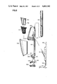
FIG. 3 is a side view of the vacuum cleaner of FIG. 1;
FIG. 4 is an enlarged bottom view of a portion of the vacuum cleaner of FIG. 1;
FIG. 5 is a top perspective view of the vacuum cleaner of FIG. 1, with the filter assembly canister partially removed;
FIG. 6 is an exploded view of the vacuum cleaner of FIG. 1;
FIG. 7 is a side view of the frame of the vacuum cleaner of FIG. 1;
FIG. 8 is a longitudinal cross sectional view of the housing of the frame;
FIG. 9 is an enlarged longitudinal view of a portion of the forward end or mounting assembly of the frame housing;
FIG. 10 is a top view of the portion of the frame housing illustrated in FIG. 9;
FIG. 11 is a transverse cross sectional view taken along the lines 11--11 of FIG. 10;
FIG. 12 is a top view of the lower nozzle section of the vacuum cleaner;
FIG. 13 is a cross sectional view of the lower nozzle section taken along the lines 13--13 of FIG. 12;
FIG. 14 is an enlarged cross sectional view of a forward wheel assembly taken along the lines 14--14 of FIG. 12;
FIG. 15 is a side view of the lower nozzle section in the direction indicated by the lines 15--15 of FIG. 12;
FIG. 16 is a transverse cross sectional view of the lower nozzle section taken along the lines 16--16 of FIG. 12;
FIG. 17 is a transverse cross sectional view of the lower nozzle section taken along the lines 17--17 of FIG. 12;
FIG. 18 is a bottom view of the lower nozzle section;
FIG. 19 is a rear view of the lower nozzle section;
FIG. 20 is a front view of the upper nozzle section of the vacuum cleaner;
FIG. 21 is a top view of the upper nozzle section;
FIG. 22 is a longitudinal cross sectional view of the upper nozzle section taken along the lines 22--22 of FIG. 21;
FIG. 23 is a bottom view of the upper nozzle section;
FIG. 24 is an end view of the upper nozzle section;
FIG. 25 is a transverse cross sectional view of the upper nozzle section taken along the lines 25--25 of FIG. 21;
FIG. 26 is a perspective view of the filter assembly of the vacuum cleaner;
FIG. 27 is a longitudinal cross sectional view of the cannister of the filter assembly;
FIG. 28 is an exploded partially cross sectional view of the filter assembly;
FIG. 29 is a side view of the canister;
FIG. 30 is a bottom view of the canister;
FIG. 31 is a rear view of the bag support;
FIG. 32 is a rear view of the bag holder ring;
FIG. 33 is a top view of the canister;
FIG. 34 is a rear end view of the canister, as seen along the lines 34--34 of FIG. 33;
FIG. 35 is a front end view of the canister, as seen along the lines 35--35 of FIG. 33;
FIG. 36 is a front view of the charging mount of the vacuum cleaner;
FIG. 37 is a side view of the charging mount;
FIG. 38 is a bottom view of the charging mount;
FIG. 39 is a top view of the charging mount housing;
FIG. 40 is a rear view of the charging mount housing;
FIG. 41 is a vertical cross sectional view of the charging mount housing taken along the lines 41--41 of FIG. 40 and including the connector thereof;
FIG. 42 is an enlarged cross sectional view of the charging mount housing taken along the lines 42--42 of FIG. 37;
FIG. 43 is an upper end view of the mounting projection of the charging mount, taken in the direction of the lines 43--43 of FIG. 37;
FIG. 44 a longitudinal cross sectional view of the assembled vacuum cleaner; and
FIG. 45 is a circuit diagram of the vacuum cleaner.
DETAILED DISCLOSURE OF THE INVENTION
Referring now to the drawings, and more in particular to FIGS. 1-6, therein is illustrated a vacuum cleaner system in accordance with the invention. The assembly is comprised of a frame 100 having a power assembly 200 on one end and a mounting assembly 300 on its other end for pivotally holding a nozzle assembly 400 comprised of an upper nozzle section 500 and a lower nozzle section 600. A filter assembly 7000 is adapted to be removably snapped to the frame, between the mounting assembly 300 and the power assembly 200, a filter bag 750 being mounted in the filter assembly 700 and being held in shape therein by a bag support 760. A handle 800 is affixed to the frame 100, for example in the power assembly 200 thereof. A charging mount 900, for example adapted to be mounted to a wall 980, has a mounting projection 901 adapted to be received in a recess 201 of the power assembly, thereby to enable the vacuum cleaner assembly to be hung on a wall and simultaneously charged. As will be discussed, suitable electrical connections are provided in the mounting projection 901 and in power assembly 200 in order to enable charging of the batteries of the power assembly when it is not in use.
As is readily apparent in the exploded diagram of FIG. 6 and the cross sectional view of FIG. 44, the power assembly, which includes a vacuum pump 200 is adapted to draw air through the nozzle assembly 400, thence through the mounting assembly 300 into the filter assembly 700. The air is drawn through the filter bag of the filter assembly, exiting into the vacuum pump 210 in the power assemby. Dirt drawn through the vacuum cleaner nozzle will hence collect on the outside of the filter bag and in the filter assembly canister. In order to discard such dirt, the filter assembly 700 may be readily disassembled from the frame. For example, as illustrated in the FIG. 5, upon depression (i.e. drawing toword the rear) of a latch button 202, the rear of the filter asesmbly 700 may be pivoted away from the frame, the forward end thereof being formed to pivot in the mounting assembly 300.
As employed hereafter in this disclosure, the terms "rearwardly" or "rear" side, refer to the direction toword the handle, whereas the "forward" direction refers to the direction towards the nozzle assembly.
The frame of the vacuum cleaner in accordance with the invention is illustrated in more detail in FIGS. 7-11. The frame is preferably molded from a high impact plastic of conventional material, and may be formed in two longitudinal halves adapted to be held together by any conventional means, such as screws.
The frame 100 may be comprised of a generally bar-shaped support 101. The mounting assembly 300 is comprised of a hollow base 301 affixed to one end of the bar-shaped support 101, the rearward side 302 of the base 301 being inclined to the longitudinal direction of the bar-shaped support 101. For example, an angle A of about 30 degrees may be provided between the plane of the side 302 of the base and the perpendicular to the longitudinal direction of the bar-shaped support 101.
The upper surface 102 of the bar-shaped support 101 is generally planar, the base 301 of the mounting assembly defining a rearwardly extending rim 303 about its periphery and terminating at the bar-shaped support 101 in the plane of the surface 102. As will be apparent in the following discussion of the filter assembly, the rim 303 of the mounting assembly serves to hold and provide a pivot surface for the filter assembly, the filter assembly being formed to laterally surround the bar-shaped support 101 to laterally support the filter assembly in an esthetic manner. As employed herein the term "upper" refers to the direction away from the side of the vacuum cleaner adapted to be adjacent a mounting wall when the vacuum cleaner is held on the wall mounted charging mount 900.
A hollow pivot cylinder 310 is affixed to the front side of the base 301 by a forwardly extending mounting stub 311. The axis of the pivot cylinder extends transversely of the vacuum cleaner, i.e., normal to a vertical longitudinal plane extending through the vacuum cleaner, the term "vertical" referring of course to a plane extending in the upward direction as above defined. The pivot cylinder has end walls 320,321 joined by an upper partial circumferential wall 322 and a lower partial cicumferential wall 323. The forward cicumferential gap 324 between the circumferential walls 322 and 323 defines a passageway for air, from the forward end of the mounting assembly through the rear end thereof. The rear ends of the walls 320 and 321 and partial circumferential walls 322 and 323 of the pivot cylinder are rearwardly extended through the stub 311, to laterally enclose the defined passageway laterally. An axially extending annular projection 340 is provided depending from the outside of each end wall 320,321, for serving as a labyrinth seal with the nozzle assembly, and to provide a pivoting surface, as will be discussed.
In order to hold the longitudinal halves of the frame assembly together, suitable screw holes may be provided therein such as the screw hole 350 of the pivot cylinder, the screw holes 110 on the bar shaped element, and the screwholes 290 in the power assembly, each adapted to receive a self-tapping screw (not shown).
The pivot cylinder 310 is adapted to pivotally mount the nozzle assembly to the vacuum cleaner, and sealingly direct air from the nozzle assembly to the filter assembly. The nozzle assembly is illustrated in detail in FIGS. 12-25, FIGS. 12-19 illustrating the lower nozzle section and FIGS. 20-25 illustrating the upper nozzle section.
As illustrated in FIGS. 12-19, the lower nozzle section is comprised of a moulded plastic shell 610 having a lower surface 611 and an upwardly extending rim 612 depending therefrom. As illustrated in FIGS. 20-25, the upper nozzle section is comprised of a moulded plastic shell 510 having an upper surface 511 and a downwardly extending rim 512 depending thereform, the rim 512 of the upper nozzle section being adapted to vertically abut the top of the rim 612 of the lower nozzle section. The upper and lower nozzle sections are adapted to be held together by any conventional means, such as screws. For this purpose, downwardly extending studs 520 of the upper nozzle section are adapted to abut the top of the bottom surface of the lower nozzle section adjacent recessed holes 620 of the lower nozzle section when the upper and lower nozzle sections are assembled together, so that suitable screws (not shown) extending through the recessed holes 620 may be threaded into the studs 520.
The shells which form the upper and lower nozzle sections are generally rectangular, with the longer dimension thereof extending transversly of the vacuum cleaner, i.e., in the direction of the axis of the pivot cylinder 320 of the mounting assembly 300.
The molding shell 610 has a pair of generally rectangular apertures 630 extending therethrough adjacent its forward edge 632, the apertures being symmetrically located on opposite sides of the center of the bottom (i.e. the axial center of the pivot cylinder 310 of the mounting assembly 300, when the nozzle is assembled thereto). As seen in FIG. 14, a pair of short walls 632 are provided extending upwardly adjacent the sides of each of the recesses 630, the upper surface of the walls 632 each having a transversly extending groove for receiving the shaft 635 of a forward wheel 636, the forward wheels having a diameter to extend through the apertures 630 to serve as floor engaging wheels. Axial displacement of the forward wheels is prevented by projections 637 extending upwardly from the bottom of the bottom surface 610, to axially abut the shaft 635 at each end. The shaft 635 is vertically retained in the grooves in the walls 632 by downwardly extending short walls 530 of the upper nozzle section (FIGS. 20-25), the bottom end of the short walls 530 abutting the tops of the short walls 632 of the lower nozzle section.
A generally rectangular rear extension 640 is provided on the lower nozzle section for receiving the rear roller wheels 641. The bottom surface of the rear extension 640 is generally alined with the bottom 610. The rear extension 640 has a pair of rectangular recesses 642 extending upwardly from its bottom surface, on opposite sides of the center of the lower nozzle section, the recesses (which preferably have closed tops) receiving the rear roller wheels 641. The shafts 643 of the roller wheels 641 extend into side recesses 644 of the recess 642, the recesses 644 being peened over or otherwise deformed so that the shafts 643 may be inserted thereinto and held during use of the vacuum cleaner.
In order to pivotally mount the nozzle on the pivot cylinder 310 of the mounting assembly (FIGS. 7-11), a pair of walls 650 are provided extending upwardly from the bottom 610 of the lower nozzle section, and symmetrically on opposite sides of the center thereof and adjacent the rear 651 thereof, the walls 650 extending above the top of the rim 612 and having semicircular recesses 652 in their upper surfaces, substantially equal in diameter to the diameter of the annular projections 340 of the pivot cylinder 310 of the mounting assembly 300 of FIGS. 7-11. These walls 650 are spaced apart a distance so that when the nozzle is assembled on the pivot cylinder, the circumferences of the annular projections 340 engage the semicircular recesses 652. Corresponding downwardly extending walls 550 are provided on the upper nozzle section (FIGS. 20-25), the walls 550 having semicircular recesses 551 in their lower edges for engaging the circumferences of the annular projections 340 of the pivot cylinder. The bottoms of the walls 550 are positioned to engage the top surfaces of the walls 650, so that the semicircular recesses of the walls 650 and 550 substantially completely surround the annular projection 340 of the pivot cylinder to hold the nozzle assembly and mounting assembly together and to permit limited pivoting movement of the nozzle assembly. Since the walls 650 of the lower nozzle portion extend above the lower nozzle section as seen in FIG. 16, the center of the upper nozzle section has a raised boss 560, from which the walls 550 extend downwardly. The rear of the boss 560 has a recess 551 cut out therefrom to enable the stub 311 of the pivot cylinder to pass therethrough, and to permit the pivotal movement of the nozzle assembly. On assembly of the nozzle assembly to the pivot cylinder, the upper nozzle section is first assembled onto the pivot cylinder, after which the bottom nozzle section is affixed to the upper nozzle section. Since the annular projections 340 extend to engage the semicircular recesses of the nozzle sections, the nozzle cannot be removed from the mounting assembly without first separating the upper and lower nozzle sections.
Referring again to FIGS. 12-19, the lower surface 601 of the bottom nozzle section has an upwardly extending recess 660, the recess 660 having a central portion 661 extending transversely of the vacuum cleaner and terminating at and portions 662 extending to the front corners 663 of the lower nozzle section. An aperture 668 extends through the bottom of the nozzle section, to enable communication between recess 660 and the passageway 324 through the pivot cylinder 310. Since the power assembly of the vacuum cleaner is drawing air from the nozzle through the filter, it is apparent that the recess 660 forms a channel creating a flow path from the front corners of the nozzle. This channel enhances the ability of the nozzle to pick up dirt at the corners of the nozzle, it being apparent of course that, since the recess 660 extends across the entire bottom nozzle section, dirt is picked up by the nozzle throughout its width, as the nozzle is moved across the surface to be cleaned.
In order to inhibit the flow of air into the pivot cylinder from the other portions of the nozzle, the lower nozzle portion is further provided with walls 670 spaced from the outside of the walls 650, the upper nozzle section being provided with corresponding downwardly extending walls 570 adapted to abut the walls 670. The walls 570 and 670 hence inhibit the flow of air axially to the pivot cylinder from the interior of the nozzle. The lower and upper nozzle sections are preferably provided with seals 670 and 570 respectably for engaging the pivot cylinder, to inhibit the escape of air through the rotating pivot joint. For example, the lower and upper nozzle sections may be provided with suitably shaped surfaces for holding seals 665,565 to engage the end portions 320,321 of the pivot cylinder as well as transversely extending seal portions 666 positioned to abut the arcuate wall portions 323 and 322 respectively of the pivot cylinder.
Referring now to FIGS. 7, 8 and 44, the power assembly 200 is comprised of a housing 204 affixed to the rear of the bar-shaped support 101, for enclosing the vacuum pump and electrical control circuits. The housing 204 has an upwardly extending central front wall 205 with a central hole 203 for receiving air from the filter assembly. The wall 205 extends generally perpendicular to the plane of the top surface 102. The outer portions of the front of the housing 204 are defined by a wall 206 inclined to the plane of the top surface 102 and away from the mounting assembly to enable receiving the seal of the filter assembly as will be discussed later. The inner edge of the wall 206 is joined to the vertical wall 205.
A vacuum pump 210 is mounted immediately behind the wall 205, as illustrated in FIG. 44, for receiving air through the hole 203 and ejecting it through side ports 207 of the housing 204. A motor 208 drives the vacuum pump, and is mounted to the rear of the vacuum pump. An operating switch 209 is mounted in the housing 204, having an actuator 211. A plastic button 212 engages the actuator 211 and is slidably mounted in a suitable slot in the housing wall. Suitable support walls 213 are provided in the housing for holding a rechargeable battery 214, such as a Nicad battery. A charging lamp 215, such as a LED, is mounted on the top of the housing 204, to provide an indication of charging of the battery. A connector 216 is mounted in the the bottom of the recess 201, for engaging a mating connector 905 in the charging mount (FIG. 41). A circuit board 217 is mounted within the housing 204 at the rear of the connector 216, to carry further electrical components of the circut. Thus, as illustrated in FIG. 45, the switch 211 is connected to enable the application of current from the battery 214 to the motor 208. The charging circuit is comprised of a rectifier 230 connected between one of the terminals of the connector 216 and one terminal of the battery 214, the other terminal of the connector 216 being connected directly to the other terminal of the battery. It will be apparent that the voltage applied to the connector 216 is an AC voltage, and is stepped down by the wall socket transformer 925 connected to the charging mount, as illustrated in FIG. 6. The charging indicating lamp 215 is connected to the connector 216 by way of a dropping resister 240 and diode 241, for limiting the indicator current and blocking reverse voltage on the indicator lamp.
The filter assembly is illustrated in FIGS. 26-35 and 44. As illustrated, the filter assembly is comprised of a hollow canister 701 having a forward end 702 and a rear end 703. The forward end 702 is shaped to fit into the rim 303 of the mounting assembly, as illustrated in FIGS. 6 and 44, to abut the seal 380 surrounding the passage way 324 of the mounting assembly. The rear end 703 of the canister is inclined to the plane of the surface 102, so that it may sealingly engage the inclined forward end 206 of the power assembly. The canister further has a lontitudinally extending resess 704 in its bottom, to receive the frame 100.
The canister of the filter assembly is installed on the vacuum cleaner by inserting the forward end into the rim 303 of the mounting assembly, and then pivoting the rear of the canister downwardly until its inclined rear surface abuts the inclined forward surface 206 of the power assembly. In this position, the longitudianl recess 704 of the canister receives the frame 100, to inhibit any side wise movement of the canister with respect to the mounting assembly and power assembly. Further, as apparent in FIGS. 2-4, when the canister is thus installed, the bottom of the frame is flush with the bottom of the canister, to form a smooth esthetic appearance. The pivoting of the canister, during the assembly is illustrated in FIG. 5.
In order to hold the canister in position in the vacuum cleaner assembly, the catch 202 on the rear end of the top of the power assembly slidingly engages a lip 705 extending rearwardly from the top of the rear surface 703 of the canister. The catch 202 is urged forwardly by a spring 203 provided in a suitable resess in the power assembly housing 204, as illustrated in FIGS. 8 and 44. Consequently, manually urging the catch 202 enables release of the canister, so that it may be pivoted away from and removed from the vacuum cleaner. Since the forward end of the canister pivots in the mounting assembly, the inclined rear edge of the canister meets the inclined forward surface 206 of the power assembly at the position where the catch 202 engages the projection 705 of the canister, to lock the canister in place.
As illustrated more clearly in FIGS. 27 and 28, the forward end 702 of the canister communicates with the interior of the canister by way of a longitudinally extending port 706 which extends a short distance into the canister. A flap valve 707 is mounted on the rear end of the port 706. The flap valve may be comprised, for example, of a flexible plastic or rubber sheet affixed, for example, to the bottom of the rear of the port 706. The flap valve 707 permits flow of air rearwardly through the port 706 and into the canister, but inhibits the flow of air in the reverse direction.
The filter bag assembly 750 is comprised of a bag holding ring 751 and a filter bag 752. The holding ring 751 is shaped to fit within the front end 703 of the canister, and be supported against the front edges of 711 of longitudinally extending ribs 712, their front edges 711 being set back from the front edge 703. The holding ring 751 has a rearwardly extending flange 753 over which the front end of the filter bag 752 extends and is held by any conventional means. The bag 752 thus extends into the cannister 701. The ring 751 is sufficiently rigid to hold the bag 752, and has a flexible sealing lip 754 extending around its forward surface, to form a seal against the inclined surface 206 of the power assembly.
The holding ring 751, which may be of plastic or rubber material, further has a recess 755 adjacent its forward end for receiving and holding the forward rim 761 of the bag support 760, as illustrated in FIG. 44. The bag support 760 defines a forwardly extending cage 765, extending into the bag 752, to hold the shape of the bag, as illustrated for example in FIG. 44. The filter bag assembly 750 may be removed from the canister for cleaning, as illustrated in FIG. 26. Thus, in order to remove dirt that has accumulated on the front of the filter bag during use, the canister is first removed from the vacuum cleaner by releasing it by means of the catch 202, and pivoting it out and away from the vacuum cleaner. The filter bag assembly 750 is then withdrawn from the front of the canister along with the bag support 760 held therein, and the dirt then shaken from the outside of the bag and from the interior of the canister into a suitable waste receptacle. The bag assembly may then be rassembled in the canister, and the canister reassembled on the vacuum cleaner as discussed above.
The charging mount, for supporting the vacuum cleaner when not in use, while simultaneously recharging the batteries therein, is illustrated in FIGS. 36-43. The charging mount which may be formed of a molded plastic material, has a base 910 adapted to be mounted to a wall, for example by means of screw holes 911. The mounting projection 901 extends upwardly at an angle from the base, and is shaped to be received in the similarly inclinedmounting ressess 201 of the power assembly. The connector 905 is held within the mounting projection 901, as illustrated in FIG. 41, for example in a suitably shaped resses in an interior wall 914 of the mounting projection. The connector 905 is connected in conventional manner to the wall transformer 925 (FIG. 6) by way of cord 927.
An internal circuit that may be employed in the vacuum cleaner of the invention is illustrated in FIG. 45, wherein it is seen that the motor 208 is connected to the rechargeable battery 214 by way of the operating switch 211. The recharging terminals 216, to which the output of the recharging transformer 925 is applied, are connected to opposite terminals of the battery 214 by way of charging rectifier 230, so that the battery may be continually charged when the vacuum cleaner is mounted on the charging mount. The charging of the battery is indicated by the LED indicator 215, connected to the terminals 216 by way of the rectifier 241 and dropping resister 240.
While the invention has been disclosed and described with reference to a single embodiment, it is apparent that variations and modifications may be made therein, and is therefore intended in the following claims to cover each such variation and modification as falls within the true spirt and scope of the invention.

Claims (19)

What is claimed is:
1. In a vacuum cleaner assembly comprising a hollow nozzle assembly, a vacuum pump, a filter, and means for directing air from said nozzle assembly to said pump by way of said filter bag, the improvement wherein said vacuum cleaner assembly further comprises a mounting frame, a mounting arrangement for mounting said pump and nozzle assembly in spaced apart relationship to said mounting frame, and said directing means comprises a canister removably mounted to said mounting frame between said nozzle assembly and pump and having a longitudinal recess extending along one edge thereof, said filter bag being removably held in said canister, said mounting frame extending in said recess and inhibiting relative rotation of said canister about its longitudinal axis.
2. The vacuum cleaner of claim 1 wherein said directing means further comprises a hollow mounting assembly mounted on said frame, and said nozzle assembly is pivotally mounted on said mounting assembly, whereby air from said nozzle assembly passes through said hollow mounting assembly.
3. In a vacuum cleaner assembly comprising a hollow nozzle assembly, a vacuum pump, a filter bag, and means for directing air from said nozzle assembly to said pump by way of said filter bag, the improvement wherein said vacuum cleaner assembly further comprises a mounting frame, a mounting arrangement for mounting said pump and nozzle assembly in spaced apart relationship to said mounting frame, and said directing means comprises a canister removably mounted to said mounting frame between said nozzle assembly and pump, said filter bag being removably held in said canister, said directing means further comprising a hollow mounting assembly mounted on said frame, said nozzle assembly being pivotally mounted on said mounting assembly, whereby air from said nozzle assembly passes through said hollow mounting assembly, one end of said canister being removably received in a recess in said hollow mounting assembly, and further comprising a power assembly housing containing said vacuum pump, and a latching arrangement on said power assembly housing positioned to releasably hold said canister to said mounting frame, whereby upon release of said latching arrangement said canister may be removed from said recess by rotating said end of said canister with respect to said mounting assembly.
4. A portable vacuum cleaner comprising a frame, a hollow mounting arrangement and a power assembly fixedly mounted in spaced apart relationship on said frame, said power assembly including a vacuum pump, a filter assembly including a canister having a longitudinal recess extending along one side thereof, said canister being removably fitted between said mounting arrangement and said power assembly with said frame extending in said recess whereby said vacuum pump draws air through said mounting arrangement means and canister to said vacuum pump when said canister is fitted between said mounting arrangement and power assembly, and a hollow nozzle mounted on said mounting arrangement.
5. The portable vacuum cleaner of claim 4 wherein said nozzle is mounted on said mounting arrangement for limited pivotal movement.
6. The portable vacuum cleaner of claim 4 wherein said mounting arrangement comprises a mounting cylinder having a duct extending transversely therethrough, and said nozzle is pivotally held on said mounting cylinder, whereby air from said nozzle is directed through said cylinder to said vacuum pump.
7. The portable vacuum cleaner of claim 6 wherein said nozzle is comprised of upper and lower nozzle sections fitted together around said mounting cylinder, and each having arcuate sealing surfaces engaging said mounting cylinder.
8. The portable vacuum cleaner of claim 4 wherein said frame comprises an elongated support, said mounting arrangement comprising a hollow element on one end of said elongated support, said power assembly comprising a power assembly housing on the other end of said elongated support.
9. The portable vacuum cleaner of claim 8 wherein said power assembly housing has an end facing said mounting arrangement that is inclined to the longitudinal direction of said elongated support and away from said mounting arrangement.
10. The portable vacuum cleaner of claim 9 wherein at least a portion of one end of said canister is removably received in a recess in the end of said mounting arrangement facing said power assembly and has an end face sealingly engaging said end of said power assembly.
11. The portable vacuum cleaner of claim 8 wherein one end of said canister longitudinally engages a recess in the end of said mounting arrangement facing said power assembly, further comprising a latching arrangement holding the other end of said canister to said power assembly.
12. The portable vacuum cleaner of claim 11 further comprising a filter bag removably held in said other end of said canister, said filter bag having a seal engaging said power assembly.
13. The portable vacuum cleaner of claim 12 wherein said canister further includes a flap valve mounted to inhibit flow of air in the direction away from said vacuum pump.
14. The portable vacuum cleaner of claim 4 wherein said hollow nozzle has a lower surface adapted to be drawn across a surface to be cleaned, and a recess extending transversely across said lower surface, said nozzle further having a duct extending from said recess to said hollow mounting arrangement.
15. The portable vacuum cleaner of claim 14 wherein said lower surface of said nozzle has front corners, and said recess extends adjacent said front corners.
16. The portable vacuum cleaner of claim 14 wherein wheels are mounted in said lower surface for engaging a surface to be cleaned.
17. The portable vacuum cleaner of claim 4 wherein said power assembly comprises a housing, a mounting recess in said housing for receiving a mounting projection to enable mounting said vacuum cleaner on a wall, said vacuum pump including a motor, a battery for energizing said motor, a charging circuit for charging said battery, and a connector in said recess and connected to said charging circuit for enabling charging of said battery.
18. In a vacuum cleaner assembly comprising a hollow nozzle assembly, a vacuum pump, a filter bag, and means for directing air from said nozzle assembly to said pump by way of said filter bag, the improvement wherein said vacuum cleaner assembly further comprises a mounting frame, a mounting arrangement for mounting said pump and nozzle assembly in spaced apart relationship to said mounting frame, said directing means comprising a canister removably mounted to said mounting frame between said nozzle assembly and pump, said filter bag being removably held in said canister, said nozzle assembly being pivotally mounted to said mounting arrangement and having a lower surface, a duct forming part of the directing means and extending centrally through said lower surface and communicating with said canister by way of said mounting assembly, at least one ground engaging wheel having a fixed axis and mounted forwardly of said duct, and at least one ground engaging wheel having a fixed axis and mounted rearwardly of said duct, the axis of pivoting of said nozzle being parallel to and in a vertical plane between the axis of the wheels, said nozzle assembly comprising upper and lower nozzle portions, said lower surface being the lower surface of said lower nozzle portion, said mounting arrangement comprising a mounting cylinder having a transversely extending port, said upper and lower nozzle portions having semicylindrical surfaces rotatably engaging said mounting cylinder for pivotally mounting said nozzle on said mounting cylinder with said duct communicating with said port.
19. A portable vacuum cleaner comprising a frame, a hollow mounting arrangement and a power assembly fixedly mounted in spaced apart relationship on said frame, said power assembly including a vacuum pump, a filter assembly including a canister removably fitted between said mounting assembly and said power assembly whereby said vacuum pump draws air through said mounting arrangement and canister to said vacuum pump when said canister is fitted between said mounting arrangement and power assembly, a hollow nozzle mounted on said mounting arrangement, said mounting arrangement having a rearwardly extending rim defining a recess for receiving the forward end of said canister, said power assembly having a forward surface for engaging the rear end of said canister that is inclined to the longitudinal axis of said cleaner, a latch mounted to releasably hold the rear end of said canister to said power assembly, whereby said canister may be removed from said vacuum cleaner by release of said latch and rotational movement of the canister in one direction with respect to said recess, and means inhibiting removal of said canister from said vacuum cleaner in all other directions.
US06/704,567 1985-02-22 1985-02-22 Lightweight battery powered suction broom Expired - Lifetime US4665582A (en)

Priority Applications (10)

Application Number Priority Date Filing Date Title
US06/704,567 US4665582A (en) 1985-02-22 1985-02-22 Lightweight battery powered suction broom
AU52876/86A AU574260B2 (en) 1985-02-22 1986-01-31 Vacuum cleaner
NO860368A NO168455C (en) 1985-02-22 1986-02-03 EASY BATTERY DUST Vacuum Cleaner.
NZ215179A NZ215179A (en) 1985-02-22 1986-02-17 Lightweight vacuum cleaner assembly
AT86850055T ATE47294T1 (en) 1985-02-22 1986-02-19 LIGHT BATTERY OPERATED VACUUM CLEANER.
DE8686850055T DE3666333D1 (en) 1985-02-22 1986-02-19 Lightweight battery powered suction broom
EP86850055A EP0192624B1 (en) 1985-02-22 1986-02-19 Lightweight battery powered suction broom
DK83286A DK83286A (en) 1985-02-22 1986-02-21 LIGHT-BATTERY BATTERY VACUUM COST
FI860777A FI84227C (en) 1985-02-22 1986-02-21 BAERBAR DAMMSUGARE.
JP61036547A JPS61196928A (en) 1985-02-22 1986-02-22 Vacuum cleaner

Applications Claiming Priority (1)

Application Number Priority Date Filing Date Title
US06/704,567 US4665582A (en) 1985-02-22 1985-02-22 Lightweight battery powered suction broom

Publications (1)

Publication Number Publication Date
US4665582A true US4665582A (en) 1987-05-19

Family

ID=24830038

Family Applications (1)

Application Number Title Priority Date Filing Date
US06/704,567 Expired - Lifetime US4665582A (en) 1985-02-22 1985-02-22 Lightweight battery powered suction broom

Country Status (10)

Country Link
US (1) US4665582A (en)
EP (1) EP0192624B1 (en)
JP (1) JPS61196928A (en)
AT (1) ATE47294T1 (en)
AU (1) AU574260B2 (en)
DE (1) DE3666333D1 (en)
DK (1) DK83286A (en)
FI (1) FI84227C (en)
NO (1) NO168455C (en)
NZ (1) NZ215179A (en)

Cited By (56)

* Cited by examiner, † Cited by third party
Publication number Priority date Publication date Assignee Title
US4920606A (en) * 1989-01-09 1990-05-01 Black & Decker, Inc. Electrical power circuit for a vacuum cleaner
US4928347A (en) * 1989-01-09 1990-05-29 Black & Decker Inc. Vacuum cleaner dust bowl latch and release system
US4934020A (en) * 1989-01-09 1990-06-19 Black & Decker Inc. Charging unit and vacuum cleaner
US4942641A (en) * 1989-01-09 1990-07-24 Black & Decker Inc. Accessory brush attachment
US4947514A (en) * 1989-01-09 1990-08-14 Black & Decker, Inc. Internal contact for a charging circuit
US4967443A (en) * 1989-01-09 1990-11-06 Black & Decker, Inc. Filter assembly for a vacuum cleaner
US5337443A (en) * 1992-07-21 1994-08-16 Bissell Inc. Vacuum cleaner
US5524321A (en) * 1994-02-14 1996-06-11 Bissell Inc. Vacuum Cleaner with a detachable vacuum module
US5638572A (en) * 1995-01-24 1997-06-17 Brain Wave S.R.L. Electric broom
US5671499A (en) * 1996-01-11 1997-09-30 Black & Decker Inc. Vacuum cleaner with all components in floor traveling head
US5715566A (en) * 1993-02-12 1998-02-10 Bissell Inc. Cleaning machine with a detachable cleaning module
US5819364A (en) * 1992-09-09 1998-10-13 Pentalpha Enterprises, Ltd. Detachable handle accessory for a portable steam vacuum cleaner
US5869947A (en) * 1995-01-13 1999-02-09 Royal Appliance Mfg. Co. Rechargeable hand held vacuum cleaner with electrical connections circuit board with spring contacts
USD421671S (en) * 1998-01-09 2000-03-14 White Consolidated Industries, Inc. Vacuum cleaner
US6108864A (en) * 1998-01-09 2000-08-29 White Consolidated Industries, Inc. Vacuum cleaner having a reusable dirt cup
USD433201S (en) * 1999-01-06 2000-10-31 Royal Appliance Mfg. Co. Vacuum cleaner dust cup
EP1070478A2 (en) * 1999-07-17 2001-01-24 Black & Decker Inc. Vacuum cleaner
US6243912B1 (en) * 1996-02-22 2001-06-12 Vax Limited Apparatus for cleaning floors, carpets and the like
US6334234B1 (en) * 1999-01-08 2002-01-01 Fantom Technologies Inc. Cleaner head for a vacuum cleaner
US6353963B1 (en) * 1998-01-09 2002-03-12 Royal Appliance Mfg. Co. Upright vacuum cleaner with cyclonic air flow
US6385810B1 (en) * 2000-05-05 2002-05-14 The Hoover Company Latch arrangement for a vacuum cleaner dirt receptacle
US6463622B2 (en) 1998-01-09 2002-10-15 Royal Appliance Mfg. Co. Upright vacuum cleaner with cyclonic airflow
US20030037405A1 (en) * 2001-02-06 2003-02-27 Moine David W. Dirt collecting system for a floor care appliance
US6536072B2 (en) * 2001-01-11 2003-03-25 Royal Appliance Mfg. Co. Compression latch for dirt cup
US20030145427A1 (en) * 2002-02-06 2003-08-07 Royal Appliance Mfg. Co. Floor nozzle for a vacuum cleaner
US20040034962A1 (en) * 2002-08-20 2004-02-26 Royal Appliance Mfg. Co. Vacuum cleaner having hose detachable at nozzle
US20040068828A1 (en) * 1998-01-09 2004-04-15 Royal Appliance Mfg. Co. Upright vacuum cleaner with cyclonic air flow
US20040088820A1 (en) * 1998-07-06 2004-05-13 Tomonori Kato Vacuum cleaner
US6740144B2 (en) 1999-01-08 2004-05-25 Fantom Technologies Inc. Vacuum cleaner utilizing electrostatic filtration and electrostatic precipitator for use therein
US6745432B2 (en) 1998-01-09 2004-06-08 Royal Appliance Mfg. Co. Upright vacuum cleaner with cyclonic airflow
US20040134016A1 (en) * 2003-01-10 2004-07-15 Royal Appliance Manufacturing Company Suction wet jet mop
US20040134025A1 (en) * 2003-01-10 2004-07-15 Royal Appliance Mfg. Co. Vacuum cleaner with cleaning pad
US20040134022A1 (en) * 2003-01-10 2004-07-15 Royal Manufacturing Co. Bagless stick type vacuum cleaner
US6775882B2 (en) 2002-01-11 2004-08-17 Royal Appliance Mfg. Co. Stick vacuum with dirt cup
US6782585B1 (en) 1999-01-08 2004-08-31 Fantom Technologies Inc. Upright vacuum cleaner with cyclonic air flow
US20050076468A1 (en) * 2003-10-09 2005-04-14 Royal Appliance Mfg. Co. Cleaning attachment for vacuum cleaner
WO2007032796A2 (en) 2005-06-10 2007-03-22 Electrolux Home Care Products North America Sodium bicarbonate vacuum bag inserts
US20070074371A1 (en) * 2005-10-04 2007-04-05 Samsung Gwangju Electronics Co., Ltd. Suction brush for a vacuum cleaner
US20070163073A1 (en) * 2006-01-19 2007-07-19 Arnold Sepke Vacuum cleaner dustcup and conduit construction
US20080040883A1 (en) * 2006-04-10 2008-02-21 Jonas Beskow Air Flow Losses in a Vacuum Cleaners
US20080263818A1 (en) * 2000-01-14 2008-10-30 Electrolux Home Care Products, Ltd. Upright Vacuum Cleaner with Cyclonic Air Path
WO2009079638A1 (en) * 2007-12-18 2009-06-25 Royal Appliance Mfg. Co. D/B/A Sweepable electric vacuum cleaner
US20090165239A1 (en) * 2006-03-24 2009-07-02 Thommy Frantzen Handheld Vacuum Cleaner
US20100017997A1 (en) * 2006-04-10 2010-01-28 Jonas Beskow Vacuum Cleaner
US20100083459A1 (en) * 2007-01-19 2010-04-08 Aktiebolaget Electrolux Air Flow Losses in Vacuum Cleaners
US20100218339A1 (en) * 2007-01-23 2010-09-02 Fahlstroem Johan Vacuum Cleaner Nozzle
US20100229337A1 (en) * 2009-03-13 2010-09-16 G.B.D. Corp. Surface cleaning head
US8225456B2 (en) 2003-02-10 2012-07-24 Ab Electrolux Hand held vacuum cleaner
US8424154B2 (en) 2006-04-10 2013-04-23 Ab Electrolux Vacuum cleaner with filter cleaning means
US20160198920A1 (en) * 2013-09-23 2016-07-14 Alfred Kärcher Gmbh & Co. Kg Suction nozzle apparatus for a cleaning device, and cleaning device
JP2017029409A (en) * 2015-07-31 2017-02-09 アイリスオーヤマ株式会社 Cleaner
USD789004S1 (en) 2015-04-27 2017-06-06 Alfred Kaercher Gmbh & Co. Kg Floor cleaning machine
US20190298135A1 (en) * 2017-03-03 2019-10-03 Lg Electronics Inc. Support device of cleaner and cleaner unit
USD875335S1 (en) 2018-03-13 2020-02-11 Alfred Kaercher Se & Co. Kg Steam cleaner
US10758101B2 (en) 2017-06-12 2020-09-01 Emerson Electric Co. Upright vacuum cleaner with battery support plate
US20230225574A1 (en) * 2018-08-13 2023-07-20 Omachron Intellectual Property Inc. Cyclonic air treatment member and surface cleaning apparatus including the same

Families Citing this family (5)

* Cited by examiner, † Cited by third party
Publication number Priority date Publication date Assignee Title
DE4042371A1 (en) * 1990-09-26 1992-04-02 Licentia Gmbh Battery-operated vacuum cleaner - has removable dust bag within dust collection space between air inlet duct and suction fan
DE4030347A1 (en) * 1990-09-26 1992-04-02 Licentia Gmbh Small accumulator operated vacuum cleaner - has extended housing consisting of rear housing part for motor fan and accumulators
SE532852C2 (en) * 2008-10-10 2010-04-20 Electrolux Ab dust container
DE102017209152A1 (en) * 2017-05-31 2018-12-06 BSH Hausgeräte GmbH Conveniently rechargeable hand-held battery operated vacuum cleaner
DE102017209157B4 (en) * 2017-05-31 2020-07-09 BSH Hausgeräte GmbH Wall bracket for a handheld vacuum cleaner

Citations (14)

* Cited by examiner, † Cited by third party
Publication number Priority date Publication date Assignee Title
US1759947A (en) * 1924-01-14 1930-05-27 Delco Light Co Domestic appliance
US1768617A (en) * 1924-01-14 1930-07-01 Delco Light Co Domestic appliance
US1826798A (en) * 1923-04-30 1931-10-13 Delco Light Co Domestic appliance
US2564339A (en) * 1950-05-06 1951-08-14 Lawrence F Nerheim Vacuum cleaner
US2626418A (en) * 1948-09-10 1953-01-27 Kingston Products Corp Nozzle casing for broom-type vacuum cleaners
US2658228A (en) * 1950-04-22 1953-11-10 Lewyt Corp Vacuum cleaner nozzle
US2954576A (en) * 1958-11-06 1960-10-04 Hoover Co Suction appliance
GB990065A (en) * 1961-02-15 1965-04-22 Licentia Gmbh Improvements in or relating to suction cleaners
US3273194A (en) * 1963-05-31 1966-09-20 Sunbeam Corp Vacuum cleaner
DE1453075A1 (en) * 1963-12-07 1969-02-06 Siemens Elektrogeraete Gmbh Hand vacuum cleaner
US3512208A (en) * 1968-04-01 1970-05-19 Haley Corp Adjustment means for tool brush in vacuum cleaner
US3758914A (en) * 1971-10-06 1973-09-18 Whirlpool Co Vacuum cleaner with movable handle structure
DE3228491A1 (en) * 1982-07-30 1984-02-09 Euras Elekt Forsch & Prod BATTERY-POWERED, RECHARGEABLE HAND VACUUM CLEANER
US4558484A (en) * 1984-03-02 1985-12-17 Regina Corporation Tank unit for cleaning devices

Family Cites Families (6)

* Cited by examiner, † Cited by third party
Publication number Priority date Publication date Assignee Title
DE2719397A1 (en) * 1977-04-30 1978-11-02 Licentia Gmbh Vacuum cleaner with easily removed dust bag - has holder for latter on removable lid which then acts as handle
US4209875A (en) * 1978-08-11 1980-07-01 Black & Decker, Inc. Cordless vacuum cleaner bowl and filter system
DE2932017A1 (en) * 1979-08-07 1981-02-26 Siemens Ag Adaptable handle type vacuum cleaner - has suction head attached to one pipe, steering handle to other pipe
US4307485A (en) * 1979-09-04 1981-12-29 Black & Decker Inc. Air-powered vacuum cleaner floor tool
DE2947994A1 (en) * 1979-11-28 1981-07-23 Düpro AG, Romanshorn ELECTRIC BRUSHES FOR VACUUM CLEANERS
GB2126471B (en) * 1982-09-16 1985-11-13 Hoover Plc Suction cleaners

Patent Citations (14)

* Cited by examiner, † Cited by third party
Publication number Priority date Publication date Assignee Title
US1826798A (en) * 1923-04-30 1931-10-13 Delco Light Co Domestic appliance
US1759947A (en) * 1924-01-14 1930-05-27 Delco Light Co Domestic appliance
US1768617A (en) * 1924-01-14 1930-07-01 Delco Light Co Domestic appliance
US2626418A (en) * 1948-09-10 1953-01-27 Kingston Products Corp Nozzle casing for broom-type vacuum cleaners
US2658228A (en) * 1950-04-22 1953-11-10 Lewyt Corp Vacuum cleaner nozzle
US2564339A (en) * 1950-05-06 1951-08-14 Lawrence F Nerheim Vacuum cleaner
US2954576A (en) * 1958-11-06 1960-10-04 Hoover Co Suction appliance
GB990065A (en) * 1961-02-15 1965-04-22 Licentia Gmbh Improvements in or relating to suction cleaners
US3273194A (en) * 1963-05-31 1966-09-20 Sunbeam Corp Vacuum cleaner
DE1453075A1 (en) * 1963-12-07 1969-02-06 Siemens Elektrogeraete Gmbh Hand vacuum cleaner
US3512208A (en) * 1968-04-01 1970-05-19 Haley Corp Adjustment means for tool brush in vacuum cleaner
US3758914A (en) * 1971-10-06 1973-09-18 Whirlpool Co Vacuum cleaner with movable handle structure
DE3228491A1 (en) * 1982-07-30 1984-02-09 Euras Elekt Forsch & Prod BATTERY-POWERED, RECHARGEABLE HAND VACUUM CLEANER
US4558484A (en) * 1984-03-02 1985-12-17 Regina Corporation Tank unit for cleaning devices

Cited By (115)

* Cited by examiner, † Cited by third party
Publication number Priority date Publication date Assignee Title
AU628272B2 (en) * 1989-01-09 1992-09-10 Black & Decker Incorporated Electrical power circuit for a vacuum cleaner
US4934020A (en) * 1989-01-09 1990-06-19 Black & Decker Inc. Charging unit and vacuum cleaner
US4942641A (en) * 1989-01-09 1990-07-24 Black & Decker Inc. Accessory brush attachment
US4928347A (en) * 1989-01-09 1990-05-29 Black & Decker Inc. Vacuum cleaner dust bowl latch and release system
US4947514A (en) * 1989-01-09 1990-08-14 Black & Decker, Inc. Internal contact for a charging circuit
US4967443A (en) * 1989-01-09 1990-11-06 Black & Decker, Inc. Filter assembly for a vacuum cleaner
AU616369B2 (en) * 1989-01-09 1991-10-24 Black & Decker Incorporated Vacuum cleaner dust bowl latch and release system
AU617075B2 (en) * 1989-01-09 1991-11-14 Black & Decker Incorporated Internal contact for a charging circuit
US4920606A (en) * 1989-01-09 1990-05-01 Black & Decker, Inc. Electrical power circuit for a vacuum cleaner
US5337443A (en) * 1992-07-21 1994-08-16 Bissell Inc. Vacuum cleaner
US5819364A (en) * 1992-09-09 1998-10-13 Pentalpha Enterprises, Ltd. Detachable handle accessory for a portable steam vacuum cleaner
US5715566A (en) * 1993-02-12 1998-02-10 Bissell Inc. Cleaning machine with a detachable cleaning module
US5524321A (en) * 1994-02-14 1996-06-11 Bissell Inc. Vacuum Cleaner with a detachable vacuum module
US5869947A (en) * 1995-01-13 1999-02-09 Royal Appliance Mfg. Co. Rechargeable hand held vacuum cleaner with electrical connections circuit board with spring contacts
US5638572A (en) * 1995-01-24 1997-06-17 Brain Wave S.R.L. Electric broom
US5671499A (en) * 1996-01-11 1997-09-30 Black & Decker Inc. Vacuum cleaner with all components in floor traveling head
US5765258A (en) * 1996-01-11 1998-06-16 Black & Decker Inc. Vacuum cleaner with all components in floor traveling head
US6243912B1 (en) * 1996-02-22 2001-06-12 Vax Limited Apparatus for cleaning floors, carpets and the like
US6588055B2 (en) 1998-01-09 2003-07-08 National City Bank Upright vacuum cleaner with cyclonic air flow
US20050028318A1 (en) * 1998-01-09 2005-02-10 Royal Appliance Mfg. Co. Upright vacuum cleaner with cyclonic air flow
US6944909B2 (en) 1998-01-09 2005-09-20 Royal Appliance Mfg. Co. Upright vacuum cleaner with cyclonic air flow
US6108864A (en) * 1998-01-09 2000-08-29 White Consolidated Industries, Inc. Vacuum cleaner having a reusable dirt cup
US20050183232A1 (en) * 1998-01-09 2005-08-25 Royal Appliance Mfg. Co. Upright vacuum cleaner with cyclonic airflow
US6353963B1 (en) * 1998-01-09 2002-03-12 Royal Appliance Mfg. Co. Upright vacuum cleaner with cyclonic air flow
US6901626B2 (en) 1998-01-09 2005-06-07 Royal Appliance Mfg. Co. Upright vacuum cleaner with cyclonic air flow
US6401295B2 (en) 1998-01-09 2002-06-11 Royal Appliance Mfg. Co. Upright vacuum cleaner with cyclonic air flow
US6463622B2 (en) 1998-01-09 2002-10-15 Royal Appliance Mfg. Co. Upright vacuum cleaner with cyclonic airflow
US20050091786A1 (en) * 1998-01-09 2005-05-05 Royal Appliance Mfg. Co. Upright vacuum cleaner with cyclonic airflow
US8001652B2 (en) 1998-01-09 2011-08-23 Techtronic Floor Care Technology Limited Upright vacuum cleaner with cyclonic airflow
USD421671S (en) * 1998-01-09 2000-03-14 White Consolidated Industries, Inc. Vacuum cleaner
US20050091787A1 (en) * 1998-01-09 2005-05-05 Royal Appliance Mfg. Co. Upright vacuum cleaner with cyclonic airflow
US20050217066A1 (en) * 1998-01-09 2005-10-06 Royal Appliance Mfg. Co. Upright vacuum cleaner with cyclonic air flow
US6588054B2 (en) 1998-01-09 2003-07-08 National City Bank Upright vacuum cleaner with cyclonic airflow
US6591446B2 (en) 1998-01-09 2003-07-15 Royal Appliance Mfg. Co. Upright vacuum cleaner with cyclonic air flow
USRE38949E1 (en) 1998-01-09 2006-01-31 Royal Appliance Mfg. Co. Upright vacuum cleaner with cyclonic airflow
US20050055796A1 (en) * 1998-01-09 2005-03-17 Royal Appliance Mfg. Co. Upright vacuum cleaner with cyclonic airflow
US20040068828A1 (en) * 1998-01-09 2004-04-15 Royal Appliance Mfg. Co. Upright vacuum cleaner with cyclonic air flow
US6857164B2 (en) 1998-01-09 2005-02-22 Royal Appliance Mfg. Co. Upright vacuum cleaner with cyclonic air flow
US6735815B2 (en) 1998-01-09 2004-05-18 Royal Appliance Mfg. Co. Upright vacuum cleaner with cyclonic air flow
US6735817B2 (en) 1998-01-09 2004-05-18 Royal Appliance Mfg. Co. Upright vacuum cleaner with cyclonic air flow
US6848146B2 (en) 1998-01-09 2005-02-01 Royal Appliance Mfg. Co. Upright vacuum cleaner with cyclonic airflow
US6745432B2 (en) 1998-01-09 2004-06-08 Royal Appliance Mfg. Co. Upright vacuum cleaner with cyclonic airflow
US20040205929A1 (en) * 1998-01-09 2004-10-21 Royal Appliance Mfg. Co Upright vacuum cleaner with cyclonic air flow
US7146681B2 (en) 1998-01-09 2006-12-12 Royal Appliance Mfg. Co. Upright vacuum cleaner with cyclonic airflow
US7134166B2 (en) 1998-01-09 2006-11-14 Royal Appliance Mfg. Co. Upright vacuum cleaner with cyclonic airflow
US7131165B2 (en) 1998-01-09 2006-11-07 Royal Appliance Mfg. Co. Upright vacuum cleaner with cyclonic airflow
US7117558B2 (en) 1998-01-09 2006-10-10 Royal Appliance Mfg. Co. Upright vacuum cleaner with cyclonic air flow
US7117557B2 (en) 1998-01-09 2006-10-10 Royal Appliance Mfg. Co. Upright vacuum cleaner with cyclonic air flow
US20040088820A1 (en) * 1998-07-06 2004-05-13 Tomonori Kato Vacuum cleaner
USD433201S (en) * 1999-01-06 2000-10-31 Royal Appliance Mfg. Co. Vacuum cleaner dust cup
US7179314B2 (en) 1999-01-08 2007-02-20 Polar Light Limited Vacuum cleaner
US20050028675A1 (en) * 1999-01-08 2005-02-10 Fantom Technologies Inc. Vacuum cleaner
US6740144B2 (en) 1999-01-08 2004-05-25 Fantom Technologies Inc. Vacuum cleaner utilizing electrostatic filtration and electrostatic precipitator for use therein
US6782585B1 (en) 1999-01-08 2004-08-31 Fantom Technologies Inc. Upright vacuum cleaner with cyclonic air flow
US20050177974A1 (en) * 1999-01-08 2005-08-18 Fantom Technologies Inc. Vacuum cleaner having two cyclonic cleaning stages
US6334234B1 (en) * 1999-01-08 2002-01-01 Fantom Technologies Inc. Cleaner head for a vacuum cleaner
EP1733670A1 (en) * 1999-07-17 2006-12-20 BLACK & DECKER INC. Improvements in vacuum cleaners
USRE40542E1 (en) 1999-07-17 2008-10-21 Black & Decker Inc. Dual filter vacuum cleaner apparatus
US6546592B1 (en) 1999-07-17 2003-04-15 Black & Decker Inc. Dual filter vacuum cleaner apparatus
EP1070478A3 (en) * 1999-07-17 2002-12-18 Black & Decker Inc. Vacuum cleaner
USRE43603E1 (en) * 1999-07-17 2012-08-28 Black & Decker Inc. Dual filter vacuum cleaner apparatus
EP1070478A2 (en) * 1999-07-17 2001-01-24 Black & Decker Inc. Vacuum cleaner
EP1597994A1 (en) * 1999-07-17 2005-11-23 BLACK & DECKER INC. Vacuum cleaner
US20080263818A1 (en) * 2000-01-14 2008-10-30 Electrolux Home Care Products, Ltd. Upright Vacuum Cleaner with Cyclonic Air Path
US7908706B2 (en) * 2000-01-14 2011-03-22 Electrolux Home Care Products, Inc. Upright vacuum cleaner with cyclonic air path
US6385810B1 (en) * 2000-05-05 2002-05-14 The Hoover Company Latch arrangement for a vacuum cleaner dirt receptacle
US6536072B2 (en) * 2001-01-11 2003-03-25 Royal Appliance Mfg. Co. Compression latch for dirt cup
US7188389B2 (en) * 2001-02-06 2007-03-13 The Hoover Company Dirt collecting system for a floor care appliance
US20030037405A1 (en) * 2001-02-06 2003-02-27 Moine David W. Dirt collecting system for a floor care appliance
US6775882B2 (en) 2002-01-11 2004-08-17 Royal Appliance Mfg. Co. Stick vacuum with dirt cup
US6772477B2 (en) 2002-02-06 2004-08-10 Royal Appliance Mfg. Co. Floor nozzle for a vacuum cleaner
US20030145427A1 (en) * 2002-02-06 2003-08-07 Royal Appliance Mfg. Co. Floor nozzle for a vacuum cleaner
US20040034962A1 (en) * 2002-08-20 2004-02-26 Royal Appliance Mfg. Co. Vacuum cleaner having hose detachable at nozzle
US6951045B2 (en) 2002-08-20 2005-10-04 Royal Appliance Mfg. Co. Vacuum cleaner having hose detachable at nozzle
US20070062000A1 (en) * 2003-01-10 2007-03-22 Royal Appliance Mfg. Co. Vacuum cleaner with cleaning pad
US20040134016A1 (en) * 2003-01-10 2004-07-15 Royal Appliance Manufacturing Company Suction wet jet mop
US20040139572A1 (en) * 2003-01-10 2004-07-22 David Kisela Suction wet jet mop
US20040134022A1 (en) * 2003-01-10 2004-07-15 Royal Manufacturing Co. Bagless stick type vacuum cleaner
US20040134025A1 (en) * 2003-01-10 2004-07-15 Royal Appliance Mfg. Co. Vacuum cleaner with cleaning pad
US20060162118A1 (en) * 2003-01-10 2006-07-27 Royal Appliance Mfg. Co. Bagless stick type vacuum cleaner
US7048804B2 (en) * 2003-01-10 2006-05-23 Royal Appliance Mfg. Co. Suction wet jet mop
CN100586357C (en) * 2003-01-10 2010-02-03 皇家器具有限公司 Suction wet jet mop
US7507269B2 (en) 2003-01-10 2009-03-24 Royal Appliance Mfg. Co. Bagless stick type vacuum cleaner
US7137169B2 (en) 2003-01-10 2006-11-21 Royal Appliance Mfg. Co. Vacuum cleaner with cleaning pad
US8225456B2 (en) 2003-02-10 2012-07-24 Ab Electrolux Hand held vacuum cleaner
US8607406B2 (en) 2003-02-10 2013-12-17 Ab Electrolux Hand held vacuum cleaner
US20050076468A1 (en) * 2003-10-09 2005-04-14 Royal Appliance Mfg. Co. Cleaning attachment for vacuum cleaner
US7293322B2 (en) 2003-10-09 2007-11-13 Royal Appliance Mfg. Co. Cleaning attachment for vacuum cleaner
WO2007032796A2 (en) 2005-06-10 2007-03-22 Electrolux Home Care Products North America Sodium bicarbonate vacuum bag inserts
US20070074371A1 (en) * 2005-10-04 2007-04-05 Samsung Gwangju Electronics Co., Ltd. Suction brush for a vacuum cleaner
US20070163073A1 (en) * 2006-01-19 2007-07-19 Arnold Sepke Vacuum cleaner dustcup and conduit construction
US20090165239A1 (en) * 2006-03-24 2009-07-02 Thommy Frantzen Handheld Vacuum Cleaner
US7958597B2 (en) 2006-03-24 2011-06-14 Ab Electrolux Handheld vacuum cleaner
US8424154B2 (en) 2006-04-10 2013-04-23 Ab Electrolux Vacuum cleaner with filter cleaning means
US20080040883A1 (en) * 2006-04-10 2008-02-21 Jonas Beskow Air Flow Losses in a Vacuum Cleaners
US20100017997A1 (en) * 2006-04-10 2010-01-28 Jonas Beskow Vacuum Cleaner
US8151411B2 (en) 2006-04-10 2012-04-10 Ab Electrolux Vacuum cleaner
US7882593B2 (en) 2007-01-19 2011-02-08 Ab Electrolux Dirt separator system for a vacuum cleaner
US20100083459A1 (en) * 2007-01-19 2010-04-08 Aktiebolaget Electrolux Air Flow Losses in Vacuum Cleaners
US20100218339A1 (en) * 2007-01-23 2010-09-02 Fahlstroem Johan Vacuum Cleaner Nozzle
US8402601B2 (en) 2007-01-23 2013-03-26 AB Electronlux Vacuum cleaner nozzle
US20100132151A1 (en) * 2007-12-18 2010-06-03 David Khalil Sweepable electric vacuum cleaner
WO2009079638A1 (en) * 2007-12-18 2009-06-25 Royal Appliance Mfg. Co. D/B/A Sweepable electric vacuum cleaner
US9161666B2 (en) * 2009-03-13 2015-10-20 Omachron Intellectual Property Inc. Surface cleaning head
US20100229337A1 (en) * 2009-03-13 2010-09-16 G.B.D. Corp. Surface cleaning head
US20160198920A1 (en) * 2013-09-23 2016-07-14 Alfred Kärcher Gmbh & Co. Kg Suction nozzle apparatus for a cleaning device, and cleaning device
USD789004S1 (en) 2015-04-27 2017-06-06 Alfred Kaercher Gmbh & Co. Kg Floor cleaning machine
JP2017029409A (en) * 2015-07-31 2017-02-09 アイリスオーヤマ株式会社 Cleaner
US20190298135A1 (en) * 2017-03-03 2019-10-03 Lg Electronics Inc. Support device of cleaner and cleaner unit
US10842335B2 (en) * 2017-03-03 2020-11-24 Lg Electronics Inc. Support device of cleaner and cleaner unit
US11179016B2 (en) 2017-03-03 2021-11-23 LG Electionics Inc. Support device of cleaner and cleaner unit
US10758101B2 (en) 2017-06-12 2020-09-01 Emerson Electric Co. Upright vacuum cleaner with battery support plate
USD875335S1 (en) 2018-03-13 2020-02-11 Alfred Kaercher Se & Co. Kg Steam cleaner
US20230225574A1 (en) * 2018-08-13 2023-07-20 Omachron Intellectual Property Inc. Cyclonic air treatment member and surface cleaning apparatus including the same
US11950750B2 (en) * 2018-08-13 2024-04-09 Omachron Intellectual Property Inc. Cyclonic air treatment member and surface cleaning apparatus including the same

Also Published As

Publication number Publication date
FI860777A0 (en) 1986-02-21
FI860777A (en) 1986-08-23
EP0192624A3 (en) 1987-01-14
FI84227B (en) 1991-07-31
ATE47294T1 (en) 1989-11-15
FI84227C (en) 1991-11-11
AU574260B2 (en) 1988-06-30
NO168455C (en) 1992-02-26
DK83286D0 (en) 1986-02-21
DK83286A (en) 1986-08-23
NZ215179A (en) 1988-01-08
JPS61196928A (en) 1986-09-01
NO860368L (en) 1986-08-25
EP0192624A2 (en) 1986-08-27
NO168455B (en) 1991-11-18
AU5287686A (en) 1986-08-28
DE3666333D1 (en) 1989-11-23
EP0192624B1 (en) 1989-10-18

Similar Documents

Publication Publication Date Title
US4665582A (en) Lightweight battery powered suction broom
US6311366B1 (en) Battery power combination vacuum cleaner
US5664285A (en) Vacuum cleaner with combined filter element and collection unit
US5765258A (en) Vacuum cleaner with all components in floor traveling head
US5699586A (en) Vacuum cleaner with improved suction inlet
US4841594A (en) Cordless vacuum cleaner with power brush
JP4244467B2 (en) Rechargeable vacuum cleaner
JP2001353112A (en) Electric vacuum cleaner
JPH0584161A (en) Vacuum cleaner
JP2002300990A (en) Vacuum cleaner
CA1264104A (en) Lightweight battery powered suction broom
JP4306938B2 (en) Electric vacuum cleaner
JPH068852Y2 (en) Charging device for floor-moving storage battery type vacuum cleaner
JPS6346063Y2 (en)
JP2002034862A (en) Vacuum cleaner
JPS6317413Y2 (en)
JP2003125992A (en) Suction port for vacuum cleaner and vacuum cleaner with the same
JP3394206B2 (en) Electric vacuum cleaner
JP3432165B2 (en) Electric vacuum cleaner
JP2001353105A (en) Electric vacuum cleaner
JPH0328854Y2 (en)
JPH0753142B2 (en) Vacuum cleaner
WO2015001794A1 (en) Electric vacuum cleaner
JPS62201128A (en) Electric cleaner
JP2000217747A (en) Electric cleaner

Legal Events

Date Code Title Description
AS Assignment

Owner name: NATIONAL UNION ELECTRIC CORPORATION 1201 EAST BELL

Free format text: ASSIGNMENT OF ASSIGNORS INTEREST.;ASSIGNORS:RICHMOND, CLARK S.;THOMAS, JOYCE K.;HOHULIN, SAMUEL E.;REEL/FRAME:004374/0234

Effective date: 19850213

STCF Information on status: patent grant

Free format text: PATENTED CASE

FEPP Fee payment procedure

Free format text: PAYOR NUMBER ASSIGNED (ORIGINAL EVENT CODE: ASPN); ENTITY STATUS OF PATENT OWNER: LARGE ENTITY

AS Assignment

Owner name: WHITE CONSOLIDATED INDUSTRIES, INC., A CORP. OF DE

Free format text: MERGER;ASSIGNOR:NATIONAL UNION ELECTRIC CORPORATION;REEL/FRAME:005270/0923

Effective date: 19891211

FPAY Fee payment

Year of fee payment: 4

FPAY Fee payment

Year of fee payment: 8

FPAY Fee payment

Year of fee payment: 12