US4666182A - Non crush zone-all mechanical damped sensor - Google Patents
Non crush zone-all mechanical damped sensor Download PDFInfo
- Publication number
- US4666182A US4666182A US06/580,336 US58033684A US4666182A US 4666182 A US4666182 A US 4666182A US 58033684 A US58033684 A US 58033684A US 4666182 A US4666182 A US 4666182A
- Authority
- US
- United States
- Prior art keywords
- mass
- sensing
- shaft
- accordance
- sensor
- Prior art date
- Legal status (The legal status is an assumption and is not a legal conclusion. Google has not performed a legal analysis and makes no representation as to the accuracy of the status listed.)
- Expired - Lifetime
Links
Images


Classifications
-
- B—PERFORMING OPERATIONS; TRANSPORTING
- B60—VEHICLES IN GENERAL
- B60R—VEHICLES, VEHICLE FITTINGS, OR VEHICLE PARTS, NOT OTHERWISE PROVIDED FOR
- B60R21/00—Arrangements or fittings on vehicles for protecting or preventing injuries to occupants or pedestrians in case of accidents or other traffic risks
- B60R21/02—Occupant safety arrangements or fittings, e.g. crash pads
- B60R21/16—Inflatable occupant restraints or confinements designed to inflate upon impact or impending impact, e.g. air bags
- B60R21/33—Arrangements for non-electric triggering of inflation
-
- G—PHYSICS
- G01—MEASURING; TESTING
- G01P—MEASURING LINEAR OR ANGULAR SPEED, ACCELERATION, DECELERATION, OR SHOCK; INDICATING PRESENCE, ABSENCE, OR DIRECTION, OF MOVEMENT
- G01P15/00—Measuring acceleration; Measuring deceleration; Measuring shock, i.e. sudden change of acceleration
- G01P15/02—Measuring acceleration; Measuring deceleration; Measuring shock, i.e. sudden change of acceleration by making use of inertia forces using solid seismic masses
- G01P15/03—Measuring acceleration; Measuring deceleration; Measuring shock, i.e. sudden change of acceleration by making use of inertia forces using solid seismic masses by using non-electrical means
- G01P15/032—Measuring acceleration; Measuring deceleration; Measuring shock, i.e. sudden change of acceleration by making use of inertia forces using solid seismic masses by using non-electrical means by measuring the displacement of a movable inertial mass
- G01P15/036—Measuring acceleration; Measuring deceleration; Measuring shock, i.e. sudden change of acceleration by making use of inertia forces using solid seismic masses by using non-electrical means by measuring the displacement of a movable inertial mass for indicating predetermined acceleration values
Definitions
- crash sensors have been proposed to be used with passenger restraint systems in automobiles, airplanes and other vehicles. Such passenger restraint systems include automatically retracting seat belts and inflatable air bags. Most crash sensors function to effect the closure of an electrical switch upon sensing a crash of a predetermined severity. When used with inflatable air bags, for example, this switch closure completes a circuit to provide energy to a pyrotechnic element which in some cases opens a bottle of compressed gas or in other cases ignites a pyrotechnic gas generator.
- the energy levels are smaller by a factor of at least 10, so it must be responsive to very low energies.
- damped mechanical sensors have only been used for sensing automobile crashes in the crush zone or as very sensitive arming or safing sensors on the firewall.
- advantages of using damped sensors outside of the crush zone and in particular in the passenger compartment include a substantial system cost reduction and increase in system reliability.
- triggering is preferably caused by a velocity change which is relatively independent of the duration of the impact
- non-crush zone sensors the velocity change required to trigger the sensor varies significantly as a function of pulse duration.
- all mechanical non-crush zone sensors require release mechanisms actuated by very little energy. The difficulty of satisfying these requirements has contributed to the fact that a damped sensor located outside of the crush zone of the car has heretofore not been used to actuate a mass produced air bag restraint system.
- crash sensors outside the frontal crush zone, and, preferably, in the passenger compartment, which can rapidly discriminate between crashes that do and do not require air bag deployment results in a substantially simpler air bag system.
- a further object of the present invention is to deploy two damped sensors for redundancy and therefore greater reliability of the system deployment.
- Another object is to provide a locking or safety system with the foregoing sensor which prevents deployment until the air bag system is mounted on the vehicle.
- Another important object is to provide a "D-shaft" arrangement in a sensor of the foregoing type and which permits the release of a firing pin when the proper crash pulse is sensed.
- This invention provides a damped sensor for use outside the crush zone of a vehicle or in other words a non-crush zone sensor which includes means for releasing the initiating means (firing pin) and wherein the energy required for this release is small in comparison with the energy absorbed by the bias spring.
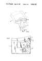
- FIG. 1 is a perspective view of a sensor-initiator of this invention with an associated gas generator and folded bag assembly shown in phantom, and mounted within the vehicle passenger compartment;
- FIG. 2 is a top plan view of the sensor with the cover removed and other parts broken away and removed, showing the sensor armed with dash lines depicting the position of the locking arms when the sensor is safe;
- FIG. 3 is an enlarged fragmentary view of the mass and associated pin extending from a D-shaft prior to movement of the mass incident to a crash;
- FIG. 4 is a similar view showing the mass shifted as a result of a crash and the movement of the associate pin and its D shaft;
- FIG. 5 is an enlarged fragmentary view including the end of the D-shaft and mounting plate supporting the D-shaft;
- FIG. 6 is an enlarged fragmentary view of the firing pin held in a retracted position by the D shaft.
- FIG. 7 is a similar view with the firing pin released when a collision is experienced.
- an air bag safety restraint system 8 incorporating the sensor-initiator of the invention is shown preferably mounted inside a gas generator or inflator 12.
- the inflator 12 is associated with the housing or cover 16 for the folded air bag 18.
- the air bag housing or cover 16 is made of a frangible plastic material and encloses and protects folded air bag 18 to prevent damage to the bag when it is stored and in its uninflated condition.
- the inflator 12 includes housing 32 containing a gas generating material 34 which may be sodium azide. This material is stable over a wide temperature range, but when ignited rapidly decomposes, releasing a large volume of nitrogen gas.
- sensor-initiator 10 which is designed to be mounted outside of the crush zone of a vehicle.
- the sensor-initiator 10 contains a pair of redundant sensors 38 which are adapted to actuate the primers 36 within the housing 40.
- Each sensor 38 includes a sensing mass 41 capable of limited movement within the cylinder 39 contained within the housing 40.
- the movement of sensing mass 41 is damped because air trapped at one end of the cylinder required to flow between the sensing mass 41 and cylinder 39 as the sensing mass moves. Movement of the mass 41 within cylinder 39 is prevented prior to mounting on the vehicle by lock arms 52.
- a pin or projection thereon enters the lock pin hole 52, in the sensor-initiator 10. This pin 48 shifts the conical lock pin 54, permitting springs 55 to rotate the lock arms 52 out of the path of the sensing masses 41, thereby arming the system.
- the locking arms 52 have a common connection and operate under the bias of springs 55 which urge the arms towards one another.
- the larger diameter of conical lock pin 54 keeps locking arms 52 apart and consequently in engagement with the masses 41.
- the pin 54 is urged inwardly the smaller diameter of the conical shape of the lock pin 54 is exposed to the arms which when under the influence of the springs 55 are urged towards one another to thereby free the masses 41.
- Each mass 41 is associated with a pin 56 extending from a D shaft 58.
- the other end of each pin 56 includes the spherical ball 60 in engagement with a biasing spring 62 to assure the interengagement of pin 56 with its associated sensing mass 41.
- Each D shaft 58 is provided with a flat face 64 formed in a generally cylindrically shaped exterior surface.
- a spring biased firing pin 66 is in alignment with the primer 36 and is maintained in a retracted position by the cylindrically shaped exterior of the D shaft 58 and is free to move when aligned with the face 64.
- each sensing mass 41 moves to the right as shown in FIG. 4. However, this motion is resisted by the bias spring 62 acting through the pin 56 and by the air pressure differential between the left and right sides of the mass 41. This pressure is gradually relieved by the flow of air through the clearance between the mass 41 and cylinder 39. If the crash is of sufficient severity, the mass 41 will move sufficiently to the right to cause the D shaft 58 to rotate enough to clear the firing pin 66 and permit the firing pin to move passed face 64 and impact against primer 36. The impact of firing pin 66 ignites the primer 36 which then initiates the ignition of leads 68 which cooperate in initiating the burning of a gas generating material, which in turn, inflates an air bag.
- damping by air has been illustrated here, it is also understood that other forms of damping such as by liquids or magnetically induced electric currents would also work with the proper sensing mass and housing geometry.
- the present invention provides for an all mechanical air bag system in which the sensor is located outside the frontal crush zone having the correct response, and the several aforenoted objects and advantages are most effectively attained.
Landscapes
- Engineering & Computer Science (AREA)
- Mechanical Engineering (AREA)
- Physics & Mathematics (AREA)
- General Physics & Mathematics (AREA)
- Air Bags (AREA)
- Seats For Vehicles (AREA)
Abstract
Description
Claims (11)
Priority Applications (8)
| Application Number | Priority Date | Filing Date | Title |
|---|---|---|---|
| US06/580,336 US4666182A (en) | 1984-02-15 | 1984-02-15 | Non crush zone-all mechanical damped sensor |
| GB08503759A GB2157045B (en) | 1984-02-15 | 1985-02-14 | Non crush zone-all mechanical damped sensor |
| SE8500677A SE8500677L (en) | 1984-02-15 | 1985-02-14 | SENSOR FOR ACTIVATING THE CROSS-SEAT SYSTEM FOR VEHICLES PASSENGERS |
| IT67157/85A IT1183762B (en) | 1984-02-15 | 1985-02-15 | ENTIRELY MECHANICAL SENSOR NOT AVAILABLE IN THE CRUSHING AREA |
| JP60028123A JPS60248456A (en) | 1984-02-15 | 1985-02-15 | Shock sensor |
| FR8502245A FR2559584B1 (en) | 1984-02-15 | 1985-02-15 | FULLY MECHANICAL CUSHIONED DETECTOR FOR NON-CRUSHING AREA |
| CA000474472A CA1238065A (en) | 1984-02-15 | 1985-02-15 | Non crush zone-all mechanical damped sensor |
| DE3505330A DE3505330C2 (en) | 1984-02-15 | 1985-02-15 | Mechanical sensor for triggering a pyrotechnic element of a restraint system for vehicle occupants |
Applications Claiming Priority (1)
| Application Number | Priority Date | Filing Date | Title |
|---|---|---|---|
| US06/580,336 US4666182A (en) | 1984-02-15 | 1984-02-15 | Non crush zone-all mechanical damped sensor |
Publications (1)
| Publication Number | Publication Date |
|---|---|
| US4666182A true US4666182A (en) | 1987-05-19 |
Family
ID=24320671
Family Applications (1)
| Application Number | Title | Priority Date | Filing Date |
|---|---|---|---|
| US06/580,336 Expired - Lifetime US4666182A (en) | 1984-02-15 | 1984-02-15 | Non crush zone-all mechanical damped sensor |
Country Status (8)
| Country | Link |
|---|---|
| US (1) | US4666182A (en) |
| JP (1) | JPS60248456A (en) |
| CA (1) | CA1238065A (en) |
| DE (1) | DE3505330C2 (en) |
| FR (1) | FR2559584B1 (en) |
| GB (1) | GB2157045B (en) |
| IT (1) | IT1183762B (en) |
| SE (1) | SE8500677L (en) |
Cited By (13)
| Publication number | Priority date | Publication date | Assignee | Title |
|---|---|---|---|---|
| US4927172A (en) * | 1988-04-27 | 1990-05-22 | Honda Giken Kogyo Kabushiki Kaisha | Mechanical acceleration sensor |
| US4960292A (en) * | 1988-11-01 | 1990-10-02 | Jaguar Cars Limited | Air bag restraint systems |
| US4991682A (en) * | 1988-01-20 | 1991-02-12 | Gebr. Schmidt Fabrik Fur Feinmechanik | Acceleration sensor |
| US5024157A (en) * | 1989-03-23 | 1991-06-18 | Aisin Seiki Kabushiki Kaisha | Shock detecting device |
| US5032696A (en) * | 1990-07-23 | 1991-07-16 | Buell Industries, Inc. | Crash sensor switch |
| US5178410A (en) * | 1991-06-14 | 1993-01-12 | Breed Automotive Technology, Inc. | Velocity change sensor with lateral shock absorber |
| US5244229A (en) * | 1991-06-14 | 1993-09-14 | Breed Automotive Technology, Inc. | Mechanical crash sensor |
| US5842716A (en) * | 1989-02-23 | 1998-12-01 | Automotive Technologies International, Inc. | Self contained side impact airbag system |
| US5893584A (en) * | 1997-07-08 | 1999-04-13 | Welz Industrie-Produkte Gmbh | Method and apparatus for opening a gas container |
| US6015162A (en) * | 1990-08-23 | 2000-01-18 | Daimlerchrysler Ag | Restraint system for passengers in vehicles |
| DE4219473C2 (en) * | 1991-06-14 | 2002-10-17 | Breed Automotive Tech | Mechanical impact sensor |
| US6685218B1 (en) | 1993-09-16 | 2004-02-03 | Automotive Technologies International, Inc. | Side impact sensors and airbag system |
| USRE39868E1 (en) | 1993-09-16 | 2007-10-09 | Automotive Technologies International, Inc. | Self-contained airbag system |
Families Citing this family (16)
| Publication number | Priority date | Publication date | Assignee | Title |
|---|---|---|---|---|
| JPH0534464Y2 (en) * | 1988-03-11 | 1993-08-31 | ||
| DE4042590C2 (en) * | 1989-03-23 | 1996-05-02 | Aisin Seiki | Impact sensor esp. for triggering impact safety devices |
| JPH084363Y2 (en) * | 1989-08-09 | 1996-02-07 | 株式会社東海理化電機製作所 | Airbag safety device |
| JPH081157Y2 (en) * | 1989-08-09 | 1996-01-17 | 株式会社東海理化電機製作所 | Airbag safety device |
| JPH084364Y2 (en) * | 1989-09-12 | 1996-02-07 | 株式会社東海理化電機製作所 | Airbag safety device |
| JPH03121945U (en) * | 1990-03-27 | 1991-12-12 | ||
| US5431440A (en) * | 1990-08-23 | 1995-07-11 | Deutsche Aerospace Ag | Restraint system for passengers in vehicles with opto-electric trigger means |
| US5193407A (en) * | 1990-12-07 | 1993-03-16 | Aisin Seiki Kabushi Kaisha | Shock detecting device |
| JPH05213152A (en) * | 1991-09-09 | 1993-08-24 | Aisin Seiki Co Ltd | Impact sensing device |
| DE4303405C2 (en) * | 1992-02-07 | 1997-09-11 | Aisin Seiki | Shock detection device |
| US5483846A (en) * | 1992-11-02 | 1996-01-16 | Aisin Seiki Kabushiki Kaisha | Impact sensing apparatus |
| DE19845013A1 (en) | 1998-09-30 | 2000-04-06 | Volkswagen Ag | Safety module with trigger sensor |
| US7628349B2 (en) | 2007-03-06 | 2009-12-08 | Autoliv Asp, Inc. | Inertia actuator for seat belt retractor |
| US7568649B2 (en) | 2007-03-23 | 2009-08-04 | Autoliv Asp, Inc. | Vehicle sensitive seat belt retractor control with suppressed Z-axis sensitivity |
| DE102009052495B8 (en) | 2009-11-11 | 2012-03-22 | Autoliv Development Ab | Self-locking belt retractor |
| US9434347B2 (en) | 2012-12-10 | 2016-09-06 | Autoliv Asp, Inc. | Low noise, debris tolerant retractor inertial sensor |
Citations (4)
| Publication number | Priority date | Publication date | Assignee | Title |
|---|---|---|---|---|
| US3749282A (en) * | 1971-04-02 | 1973-07-31 | Gen Motors Corp | Sensor and trigger mechanism |
| US3968980A (en) * | 1973-02-12 | 1976-07-13 | General Motors Corporation | Occupant restraint system |
| US4161228A (en) * | 1977-01-13 | 1979-07-17 | Forenade Fabriksverken | Vehicle crash detector |
| US4204703A (en) * | 1977-01-31 | 1980-05-27 | Honda Giken Kogyo Kabushiki Kaisha | Device for starting air bag devices |
Family Cites Families (15)
| Publication number | Priority date | Publication date | Assignee | Title |
|---|---|---|---|---|
| GB286562A (en) * | 1927-08-09 | 1928-03-08 | Bofors Ab | Improvements in fuses for armour plate piercing shells or the like projectiles |
| CH148799A (en) * | 1930-08-07 | 1931-08-15 | Schwob Freres & Cie Sa | Self-delayed mechanical percussion fuze for projectiles. |
| NL272706A (en) * | 1960-12-19 | |||
| CH459002A (en) * | 1966-06-21 | 1968-06-30 | Oerlikon Buehrle Holding Ag | Impact fuse for projectiles |
| CH503967A (en) * | 1969-02-20 | 1971-02-28 | Oerlikon Buehrle Ag | bullet |
| US3727575A (en) * | 1971-11-11 | 1973-04-17 | Gen Motors Corp | Bidirectional sensor |
| US3982774A (en) * | 1972-09-26 | 1976-09-28 | Michael Ivashuk | Vehicle crash bag |
| US3859650A (en) * | 1973-11-29 | 1975-01-07 | Gen Motors Corp | Acceleration-responsive sensor with readiness indicator circuit |
| US4116132A (en) * | 1976-12-17 | 1978-09-26 | Technar Incorporated | Inertial sensors |
| US4092926A (en) * | 1976-12-17 | 1978-06-06 | Technar, Incorporated | Mechanical rolamite impact sensor |
| US4167276A (en) * | 1976-12-17 | 1979-09-11 | Allied Chemical Corporation | Self-contained air bag system |
| US4275901A (en) * | 1978-07-21 | 1981-06-30 | Honda Giken Kogyo Kabushiki Kaisha | Inflatable safety bag system for vehicles |
| US4284863A (en) * | 1979-05-09 | 1981-08-18 | Breed Corporation | Velocity change sensor |
| US4329549A (en) * | 1980-04-29 | 1982-05-11 | Breed Corporation | Magnetically biased velocity change sensor |
| JPS577939A (en) * | 1980-06-18 | 1982-01-16 | Toshiba Corp | Manufacture of semiconductor device |
-
1984
- 1984-02-15 US US06/580,336 patent/US4666182A/en not_active Expired - Lifetime
-
1985
- 1985-02-14 GB GB08503759A patent/GB2157045B/en not_active Expired
- 1985-02-14 SE SE8500677A patent/SE8500677L/en not_active Application Discontinuation
- 1985-02-15 DE DE3505330A patent/DE3505330C2/en not_active Expired - Fee Related
- 1985-02-15 CA CA000474472A patent/CA1238065A/en not_active Expired
- 1985-02-15 IT IT67157/85A patent/IT1183762B/en active
- 1985-02-15 FR FR8502245A patent/FR2559584B1/en not_active Expired
- 1985-02-15 JP JP60028123A patent/JPS60248456A/en active Pending
Patent Citations (4)
| Publication number | Priority date | Publication date | Assignee | Title |
|---|---|---|---|---|
| US3749282A (en) * | 1971-04-02 | 1973-07-31 | Gen Motors Corp | Sensor and trigger mechanism |
| US3968980A (en) * | 1973-02-12 | 1976-07-13 | General Motors Corporation | Occupant restraint system |
| US4161228A (en) * | 1977-01-13 | 1979-07-17 | Forenade Fabriksverken | Vehicle crash detector |
| US4204703A (en) * | 1977-01-31 | 1980-05-27 | Honda Giken Kogyo Kabushiki Kaisha | Device for starting air bag devices |
Cited By (23)
| Publication number | Priority date | Publication date | Assignee | Title |
|---|---|---|---|---|
| US4991682A (en) * | 1988-01-20 | 1991-02-12 | Gebr. Schmidt Fabrik Fur Feinmechanik | Acceleration sensor |
| US4927172A (en) * | 1988-04-27 | 1990-05-22 | Honda Giken Kogyo Kabushiki Kaisha | Mechanical acceleration sensor |
| US4960292A (en) * | 1988-11-01 | 1990-10-02 | Jaguar Cars Limited | Air bag restraint systems |
| US5046757A (en) * | 1988-11-01 | 1991-09-10 | Jaguar Cars Limited | Air bag restraint systems |
| US5842716A (en) * | 1989-02-23 | 1998-12-01 | Automotive Technologies International, Inc. | Self contained side impact airbag system |
| US5024157A (en) * | 1989-03-23 | 1991-06-18 | Aisin Seiki Kabushiki Kaisha | Shock detecting device |
| US5032696A (en) * | 1990-07-23 | 1991-07-16 | Buell Industries, Inc. | Crash sensor switch |
| US6015162A (en) * | 1990-08-23 | 2000-01-18 | Daimlerchrysler Ag | Restraint system for passengers in vehicles |
| DE4219473C2 (en) * | 1991-06-14 | 2002-10-17 | Breed Automotive Tech | Mechanical impact sensor |
| US5244229A (en) * | 1991-06-14 | 1993-09-14 | Breed Automotive Technology, Inc. | Mechanical crash sensor |
| US5178410A (en) * | 1991-06-14 | 1993-01-12 | Breed Automotive Technology, Inc. | Velocity change sensor with lateral shock absorber |
| US20050082799A1 (en) * | 1993-09-16 | 2005-04-21 | Breed David S. | Side impact sensor systems |
| US6685218B1 (en) | 1993-09-16 | 2004-02-03 | Automotive Technologies International, Inc. | Side impact sensors and airbag system |
| US20040183287A1 (en) * | 1993-09-16 | 2004-09-23 | Breed David S. | Side impact sensor systems |
| US20050242555A1 (en) * | 1993-09-16 | 2005-11-03 | Breed David S | Side impact sensor systems |
| US7025379B2 (en) | 1993-09-16 | 2006-04-11 | Automotive Technologies International, Inc. | Side impact sensor systems |
| US7052038B2 (en) | 1993-09-16 | 2006-05-30 | Automotive Technologies International Inc. | Side impact sensor systems |
| US7070202B2 (en) | 1993-09-16 | 2006-07-04 | Automotive Technologies International, Inc. | Side impact sensor systems |
| US7097201B2 (en) | 1993-09-16 | 2006-08-29 | Automotive Technologies International, Inc. | Side impact sensor systems |
| US20070040363A1 (en) * | 1993-09-16 | 2007-02-22 | Breed David S | Side Impact Sensor Systems |
| USRE39868E1 (en) | 1993-09-16 | 2007-10-09 | Automotive Technologies International, Inc. | Self-contained airbag system |
| US7334657B2 (en) | 1993-09-16 | 2008-02-26 | Automotive Technologies International, Inc. | Side impact sensor systems |
| US5893584A (en) * | 1997-07-08 | 1999-04-13 | Welz Industrie-Produkte Gmbh | Method and apparatus for opening a gas container |
Also Published As
| Publication number | Publication date |
|---|---|
| SE8500677L (en) | 1985-08-16 |
| GB2157045A (en) | 1985-10-16 |
| SE8500677D0 (en) | 1985-02-14 |
| CA1238065A (en) | 1988-06-14 |
| GB8503759D0 (en) | 1985-03-20 |
| IT8567157A0 (en) | 1985-02-15 |
| DE3505330A1 (en) | 1985-11-21 |
| DE3505330C2 (en) | 1998-09-17 |
| GB2157045B (en) | 1987-06-24 |
| FR2559584A1 (en) | 1985-08-16 |
| JPS60248456A (en) | 1985-12-09 |
| IT1183762B (en) | 1987-10-22 |
| FR2559584B1 (en) | 1988-08-26 |
Similar Documents
| Publication | Publication Date | Title |
|---|---|---|
| US4666182A (en) | Non crush zone-all mechanical damped sensor | |
| US4573706A (en) | Passenger compartment sensor requiring substantial velocity change | |
| US4580810A (en) | Air bag system | |
| US7070202B2 (en) | Side impact sensor systems | |
| US4116132A (en) | Inertial sensors | |
| WO1993001605A1 (en) | Improved spring mass passenger compartment crash sensors | |
| US4819960A (en) | Angled vehicle crash sensor | |
| US4552380A (en) | Self-contained crash bag and initiator | |
| US20090132129A1 (en) | Side Impact Sensor Systems | |
| US5842716A (en) | Self contained side impact airbag system | |
| CA1238066A (en) | Passenger compartment sensor with low bias | |
| USRE39868E1 (en) | Self-contained airbag system | |
| US4715617A (en) | Passenger compartment sensor with low bias | |
| JP2930474B2 (en) | Accident sensor | |
| US6015162A (en) | Restraint system for passengers in vehicles | |
| KR100198391B1 (en) | Air bag impact switch | |
| JPH08268208A (en) | Batch loading type air bag module for side-face collision, mounting method to said car,generating method of said gas, supply of said power and diagnostic method thereof | |
| JPS6218382B2 (en) | ||
| JPH07323811A (en) | Forced operation structure of mechanical ignition type sensor | |
| JPH07117620A (en) | Mechanical ignition sensor | |
| KR20000012185U (en) | Passenger collision safety clearance sheet |
Legal Events
| Date | Code | Title | Description |
|---|---|---|---|
| AS | Assignment |
Owner name: BREED CORPORATION, 170 BEAVER BROOK ROAD, LINCOLN, Free format text: ASSIGNMENT OF ASSIGNORS INTEREST.;ASSIGNOR:BREED, DAVID S.;REEL/FRAME:004231/0016 Effective date: 19840203 |
|
| STCF | Information on status: patent grant |
Free format text: PATENTED CASE |
|
| AS | Assignment |
Owner name: BREED AUTOMOTIVE CORPORATION, ROCKAWAY VALLEY RD., Free format text: ASSIGNMENT OF ASSIGNORS INTEREST.;ASSIGNOR:BREED CORPORATION;REEL/FRAME:004740/0422 Effective date: 19861231 Owner name: BREED AUTOMOTIVE CORPORATION,NEW JERSEY Free format text: ASSIGNMENT OF ASSIGNORS INTEREST;ASSIGNOR:BREED CORPORATION;REEL/FRAME:004740/0422 Effective date: 19861231 |
|
| AS | Assignment |
Owner name: BREED AUTOMOTIVE TECHNOLOGY, INC., P.O. BOX 104, D Free format text: ASSIGNMENT OF ASSIGNORS INTEREST.;ASSIGNOR:BREED AUTOMOTIVE CORPORTION, A CORP. OF DE;REEL/FRAME:004941/0424 Effective date: 19880816 Owner name: BREED AUTOMOTIVE TECHNOLOGY, INC., A CORP. OF DE,D Free format text: ASSIGNMENT OF ASSIGNORS INTEREST;ASSIGNOR:BREED AUTOMOTIVE CORPORTION, A CORP. OF DE;REEL/FRAME:004941/0424 Effective date: 19880816 |
|
| FEPP | Fee payment procedure |
Free format text: PAT HLDR NO LONGER CLAIMS SMALL ENT STAT AS SMALL BUSINESS (ORIGINAL EVENT CODE: LSM2); ENTITY STATUS OF PATENT OWNER: LARGE ENTITY |
|
| AS | Assignment |
Owner name: UNITED JERSEY BANK, 210 MAIN STREET, HACKENSACK, N Free format text: SECURITY INTEREST;ASSIGNOR:BREED AUTOMOTIVE TECHNOLOGY, INC.,;REEL/FRAME:004989/0118 Effective date: 19881215 |
|
| FPAY | Fee payment |
Year of fee payment: 4 |
|
| FEPP | Fee payment procedure |
Free format text: PAYOR NUMBER ASSIGNED (ORIGINAL EVENT CODE: ASPN); ENTITY STATUS OF PATENT OWNER: LARGE ENTITY |
|
| AS | Assignment |
Owner name: CHEMICAL BANK NEW JERSEY, N.A., NEW JERSEY Free format text: SECURITY INTEREST;ASSIGNORS:BREED AUTOMOTIVE MANUFACTURING, INC., A DE CORP.;BREED AUTOMOTIVE CORPORATION, A NJ CORP.;BREED AUTOMOTIVE TECHNOLOGY, INC., A DE CORP.;REEL/FRAME:005957/0152 Effective date: 19911219 Owner name: BREED AUTOMOTIVE TECHNOLOGY, INC. A CORP. OF DEL Free format text: ASSIGNMENT OF ASSIGNORS INTEREST.;ASSIGNOR:UNITED JERSEY BANK A BANKING CORP. OF NEW JERSEY;REEL/FRAME:005951/0296 Effective date: 19911218 |
|
| FPAY | Fee payment |
Year of fee payment: 8 |
|
| FEPP | Fee payment procedure |
Free format text: PAYOR NUMBER ASSIGNED (ORIGINAL EVENT CODE: ASPN); ENTITY STATUS OF PATENT OWNER: LARGE ENTITY Free format text: PAYER NUMBER DE-ASSIGNED (ORIGINAL EVENT CODE: RMPN); ENTITY STATUS OF PATENT OWNER: LARGE ENTITY |
|
| FPAY | Fee payment |
Year of fee payment: 12 |
|
| AS | Assignment |
Owner name: CONGRESS FINANCIAL CORPORATION (FLORIDA), FLORIDA Free format text: SECURITY INTEREST;ASSIGNOR:BREED AUTOMOTIVE TECHNOLOGY, INC.;REEL/FRAME:011442/0646 Effective date: 20001226 |
|
| AS | Assignment |
Owner name: BREED AUTOMOTIVE TECHNOLOGY, INC., MICHIGAN Free format text: RELEASE OF SECURITY INTEREST IN TRADEMARKS;ASSIGNOR:CONGRESS FINANCIAL CORPORATION;REEL/FRAME:014313/0243 Effective date: 20030725 |
|
| AS | Assignment |
Owner name: CITICORP USA, INC., AS TERM C LOAN COLLATERAL AGEN Free format text: SECURITY AGREEMENT;ASSIGNOR:BREED AUTOMOTIVE TECHNOLOGY, INC.;REEL/FRAME:014428/0283 Effective date: 20030425 |