US4668460A - Method of molding and coating a substrate in a mold. - Google Patents
Method of molding and coating a substrate in a mold. Download PDFInfo
- Publication number
- US4668460A US4668460A US06/849,222 US84922286A US4668460A US 4668460 A US4668460 A US 4668460A US 84922286 A US84922286 A US 84922286A US 4668460 A US4668460 A US 4668460A
- Authority
- US
- United States
- Prior art keywords
- coating
- substrate
- mold cavity
- pressure
- dies
- Prior art date
- Legal status (The legal status is an assumption and is not a legal conclusion. Google has not performed a legal analysis and makes no representation as to the accuracy of the status listed.)
- Expired - Lifetime
Links
Images


Classifications
-
- B—PERFORMING OPERATIONS; TRANSPORTING
- B29—WORKING OF PLASTICS; WORKING OF SUBSTANCES IN A PLASTIC STATE IN GENERAL
- B29C—SHAPING OR JOINING OF PLASTICS; SHAPING OF MATERIAL IN A PLASTIC STATE, NOT OTHERWISE PROVIDED FOR; AFTER-TREATMENT OF THE SHAPED PRODUCTS, e.g. REPAIRING
- B29C43/00—Compression moulding, i.e. applying external pressure to flow the moulding material; Apparatus therefor
- B29C43/02—Compression moulding, i.e. applying external pressure to flow the moulding material; Apparatus therefor of articles of definite length, i.e. discrete articles
- B29C43/14—Compression moulding, i.e. applying external pressure to flow the moulding material; Apparatus therefor of articles of definite length, i.e. discrete articles in several steps
- B29C43/146—Compression moulding, i.e. applying external pressure to flow the moulding material; Apparatus therefor of articles of definite length, i.e. discrete articles in several steps for making multilayered articles
-
- B—PERFORMING OPERATIONS; TRANSPORTING
- B29—WORKING OF PLASTICS; WORKING OF SUBSTANCES IN A PLASTIC STATE IN GENERAL
- B29C—SHAPING OR JOINING OF PLASTICS; SHAPING OF MATERIAL IN A PLASTIC STATE, NOT OTHERWISE PROVIDED FOR; AFTER-TREATMENT OF THE SHAPED PRODUCTS, e.g. REPAIRING
- B29C37/00—Component parts, details, accessories or auxiliary operations, not covered by group B29C33/00 or B29C35/00
- B29C37/0025—Applying surface layers, e.g. coatings, decorative layers, printed layers, to articles during shaping, e.g. in-mould printing
- B29C37/0028—In-mould coating, e.g. by introducing the coating material into the mould after forming the article
-
- B—PERFORMING OPERATIONS; TRANSPORTING
- B29—WORKING OF PLASTICS; WORKING OF SUBSTANCES IN A PLASTIC STATE IN GENERAL
- B29C—SHAPING OR JOINING OF PLASTICS; SHAPING OF MATERIAL IN A PLASTIC STATE, NOT OTHERWISE PROVIDED FOR; AFTER-TREATMENT OF THE SHAPED PRODUCTS, e.g. REPAIRING
- B29C70/00—Shaping composites, i.e. plastics material comprising reinforcements, fillers or preformed parts, e.g. inserts
- B29C70/04—Shaping composites, i.e. plastics material comprising reinforcements, fillers or preformed parts, e.g. inserts comprising reinforcements only, e.g. self-reinforcing plastics
- B29C70/28—Shaping operations therefor
- B29C70/40—Shaping or impregnating by compression not applied
- B29C70/42—Shaping or impregnating by compression not applied for producing articles of definite length, i.e. discrete articles
- B29C70/46—Shaping or impregnating by compression not applied for producing articles of definite length, i.e. discrete articles using matched moulds, e.g. for deforming sheet moulding compounds [SMC] or prepregs
Definitions
- thermosetting plastics has become widespread. Particularly in the automotive industry where weight is a significant factor, molding of plastic parts for interior parts and exterior panels has become common.
- exterior class "A" panels are formed of a composite of specialty polyester resins, thickeners, thermoplastic copolymers, mineral fillers, fiber reinforcements, catalysts, and release agents. These materials are commonly combined (with different variations) in a sheet form and are known as "SMC.”
- SMC Standard Coating Process and Specifications
- the dies are forced closed by a press ram under high forces that cause pressures on the substrate up to about 1500 psi.
- the initial pressure must be high enough to form the substrate into the shape of the mold cavity.
- different pressures are required. This molding process is commonly carried out at 300° F. but different temperatures, for example, 100° to about 400° F., may be used.
- the molded products resulting from Compression Molding can have surface defects, such as surface pits, porosity, sink marks and shrink cracks.
- surface defects such as surface pits, porosity, sink marks and shrink cracks.
- a technique of in-mold coating has been developed. The process for molding and in-mold coating presently includes the following sequence:
- level control cylinders try to maintain the dies in parallel condition while closing
- the level control cylinder readjusts to try to maintain parallelism while reclosing to allow the coating to spread evenly across the part surface
- the opening and closing of the mold, the depressurizing and repressurizing, and their accompanying level adjustment are major time delays in the in-mold coating process.
- a typical example of this process is illustrated in FIGS. 4 and 5 of U.S. Pat. No. 4,076,778 to Edwin D. Ditto, which is incorporated herein by reference. It is estimated that this opening and closing of the molds take up 5 to 20 percent of the total molding and coating process time. When the millions and millions of parts that are molded yearly are considered, the inefficiency and cost of this opening-closing routine are staggering.
- the reopening and reclosing of the mold cause other problems as well. Opening of the dies causes the flashing around the shear edges to enter the mold cavity. Disturbance of the shear edge may cause an incomplete seal after reclosing. Moreover, the open-close coating method precludes the possibility of using secondary cores or slides in the mold. The slide usually comes in at an angle to one of the dies, and thus cannot be used if the die moves relative to the substrate. Another major limitation of in-mold coating as presently practiced is that it is not readily applicable to injection or reaction injection molding processes. These types of molding processes do not use dies that normally have shear edge construction.
- This invention includes the process of molding parts and coating them in the mold. It includes forming a substrate in any mold having at least two separable parts and at least partially curing it to the degree that it has a surface receptive to a coating. The coating is injected into the mold at a high pressure without reopening or reclosing the mold. The coated part is subsequently cured and removed.
- the prior art method of coating in the mold as described in Ditto required that the substrate be molded until it had hardened sufficiently to retain its shape during opening of the mold and injection of the coating.
- the substrate need only be cured sufficiently to provide a surface which is receptive to the coating. This frequently allows injection of the coating at an earlier time in the molding cycle and thereby shortens the time required for the entire molding cycle.
- the high pressure injection also appears to coat more uniformly than low pressure injection.
- the use of mechanisms to ensure parallelism of the dies does not appear to be necessary for this coating process, although it may still be necessary to ensure even flow of the substrate in the die cavity.
- the precision mold opening devices commonly used in the prior art such as precision push-back systems for separating the dies prior to injection of the coating, are normally not necessary in the process of this invention.
- FIG. 1 is a schematic representation of the compression mold and injection means
- FIGS. 2-6 illustrate a process of compression molding utilizing in-mold coating.
- FIG. 1 The general system of the process of this invention is illustrated in FIG. 1. It includes a mold 10 made up of dies 12,14 which are generally nested in the sense that they form a mold cavity 16 therebetween and have complementary surfaces 17 and 18.
- the concave surface 17 forms the bottom of the die of cavity 12.
- the convex surface 18 forms the upper surface of the lower die 14, also frequently called the "core.”
- the shear edges 19 and 20 on the die 14 and 21 and 22 on the die 12 are dimensioned to closely interfit with a very small dimensional difference. It is important that the shear edges in compression molding are very accurately dimensioned, since the substrate used in the molds goes into the shear edges and, when it begins to cure, acts as a seal.
- Horizontal surfaces 23,24 on the lower die 14 interfit with complementary surfaces 26 and 28 on the upper die 12. At times, spacers or stops are used between the dies to ensure parallelism.
- the lower die 14 sits on a press bed 30 and the upper die 12 is motivated downwardly by a press ram 31. Cylinders or other means for separating the dies are also built into such machines, but are not shown.
- An injection means generally shown as 32, includes an injector 34, pump means 36, and appropriate conduit system 38.
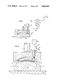
- the injector 34 as particularly shown in FIGS. 2 through 6 includes an actuator 48 of any known type, such as hydraulic or electric.
- An injector housing 50 surrounds a pin 52 which passes therethrough and is operatively connected to the actuator 48.
- An example of such an injector is Model No. MRF 600-625-250, manufactured by The Morrell Co., Inc.
- a chamber 70 in the housing 50 connects a bore 68 in the die 12 with a conduit 72 leading to the pump means 36. Conduit 72 is part of the conduit system 38.
- the chamber 70 is generally complementary with the shape of the pin 52, and has appropriate seals between it and the pin 52 to ensure fluidtight operation.
- Conduit 38 would normally include the fittings, hoses, tubes, pipes, etc. which are necessary in this type of process.
- the connectors, fittings, and conduits should have an operating pressure substantially in excess of the pressures generated by the pump of the coating. In this particular embodiment, it may mean operating pressures of 5000 or 6000 psi, or even higher.
- the pump means 36 includes a first high pressure pump 74. Any type of high pressure pump for coating means will be applicable, and a typical commercially available one would be the Model No. 206-445, manufactured by Graco Co.
- the output of the pump 74 goes through a conduit 76 and to a second high pressure pump, or metering pump, which steps up the pressure of the coating.
- the coating may be a one-component system as illustrated in FIG. 1, or a two or more component system. This invention is not limited to any particular type of coating or coating system.
- the second high pressure metering pump may be of any commercially available type, such as Model No. 851002000, manufactured by The Morrell Company, Inc.
- the coatings which are useful in the in-mold coating process of this invention include any coating which could be polymerized and/or cross-linked within the mold. These coatings typically are cured or polymerized by free radical and/or condensation polymerization methods and can include both single-component and two-component coatings, as are well-known in the art. Representative coatings include acrylic and acrylic ester polymers, saturated and unsaturated polyesters, epoxy esters, active hydrogen containing resins cross-linkable by blocked or free isocyanates and others. If a two-component resin system is used, the components are mixed, typically by a static mixer such as that made by Kenics Corporation, immediately prior to injection into the mold.
- cure time required for the coatings should be slow enough to allow the coatings to flow over the molded part in the mold prior to excessive gellation, but short enough to allow substantial curing within the molding cycle. Typically, cure times will run from about 15 to about 100 seconds at mold temperatures of about 300° F.
- the in-mold coatings may also contain pigments, conductive materials such as carbon black, mold release agents such as dialkyl phosphates, initiators, catalysts, accelerators, flow agents, thickeners and other additives.
- pigments such as carbon black
- mold release agents such as dialkyl phosphates, initiators, catalysts, accelerators, flow agents, thickeners and other additives.
- Representative one-component in-mold coatings typical of those useful in this invention include those taught in U.S. Pat. Nos. 4,235,833 and 4,239,808 (free radical polymerizable vinyl ester resin/polyvinyl acetate/styrene); U.S. Pat. Nos. 4,293,659 and 4,366,109 (polymerizable blocked isocyanate/ethylenically unsaturated polymer/ethylenically unsaturated monomer); U.S. Pat. No. 4,414,173 (polymerizable epoxy-based oligomer/copolymerizable monomer; copolymerizable monoethylenically unsaturated compound/ polyvinyl acetate); U.S.
- Representative two-component coating systems include the coatings taught in U.S. Pat. No. 4,081,578 (polyisocyanate/active hydrogen containing resin); and U.S. Pat. No. 4,189,517 (diisocyanate/unsaturated polyester/saturated polyester diol flexibilizer/cross-linking polyol).
- the teaching of coating materials useful in in-mold coating in all of these patents is hereby incorporated by reference.
- the coating is added to the mold in amounts sufficient to provide coverage of the plastic part to the desired film thickness.
- the coating will provide a final cure film thickness of at least 0.1 mils and could range up to a thickness of about 20 mils.
- the film thicknesses range from about 1.0 to about 10 mils of cured coating.
- FIGS. 2 through 6 One process of this invention of molding and in-mold coating is illustrated in FIGS. 2 through 6. Initially the SMC charge 90 is placed on the lower die 14 when the dies are separated or the mold is open. In such position, the pin 52 blocks the bore 68 so that the coating cannot flow into the mold cavity 16. Although this process is described in terms of the sheet molding material, it should be understood that any type of material or form of material, such as bulk molding compound, or other plastics, may be utilized.
- thermosetting plastic substrate Any thermosetting or thermoplastic plastic substrate could be used in the practice of this invention.
- thermosetting plastics include the compression and injection molded plastics, such as unsaturated polyesters as in SMC, epoxies, phenolics, silicones, polyurethanes, etc.
- useful thermoplastic materials include polyethylene, ABS, PVC, polystyrene, polypropylene, acrylics, etc.
- mold cavity pressure means the force exerted by the ram press divided by the top surface area of the formed substrate 96. In compression molding, this pressure would typically be in the area of 500 psi to 2000 psi. At this point, the pin 52 blocks the coating from the injection system 36.
- a sequentially timed actuator 48 or other type of actuator retracts the pin 52 in FIG. 4, allowing the coating at a substantially higher pressure than the mold cavity pressure to flow through the conduit 72, chamber 70, and bore 68, into the mold cavity 16.
- Substantially higher pressure means a pressure sufficient to overcome the positive mold cavity pressure to the point where the coating spreads over the surface of the substrate.
- the pressure of the injected coating will be at least two times, and more often at least four times, the mold cavity pressure immediately prior to injection. Because of the very high pressure of the coating material, it coats the substrate 90 evenly without retraction of the die 12. It is only necessary in the timing cycle that the substrate 90 be cured to the point where it has formed a skin and is thus receptive to a coating.
- the substrate polymers cross-link and shrink. As the substrate shrinks, the dies move toward each other to fill up the space. When the coating is subsequently injected at high pressures into the mold cavity 16, it acts to further compress the substrate 90. It is possible that the addition of the coating at high pressure may also raise the die 12 very slightly in spite of maintaining a ram pressure. Any movement of the dies, however, is ancillary to the injection of the coating and is not intentionally done and does not precede the step of the injection. It is also important to note that the pressure is maintained in the mold cavity 16 and that the mold remains closed, that is the dies 11 and 12 remain in position and continue to define substantially the same mold cavity 16 prior to and during the injection of the coating.
- the coating By maintaining the dies in a fully closed position and maintaining the mold cavity, and therefore the substrate, under positive mold cavity pressure, e.g. greater than atmospheric pressure and typically at least 100 psi and frequently at least 500 psi, the coating, when injected at a substantially greater pressure than the positive mold cavity pressure, is forced over the surface of the substrate thereby compressing the substrate slightly and causing the coating to cover the surface without the requirement of depressurizing and/or reopening the mold prior to or contemporaneously with the injection of the coating followed by repressurizing and reclosing of the dies.
- positive mold cavity pressure e.g. greater than atmospheric pressure and typically at least 100 psi and frequently at least 500 psi
- the actual mold cavity pressure prior to the injection may be the original molding pressure utilized to force the substrate into the proper form. Alternately, the pressure in the mold cavity immediately preceding the coating injection may be lower than the molding pressure. It is common in the molding industry to sometimes utilize a two-pressure molding technique. In this technique, the original high pressure, eg. 500 to 2000 psi, is utilized to form the substrate and a subsequent lower pressure typically of about one-fourth to three-fourths of the forming pressure, e.g. 100 to 600 psi is used during the partial curing of the substrate. However, low pressure systems sometimes use molding pressures as low as 100-150 psi. Representative low pressure systems would include reaction injection molding processes.
- the amount of coating injected into the mold can be controlled in any one of several known manners. For example, as shown in the above-noted Ditto patent, a predetermined amount of coating can be captured in a chamber and then released. Alternately, a timing mechanism can be used to meter the coating at a predetermined rate, and therefore a known volume, into the mold cavity.
- the pin 52 is moved downwardly, as shown in FIG. 5, by the actuator 48 to again block the opening to the bore 68.
- the coated, formed substrate is then maintained in the mold cavity for a period of time, depending on the size and shape of the article, until both the coating and the substrate are cured.
- the dies are separated, usually by pistons (not shown), and the finished product is removed.
Abstract
Description
Claims (28)
Priority Applications (1)
| Application Number | Priority Date | Filing Date | Title |
|---|---|---|---|
| US06/849,222 US4668460A (en) | 1985-04-02 | 1986-04-07 | Method of molding and coating a substrate in a mold. |
Applications Claiming Priority (2)
| Application Number | Priority Date | Filing Date | Title |
|---|---|---|---|
| US71891385A | 1985-04-02 | 1985-04-02 | |
| US06/849,222 US4668460A (en) | 1985-04-02 | 1986-04-07 | Method of molding and coating a substrate in a mold. |
Related Parent Applications (1)
| Application Number | Title | Priority Date | Filing Date |
|---|---|---|---|
| US71891385A Continuation-In-Part | 1985-04-02 | 1985-04-02 |
Publications (1)
| Publication Number | Publication Date |
|---|---|
| US4668460A true US4668460A (en) | 1987-05-26 |
Family
ID=27110000
Family Applications (1)
| Application Number | Title | Priority Date | Filing Date |
|---|---|---|---|
| US06/849,222 Expired - Lifetime US4668460A (en) | 1985-04-02 | 1986-04-07 | Method of molding and coating a substrate in a mold. |
Country Status (1)
| Country | Link |
|---|---|
| US (1) | US4668460A (en) |
Cited By (67)
| Publication number | Priority date | Publication date | Assignee | Title |
|---|---|---|---|---|
| US4823434A (en) * | 1986-10-17 | 1989-04-25 | Aisin Seiki Kabushiki Kaisha | Outer door handle |
| US5009821A (en) * | 1989-02-23 | 1991-04-23 | Libbey-Owens-Ford Co. | Molding method for eliminating fiber readout |
| US5174933A (en) * | 1989-12-07 | 1992-12-29 | Mazda Motor Corporation | Method of and apparatus for producing a product with a coating layer |
| US5277567A (en) * | 1990-03-23 | 1994-01-11 | Krauss Maffei Ag | Apparatus for mixing reactive synthetic-resin components |
| US5387750A (en) * | 1993-08-27 | 1995-02-07 | The Sherwin-Williams Company | Two-component urethane in-mold coating composition |
| US5474134A (en) * | 1991-01-16 | 1995-12-12 | Krauss-Maffei Ag | System for making a molded laminate |
| US5676901A (en) * | 1992-06-19 | 1997-10-14 | Matsushita Electric Works, Ltd. | Process for resin-coating of resin moldings, resin-coating apparatus for use in the process |
| US5736090A (en) * | 1995-03-23 | 1998-04-07 | Dai Nippon Tokyo Co., Ltd. | Method of in-mold coating |
| US5849168A (en) * | 1996-06-14 | 1998-12-15 | Acushnet Company | Method of in-mold coating golf balls |
| US5885662A (en) * | 1997-01-31 | 1999-03-23 | Atoma International, Inc. | Decorative automotive interior trim articles with integral light stable polyurethane elastomer covering and process for making the same |
| US5902534A (en) * | 1994-09-21 | 1999-05-11 | Mitsubishi Engineering-Plastics Corp. | Method of injection-molding thermoplastic resins |
| US6013210A (en) * | 1997-04-18 | 2000-01-11 | Magna Interior Systems Inc. | Process for making decorative automotive interior trim articles with cast integral light stable covering |
| US6180043B1 (en) * | 1998-01-27 | 2001-01-30 | Dai Nippon Toryo Co., Ltd. | Method of in-mold coating |
| US6210614B1 (en) | 1997-06-16 | 2001-04-03 | Atoma International Inc. | Process of making decorative automotive interior trim articles with cast integral light-stable covering containing invisible tear seam |
| US6328920B1 (en) * | 1996-11-27 | 2001-12-11 | Honda Engineering North America, Inc. | Molding process for forming complex shapes |
| WO2002004187A2 (en) * | 2000-07-12 | 2002-01-17 | Omnova Solutions Inc. | Method for in-mold coating a polyolefin article |
| US6413461B1 (en) * | 1998-05-08 | 2002-07-02 | Sumitomo Chemical Company, Limited | Process for producing multilayer molded article |
| US6544449B1 (en) | 1998-05-22 | 2003-04-08 | Magna Interior Systems Inc. | Process for making decorative automotive interior trim articles with integral in-mold coated polyurethane aromatic elastomer covering |
| US20030077425A1 (en) * | 2001-10-22 | 2003-04-24 | Omnova Solutions Inc. | In-mold coating barrier for a substrate injection orifice |
| US20030077426A1 (en) * | 2001-10-22 | 2003-04-24 | Omnova Solutions Inc. | In-mold coating injection inlet flow control |
| US20030099809A1 (en) * | 2001-10-22 | 2003-05-29 | Omnova Solutions Inc. | Removable defined flange for in-mold coating containment |
| US20030104168A1 (en) * | 2001-12-03 | 2003-06-05 | Kyle Shane | In-mold-coated automotive interior and other products, and methods for manufacturing same |
| US20030224172A1 (en) * | 2002-05-31 | 2003-12-04 | Omnova Solutions Inc. | In-mold primer coating for thermoplastic substrates |
| US20030224189A1 (en) * | 2002-05-31 | 2003-12-04 | Omnova Solutions Inc. | In-mold appearance coatings for nylon and nylon based thermoplastic substrates |
| US6676877B2 (en) | 2002-04-03 | 2004-01-13 | Omnova Solutions Inc. | Mold runner for prevention of in-mold coating flow |
| US20040071980A1 (en) * | 2000-07-12 | 2004-04-15 | Mcbain Douglas S. | Method for in-mold coating a polyolefin article |
| US6745470B2 (en) * | 2000-05-15 | 2004-06-08 | Meritor Heavy Vehicle Technology, Llc | Vehicle with large planar composite panels |
| US20040121034A1 (en) * | 2002-12-10 | 2004-06-24 | Mcbain Douglas S. | Integral injection molding and in-mold coating apparatus |
| US6756003B2 (en) * | 2002-03-04 | 2004-06-29 | Visteon Global Technologies, Inc. | Method of attaching thermoplastic attachments to a substrate |
| US6793861B2 (en) | 2000-07-12 | 2004-09-21 | Omnova Solutions Inc. | Optimization of in-mold coating injection molded thermoplastic substrates |
| US20040182820A1 (en) * | 2003-03-20 | 2004-09-23 | Shigehisa Motowaki | Nanoprint equipment and method of making fine structure |
| US6822058B1 (en) | 2000-07-14 | 2004-11-23 | The Sherwin-Williams Company | Low-temperature in-mold coating composition |
| US20050003204A1 (en) * | 2004-09-28 | 2005-01-06 | Thomas Frankel | Mutiple layered membrane with fluorine containing polymer layer |
| US6890469B2 (en) | 2001-10-22 | 2005-05-10 | Omnova Solutions Inc. | Selectively controlling in-mold coating flow |
| US20050116384A1 (en) * | 2003-12-02 | 2005-06-02 | Hiromi Hyuga | Method for manufacturing in-mold coating product |
| US20050274821A1 (en) * | 2004-06-11 | 2005-12-15 | Lear Corporation | Heated spray applicator |
| US20060009570A1 (en) * | 2004-06-10 | 2006-01-12 | Zychowski Frank D | Free radical curable conductive primer |
| US20060057335A1 (en) * | 2004-09-14 | 2006-03-16 | Chen-Shih Wang | Molded fiber panel having reduced surface fiber readout and method of molding thereof |
| US20060058910A1 (en) * | 2002-12-12 | 2006-03-16 | Mcbain Douglas | Method of designing and producing a mold |
| US20060070347A1 (en) * | 2004-09-23 | 2006-04-06 | Manish Gupta | Impact resistant door facing, method of forming impact resistant door facing, and door formed therewith |
| US20060076712A1 (en) * | 1999-07-27 | 2006-04-13 | Dai Nippon Toryo Co., Ltd | Method of forming a coating layer on the surface of a molded product within a mold |
| US20060113693A1 (en) * | 2002-11-22 | 2006-06-01 | Mcbain Douglas | Method for modifying existing mold systems to utilize an in-mold apparatus |
| EP1666225A1 (en) | 2004-12-06 | 2006-06-07 | Bayer MaterialScience LLC | Method of preparing a coated molded article |
| US20060151911A1 (en) * | 2004-12-24 | 2006-07-13 | Olaf Zollner | Process and mold for molding and coating a substrate |
| US20060226574A1 (en) * | 2003-08-25 | 2006-10-12 | Bozio Ronald A | Trim panel |
| US20060267233A1 (en) * | 2002-09-04 | 2006-11-30 | Kent Sherwood | Enhanced reinforced foam core construction |
| US20070063451A1 (en) * | 2005-09-20 | 2007-03-22 | Bayer Materialscience Llc | Gasket |
| US20070230196A1 (en) * | 2006-03-30 | 2007-10-04 | Chen-Shih Wang | Composite products and methods of making the same |
| US20080008868A1 (en) * | 2006-07-05 | 2008-01-10 | General Motors Corporation | Molding cosmetic composite panels with visible fibers from ultraviolet light resistant epoxy compositions |
| US20080088058A1 (en) * | 2006-05-18 | 2008-04-17 | General Motors Corporation | Method for molding cosmetic composite panels with visible carbon fiber weaves |
| US20080265459A1 (en) * | 2007-04-27 | 2008-10-30 | Gasworth Steven M | Abrasion resistant plastic glazing with in-mold coating |
| DE102007021679A1 (en) | 2007-05-09 | 2008-11-13 | Kraussmaffei Technologies Gmbh | Method for expansion of flow with a movable cavity core, comprises latching the cavity core and producing a cavity with a first volume, injecting a first material into the cavity, and partially cooling and hardening the first material |
| US20080286537A1 (en) * | 2007-05-09 | 2008-11-20 | Christophe Lefaux | Pre-dry treatment of ink in decorative plastic glazing |
| US20080317893A1 (en) * | 2006-03-03 | 2008-12-25 | Kraussmaffei Technologies Gmbh | Integrated system for producing composites |
| US20100201028A1 (en) * | 2009-02-12 | 2010-08-12 | Yeong-Eun Yoo | Fabrication method of products with closed channels by injection molding |
| WO2013053612A1 (en) * | 2011-10-11 | 2013-04-18 | Kraussmaffei Technologies Gmbh | Method for coating a molded part |
| US20130234353A1 (en) * | 2010-04-15 | 2013-09-12 | Coexpair | Method and apparatus for moulding parts made from composite materials |
| US20140084636A1 (en) * | 2011-03-24 | 2014-03-27 | Webasto Ag | Plastic component of a roof opening system |
| US20140184026A1 (en) * | 2012-12-31 | 2014-07-03 | Volcano Corporation | Wirebonding Fixture and Casting Mold |
| CN103991150A (en) * | 2014-06-10 | 2014-08-20 | 德清三盛氟塑科技有限公司 | High-temperature valve seat bush forming mould assembly |
| US20140242373A1 (en) * | 2012-04-17 | 2014-08-28 | Ford Global Technologies, Llc | Composite Part Assembly |
| US9139242B2 (en) | 2007-05-01 | 2015-09-22 | Exatec Llc | Encapsulated plastic panel and method of making the same |
| US20150282358A1 (en) * | 2014-03-28 | 2015-10-01 | Mark E. Sprenger | Composite chassis with cosmetic finish |
| US20150298373A1 (en) * | 2012-11-23 | 2015-10-22 | Webasto SE | Method for producing a flat motor vehicle body member and motor vehicle body member |
| US20170157804A1 (en) * | 2014-01-17 | 2017-06-08 | Toray Industries, Inc. | Coated fiber-reinforced resin molded article and manufacturing method of the same |
| US10814803B2 (en) | 2015-06-03 | 2020-10-27 | Weidplas Gmbh | Component |
| US11453182B2 (en) * | 2019-12-05 | 2022-09-27 | GM Global Technology Operations LLC | Methods for forming class-A components with moldable carbon fiber |
Citations (46)
| Publication number | Priority date | Publication date | Assignee | Title |
|---|---|---|---|---|
| US721462A (en) * | 1902-05-26 | 1903-02-24 | Francis H Richards | Manufacture of playing-balls. |
| US2131319A (en) * | 1933-01-03 | 1938-09-27 | Crown Cork & Seal Co | Method and apparatus for making composite caps |
| US2890491A (en) * | 1954-08-26 | 1959-06-16 | Tube Turns Plastics Inc | Injection molding process for unplasticized polyvinyl chloride |
| US3026573A (en) * | 1956-12-26 | 1962-03-27 | Modern Shoe Making Machine Cor | Method of stiffening a shoe upper |
| US3028284A (en) * | 1953-11-24 | 1962-04-03 | John F Reeves | Molding method for plastic bodies |
| US3077658A (en) * | 1960-04-11 | 1963-02-19 | Gen Dynamics Corp | Method of manufacturing molded module assemblies |
| US3087201A (en) * | 1960-03-02 | 1963-04-30 | Us Rubber Co | Method of injection molding fabricreinforced articles |
| US3096146A (en) * | 1961-02-16 | 1963-07-02 | Phillips Petroleum Co | Decoratively colored thermoplastic article and process for making the same |
| US3184527A (en) * | 1962-11-05 | 1965-05-18 | Us Rubber Co | Squeeze-coating process |
| US3192299A (en) * | 1961-06-28 | 1965-06-29 | Borg Warner | Injection molding machine and process for plasticizing plastic material |
| US3319301A (en) * | 1964-10-20 | 1967-05-16 | Herbert P Ludwig | Injection molding shoe bottoms |
| US3507730A (en) * | 1964-02-28 | 1970-04-21 | Owens Corning Fiberglass Corp | Method of producing a composite wall panel |
| US3516123A (en) * | 1966-10-03 | 1970-06-23 | Theo O Lang | Injection molding machine |
| US3611505A (en) * | 1968-12-27 | 1971-10-12 | Harry Dudley Wright | Plastic moulding machines |
| US3670066A (en) * | 1969-11-10 | 1972-06-13 | Emery I Valyi | Method of compression molding a thermoplastic article with walls of variable thickness |
| US3694541A (en) * | 1970-07-06 | 1972-09-26 | Owens Corning Fiberglass Corp | Method for forming a molded article |
| US3709973A (en) * | 1966-12-23 | 1973-01-09 | Bata Shoe Co | Manufacture of footwear and/or components thereof by injection molding of synthetic resinous material or other molding materials |
| US3709644A (en) * | 1970-11-25 | 1973-01-09 | J Farrell | Time saver plastic draw-back valve assembly |
| US3723037A (en) * | 1970-11-04 | 1973-03-27 | Plastics Inc | Apparatus for injection molding articles from aminoplastic material |
| US3801244A (en) * | 1972-02-08 | 1974-04-02 | H Eisenberg | Apparatus for making a foamed article having a plastic skin bonded thereto |
| US3819313A (en) * | 1970-04-02 | 1974-06-25 | Allied Chem | Apparatus for molding articles |
| US3847525A (en) * | 1970-06-26 | 1974-11-12 | Krauss Maffei Ag | Apparatus for the injection molding of synthetic-resin articles |
| DE2444267A1 (en) * | 1973-09-24 | 1975-04-03 | Asea Ab | PROCESS FOR MANUFACTURING AN ARTICLE FROM PLASTIC, ON WHICH AT LEAST ONE SURFACE SHAPED IN AN INJECTION MOLDING TOOL IS COVERED WITH METAL |
| US4012386A (en) * | 1973-10-11 | 1977-03-15 | Stokes-Trenton, Inc. | Process for making plastic bowling pins |
| US4014966A (en) * | 1972-09-06 | 1977-03-29 | Robert Hanning | Method for injection molding a composite foamed body having a foamed core and a continuous surface layer |
| US4076788A (en) * | 1976-12-02 | 1978-02-28 | General Motors Corporation | Mold coating of freshly molded articles |
| US4076780A (en) * | 1977-01-27 | 1978-02-28 | General Motors Corporation | Programmable velocity and force control method for compression molding |
| US4081578A (en) * | 1974-06-27 | 1978-03-28 | The General Tire & Rubber Company | In-mold coating composition and method of applying same |
| US4082486A (en) * | 1976-12-02 | 1978-04-04 | General Motors Corporation | Apparatus for in-the-mold coating of molded articles |
| US4189517A (en) * | 1978-11-08 | 1980-02-19 | The General Tire & Rubber Company | Low-shrink in-mold coating |
| US4235833A (en) * | 1977-07-11 | 1980-11-25 | The General Tire & Rubber Company | In-the-mold coating apparatus and method |
| US4239808A (en) * | 1979-06-13 | 1980-12-16 | The General Tire & Rubber Company | In-mold coating of sheet molding compound moldings |
| US4239796A (en) * | 1979-06-21 | 1980-12-16 | The General Tire & Rubber Company | In-mold coating of structural foams and resultant product |
| US4245006A (en) * | 1979-05-18 | 1981-01-13 | The General Tire & Rubber Company | Low-pressure low-temperature in-mold coating method |
| US4282285A (en) * | 1979-10-24 | 1981-08-04 | International Telephone & Telegraph Corporation | Process for preparing polyurethane molded part |
| US4293659A (en) * | 1980-05-01 | 1981-10-06 | Freeman Chemical Corporation | Composition for coating molded articles |
| US4350739A (en) * | 1979-07-30 | 1982-09-21 | International Telephone And Telegraph Corporation | Molded plastic part |
| US4351789A (en) * | 1981-07-27 | 1982-09-28 | The B. F. Goodrich Company | Mold and process for molding |
| US4356230A (en) * | 1980-07-10 | 1982-10-26 | International Telephone And Telegraph Corporation | Molded plastic product having a plastic substrate containing a filler and an in-mold plastic coating firmly bonded thereon and a process for its manufacture |
| US4366109A (en) * | 1980-05-01 | 1982-12-28 | Freeman Chemical Corporation | Method for making coated molded articles |
| US4367192A (en) * | 1977-07-11 | 1983-01-04 | The General Tire & Rubber Company | In-mold coating of sheet molding compound moldings |
| US4369157A (en) * | 1977-04-11 | 1983-01-18 | Dri-Print Foils, Inc. | Method of automatically decorating articles as they are in-mold formed automatically |
| US4414173A (en) * | 1981-11-02 | 1983-11-08 | The General Tire & Rubber Company | In-mold coating |
| US4422996A (en) * | 1980-05-01 | 1983-12-27 | Freeman Chemical Corporation | Method for making coated molded articles |
| US4438062A (en) * | 1983-04-14 | 1984-03-20 | The General Tire & Rubber Company | In-mold coating method |
| US4477405A (en) * | 1981-12-31 | 1984-10-16 | Ppg Industries, Inc. | Method of in-mold coating |
-
1986
- 1986-04-07 US US06/849,222 patent/US4668460A/en not_active Expired - Lifetime
Patent Citations (46)
| Publication number | Priority date | Publication date | Assignee | Title |
|---|---|---|---|---|
| US721462A (en) * | 1902-05-26 | 1903-02-24 | Francis H Richards | Manufacture of playing-balls. |
| US2131319A (en) * | 1933-01-03 | 1938-09-27 | Crown Cork & Seal Co | Method and apparatus for making composite caps |
| US3028284A (en) * | 1953-11-24 | 1962-04-03 | John F Reeves | Molding method for plastic bodies |
| US2890491A (en) * | 1954-08-26 | 1959-06-16 | Tube Turns Plastics Inc | Injection molding process for unplasticized polyvinyl chloride |
| US3026573A (en) * | 1956-12-26 | 1962-03-27 | Modern Shoe Making Machine Cor | Method of stiffening a shoe upper |
| US3087201A (en) * | 1960-03-02 | 1963-04-30 | Us Rubber Co | Method of injection molding fabricreinforced articles |
| US3077658A (en) * | 1960-04-11 | 1963-02-19 | Gen Dynamics Corp | Method of manufacturing molded module assemblies |
| US3096146A (en) * | 1961-02-16 | 1963-07-02 | Phillips Petroleum Co | Decoratively colored thermoplastic article and process for making the same |
| US3192299A (en) * | 1961-06-28 | 1965-06-29 | Borg Warner | Injection molding machine and process for plasticizing plastic material |
| US3184527A (en) * | 1962-11-05 | 1965-05-18 | Us Rubber Co | Squeeze-coating process |
| US3507730A (en) * | 1964-02-28 | 1970-04-21 | Owens Corning Fiberglass Corp | Method of producing a composite wall panel |
| US3319301A (en) * | 1964-10-20 | 1967-05-16 | Herbert P Ludwig | Injection molding shoe bottoms |
| US3516123A (en) * | 1966-10-03 | 1970-06-23 | Theo O Lang | Injection molding machine |
| US3709973A (en) * | 1966-12-23 | 1973-01-09 | Bata Shoe Co | Manufacture of footwear and/or components thereof by injection molding of synthetic resinous material or other molding materials |
| US3611505A (en) * | 1968-12-27 | 1971-10-12 | Harry Dudley Wright | Plastic moulding machines |
| US3670066A (en) * | 1969-11-10 | 1972-06-13 | Emery I Valyi | Method of compression molding a thermoplastic article with walls of variable thickness |
| US3819313A (en) * | 1970-04-02 | 1974-06-25 | Allied Chem | Apparatus for molding articles |
| US3847525A (en) * | 1970-06-26 | 1974-11-12 | Krauss Maffei Ag | Apparatus for the injection molding of synthetic-resin articles |
| US3694541A (en) * | 1970-07-06 | 1972-09-26 | Owens Corning Fiberglass Corp | Method for forming a molded article |
| US3723037A (en) * | 1970-11-04 | 1973-03-27 | Plastics Inc | Apparatus for injection molding articles from aminoplastic material |
| US3709644A (en) * | 1970-11-25 | 1973-01-09 | J Farrell | Time saver plastic draw-back valve assembly |
| US3801244A (en) * | 1972-02-08 | 1974-04-02 | H Eisenberg | Apparatus for making a foamed article having a plastic skin bonded thereto |
| US4014966A (en) * | 1972-09-06 | 1977-03-29 | Robert Hanning | Method for injection molding a composite foamed body having a foamed core and a continuous surface layer |
| DE2444267A1 (en) * | 1973-09-24 | 1975-04-03 | Asea Ab | PROCESS FOR MANUFACTURING AN ARTICLE FROM PLASTIC, ON WHICH AT LEAST ONE SURFACE SHAPED IN AN INJECTION MOLDING TOOL IS COVERED WITH METAL |
| US4012386A (en) * | 1973-10-11 | 1977-03-15 | Stokes-Trenton, Inc. | Process for making plastic bowling pins |
| US4081578A (en) * | 1974-06-27 | 1978-03-28 | The General Tire & Rubber Company | In-mold coating composition and method of applying same |
| US4076788A (en) * | 1976-12-02 | 1978-02-28 | General Motors Corporation | Mold coating of freshly molded articles |
| US4082486A (en) * | 1976-12-02 | 1978-04-04 | General Motors Corporation | Apparatus for in-the-mold coating of molded articles |
| US4076780A (en) * | 1977-01-27 | 1978-02-28 | General Motors Corporation | Programmable velocity and force control method for compression molding |
| US4369157A (en) * | 1977-04-11 | 1983-01-18 | Dri-Print Foils, Inc. | Method of automatically decorating articles as they are in-mold formed automatically |
| US4235833A (en) * | 1977-07-11 | 1980-11-25 | The General Tire & Rubber Company | In-the-mold coating apparatus and method |
| US4367192A (en) * | 1977-07-11 | 1983-01-04 | The General Tire & Rubber Company | In-mold coating of sheet molding compound moldings |
| US4189517A (en) * | 1978-11-08 | 1980-02-19 | The General Tire & Rubber Company | Low-shrink in-mold coating |
| US4245006A (en) * | 1979-05-18 | 1981-01-13 | The General Tire & Rubber Company | Low-pressure low-temperature in-mold coating method |
| US4239808A (en) * | 1979-06-13 | 1980-12-16 | The General Tire & Rubber Company | In-mold coating of sheet molding compound moldings |
| US4239796A (en) * | 1979-06-21 | 1980-12-16 | The General Tire & Rubber Company | In-mold coating of structural foams and resultant product |
| US4350739A (en) * | 1979-07-30 | 1982-09-21 | International Telephone And Telegraph Corporation | Molded plastic part |
| US4282285A (en) * | 1979-10-24 | 1981-08-04 | International Telephone & Telegraph Corporation | Process for preparing polyurethane molded part |
| US4366109A (en) * | 1980-05-01 | 1982-12-28 | Freeman Chemical Corporation | Method for making coated molded articles |
| US4293659A (en) * | 1980-05-01 | 1981-10-06 | Freeman Chemical Corporation | Composition for coating molded articles |
| US4422996A (en) * | 1980-05-01 | 1983-12-27 | Freeman Chemical Corporation | Method for making coated molded articles |
| US4356230A (en) * | 1980-07-10 | 1982-10-26 | International Telephone And Telegraph Corporation | Molded plastic product having a plastic substrate containing a filler and an in-mold plastic coating firmly bonded thereon and a process for its manufacture |
| US4351789A (en) * | 1981-07-27 | 1982-09-28 | The B. F. Goodrich Company | Mold and process for molding |
| US4414173A (en) * | 1981-11-02 | 1983-11-08 | The General Tire & Rubber Company | In-mold coating |
| US4477405A (en) * | 1981-12-31 | 1984-10-16 | Ppg Industries, Inc. | Method of in-mold coating |
| US4438062A (en) * | 1983-04-14 | 1984-03-20 | The General Tire & Rubber Company | In-mold coating method |
Non-Patent Citations (2)
| Title |
|---|
| Molded Coating Process and Specifications, MD 79 012, by General Motors. * |
| Molded Coating Process and Specifications, MD 79-012, by General Motors. |
Cited By (116)
| Publication number | Priority date | Publication date | Assignee | Title |
|---|---|---|---|---|
| US4823434A (en) * | 1986-10-17 | 1989-04-25 | Aisin Seiki Kabushiki Kaisha | Outer door handle |
| US5009821A (en) * | 1989-02-23 | 1991-04-23 | Libbey-Owens-Ford Co. | Molding method for eliminating fiber readout |
| US5174933A (en) * | 1989-12-07 | 1992-12-29 | Mazda Motor Corporation | Method of and apparatus for producing a product with a coating layer |
| US5277567A (en) * | 1990-03-23 | 1994-01-11 | Krauss Maffei Ag | Apparatus for mixing reactive synthetic-resin components |
| US5474134A (en) * | 1991-01-16 | 1995-12-12 | Krauss-Maffei Ag | System for making a molded laminate |
| US5676901A (en) * | 1992-06-19 | 1997-10-14 | Matsushita Electric Works, Ltd. | Process for resin-coating of resin moldings, resin-coating apparatus for use in the process |
| US5387750A (en) * | 1993-08-27 | 1995-02-07 | The Sherwin-Williams Company | Two-component urethane in-mold coating composition |
| US5902534A (en) * | 1994-09-21 | 1999-05-11 | Mitsubishi Engineering-Plastics Corp. | Method of injection-molding thermoplastic resins |
| DE19534982C2 (en) * | 1994-09-21 | 2002-06-13 | Mitsubishi Eng Plastics Corp | Method for injection molding of thermoplastic resins |
| US5736090A (en) * | 1995-03-23 | 1998-04-07 | Dai Nippon Tokyo Co., Ltd. | Method of in-mold coating |
| US6019921A (en) * | 1996-06-14 | 2000-02-01 | Acushnet Company | In-mold coating of golf balls |
| US5849168A (en) * | 1996-06-14 | 1998-12-15 | Acushnet Company | Method of in-mold coating golf balls |
| US5997417A (en) * | 1996-06-14 | 1999-12-07 | Acushnet Company | In-mold coated golf balls |
| US6328920B1 (en) * | 1996-11-27 | 2001-12-11 | Honda Engineering North America, Inc. | Molding process for forming complex shapes |
| US6017617A (en) * | 1997-01-31 | 2000-01-25 | Atoma International, Inc. | Decorative automotive interior trim articles with integral light stable polyurethane elastomer covering and process for making the same |
| US5885662A (en) * | 1997-01-31 | 1999-03-23 | Atoma International, Inc. | Decorative automotive interior trim articles with integral light stable polyurethane elastomer covering and process for making the same |
| US7247382B2 (en) | 1997-04-18 | 2007-07-24 | Magna Interior Systems Inc. | Decorative automotive interior trim articles with cast integral light stable covering and process for making the same |
| US6013210A (en) * | 1997-04-18 | 2000-01-11 | Magna Interior Systems Inc. | Process for making decorative automotive interior trim articles with cast integral light stable covering |
| US6958190B2 (en) | 1997-04-18 | 2005-10-25 | Magna Interior Systems Inc. | Decorative automotive interior trim articles with cast integral light stable covering and process for making the same |
| US6656596B1 (en) | 1997-04-18 | 2003-12-02 | Magna Interior Systems Inc. | Decorative automotive interior trim articles with cast integral light stable covering and process for making the same |
| US20040062935A1 (en) * | 1997-04-18 | 2004-04-01 | Magna Interior Systems Inc. | Decorative automotive interior trim articles with cast integral light stable covering and process for making the same |
| US20050249893A1 (en) * | 1997-04-18 | 2005-11-10 | Magna Interior Systems, Inc. | Decorative automotive interior trim articles with cast integral light stable covering and process for making the same |
| US6210614B1 (en) | 1997-06-16 | 2001-04-03 | Atoma International Inc. | Process of making decorative automotive interior trim articles with cast integral light-stable covering containing invisible tear seam |
| US6180043B1 (en) * | 1998-01-27 | 2001-01-30 | Dai Nippon Toryo Co., Ltd. | Method of in-mold coating |
| US6413461B1 (en) * | 1998-05-08 | 2002-07-02 | Sumitomo Chemical Company, Limited | Process for producing multilayer molded article |
| US6544449B1 (en) | 1998-05-22 | 2003-04-08 | Magna Interior Systems Inc. | Process for making decorative automotive interior trim articles with integral in-mold coated polyurethane aromatic elastomer covering |
| US20090121385A1 (en) * | 1999-07-27 | 2009-05-14 | Dai Nippon Toryo Co., Ltd. | Method of forming a coating layer on the surface of a molded product within a mold |
| US7832999B2 (en) | 1999-07-27 | 2010-11-16 | Dai Nippon Toryo Co., Ltd. | Method of forming a coating layer on the surface of a molded product within a mold |
| US20060076712A1 (en) * | 1999-07-27 | 2006-04-13 | Dai Nippon Toryo Co., Ltd | Method of forming a coating layer on the surface of a molded product within a mold |
| US7837918B2 (en) | 1999-07-27 | 2010-11-23 | Dai Nippon Toryo Co., Ltd. | Method of forming a coating layer on the surface of a molded product within a mold |
| US6745470B2 (en) * | 2000-05-15 | 2004-06-08 | Meritor Heavy Vehicle Technology, Llc | Vehicle with large planar composite panels |
| US6793861B2 (en) | 2000-07-12 | 2004-09-21 | Omnova Solutions Inc. | Optimization of in-mold coating injection molded thermoplastic substrates |
| US6617033B1 (en) | 2000-07-12 | 2003-09-09 | Omnova Solutions Inc. | Method for in-mold coating a polyolefin article |
| WO2002004187A2 (en) * | 2000-07-12 | 2002-01-17 | Omnova Solutions Inc. | Method for in-mold coating a polyolefin article |
| US20040071980A1 (en) * | 2000-07-12 | 2004-04-15 | Mcbain Douglas S. | Method for in-mold coating a polyolefin article |
| WO2002004187A3 (en) * | 2000-07-12 | 2002-03-14 | Omnova Solutions Inc | Method for in-mold coating a polyolefin article |
| US6875389B2 (en) | 2000-07-12 | 2005-04-05 | Omnova Solutions Inc. | Method for in-mold coating a polyolefin article |
| US6822058B1 (en) | 2000-07-14 | 2004-11-23 | The Sherwin-Williams Company | Low-temperature in-mold coating composition |
| US20030099809A1 (en) * | 2001-10-22 | 2003-05-29 | Omnova Solutions Inc. | Removable defined flange for in-mold coating containment |
| US20030077425A1 (en) * | 2001-10-22 | 2003-04-24 | Omnova Solutions Inc. | In-mold coating barrier for a substrate injection orifice |
| US7105231B2 (en) | 2001-10-22 | 2006-09-12 | Omnova Solutions Inc. | In-mold coating barrier for a substrate injection orifice |
| US7045213B2 (en) | 2001-10-22 | 2006-05-16 | Omnova Solutions Inc. | In-mold coating injection inlet flow control |
| US20030077426A1 (en) * | 2001-10-22 | 2003-04-24 | Omnova Solutions Inc. | In-mold coating injection inlet flow control |
| US6887550B2 (en) | 2001-10-22 | 2005-05-03 | Omnova Solutions Inc. | Removable defined flange for in-mold coating containment |
| US6890469B2 (en) | 2001-10-22 | 2005-05-10 | Omnova Solutions Inc. | Selectively controlling in-mold coating flow |
| US20030104168A1 (en) * | 2001-12-03 | 2003-06-05 | Kyle Shane | In-mold-coated automotive interior and other products, and methods for manufacturing same |
| US6756003B2 (en) * | 2002-03-04 | 2004-06-29 | Visteon Global Technologies, Inc. | Method of attaching thermoplastic attachments to a substrate |
| US20040140586A1 (en) * | 2002-04-03 | 2004-07-22 | Omnova Solutions, Inc. | Mold runner for prevention of in-mold coating flow |
| US6884056B2 (en) | 2002-04-03 | 2005-04-26 | Omnova Solutions Inc. | Mold runner for prevention of in-mold coating flow |
| US6676877B2 (en) | 2002-04-03 | 2004-01-13 | Omnova Solutions Inc. | Mold runner for prevention of in-mold coating flow |
| US20030224172A1 (en) * | 2002-05-31 | 2003-12-04 | Omnova Solutions Inc. | In-mold primer coating for thermoplastic substrates |
| US6863981B2 (en) | 2002-05-31 | 2005-03-08 | Omnova Solutions Inc. | In-mold appearance coatings for nylon and nylon based thermoplastic substrates |
| US6720076B2 (en) | 2002-05-31 | 2004-04-13 | Omnova Solutions Inc. | In-mold primer coating for thermoplastic substrates |
| US20030224189A1 (en) * | 2002-05-31 | 2003-12-04 | Omnova Solutions Inc. | In-mold appearance coatings for nylon and nylon based thermoplastic substrates |
| US8003037B2 (en) * | 2002-09-04 | 2011-08-23 | Ducommun Aerostructures, Inc. | Enhanced reinforced foam core construction |
| US20060267233A1 (en) * | 2002-09-04 | 2006-11-30 | Kent Sherwood | Enhanced reinforced foam core construction |
| US20060113693A1 (en) * | 2002-11-22 | 2006-06-01 | Mcbain Douglas | Method for modifying existing mold systems to utilize an in-mold apparatus |
| US7547404B2 (en) | 2002-11-22 | 2009-06-16 | Omnova Solutions Inc. | Method for modifying existing mold systems to utilize an in-mold apparatus |
| US20040121034A1 (en) * | 2002-12-10 | 2004-06-24 | Mcbain Douglas S. | Integral injection molding and in-mold coating apparatus |
| CN100441392C (en) * | 2002-12-12 | 2008-12-10 | 阿姆诺洼化学有限公司 | Method of designing and producing a mold |
| US20060058910A1 (en) * | 2002-12-12 | 2006-03-16 | Mcbain Douglas | Method of designing and producing a mold |
| US7289874B2 (en) | 2002-12-12 | 2007-10-30 | Omnova Solutions Inc. | Method of designing and producing a mold |
| US20040182820A1 (en) * | 2003-03-20 | 2004-09-23 | Shigehisa Motowaki | Nanoprint equipment and method of making fine structure |
| US7520742B2 (en) * | 2003-03-20 | 2009-04-21 | Hitachi, Ltd. | Nanoprint equipment and method of making fine structure |
| US20060226574A1 (en) * | 2003-08-25 | 2006-10-12 | Bozio Ronald A | Trim panel |
| US7459114B2 (en) | 2003-12-02 | 2008-12-02 | Toyoda Gosei Co., Ltd. | Method for manufacturing in-mold coating product |
| US20050116384A1 (en) * | 2003-12-02 | 2005-06-02 | Hiromi Hyuga | Method for manufacturing in-mold coating product |
| US20060009570A1 (en) * | 2004-06-10 | 2006-01-12 | Zychowski Frank D | Free radical curable conductive primer |
| US20050274821A1 (en) * | 2004-06-11 | 2005-12-15 | Lear Corporation | Heated spray applicator |
| US20060057335A1 (en) * | 2004-09-14 | 2006-03-16 | Chen-Shih Wang | Molded fiber panel having reduced surface fiber readout and method of molding thereof |
| CN101068976B (en) * | 2004-09-14 | 2014-07-02 | 通用汽车公司 | Molded fiber panel having reduced surface fiber readout and method of molding thereof |
| US20060070347A1 (en) * | 2004-09-23 | 2006-04-06 | Manish Gupta | Impact resistant door facing, method of forming impact resistant door facing, and door formed therewith |
| US9884438B2 (en) * | 2004-09-23 | 2018-02-06 | Masonite Corporation | Impact resistant door facing, method of forming impact resistant door facing, and door formed therewith |
| US7396499B2 (en) * | 2004-09-28 | 2008-07-08 | Thomas E Frankel | Multiple layered membrane with fluorine containing polymer layer |
| US20050003204A1 (en) * | 2004-09-28 | 2005-01-06 | Thomas Frankel | Mutiple layered membrane with fluorine containing polymer layer |
| EP1666225A1 (en) | 2004-12-06 | 2006-06-07 | Bayer MaterialScience LLC | Method of preparing a coated molded article |
| US20060118999A1 (en) * | 2004-12-06 | 2006-06-08 | Bayer Materialscience Llc | Method of preparing a coated molded article |
| US20060151911A1 (en) * | 2004-12-24 | 2006-07-13 | Olaf Zollner | Process and mold for molding and coating a substrate |
| US7790089B2 (en) | 2004-12-24 | 2010-09-07 | Bayer Materialscience Ag | Process and mold for molding and coating a substrate |
| US20070063451A1 (en) * | 2005-09-20 | 2007-03-22 | Bayer Materialscience Llc | Gasket |
| US7314590B2 (en) | 2005-09-20 | 2008-01-01 | Bayer Materialscience Llc | Method of preparing a coated molded plastic article |
| US20080317893A1 (en) * | 2006-03-03 | 2008-12-25 | Kraussmaffei Technologies Gmbh | Integrated system for producing composites |
| US20070230196A1 (en) * | 2006-03-30 | 2007-10-04 | Chen-Shih Wang | Composite products and methods of making the same |
| US8597562B2 (en) * | 2006-03-30 | 2013-12-03 | GM Global Technology Operations LLC | Composite products and methods of making the same |
| WO2007117796A3 (en) * | 2006-03-30 | 2009-04-09 | Gm Global Tech Operations Inc | Composite products and methods of making the same |
| WO2007117796A2 (en) * | 2006-03-30 | 2007-10-18 | Gm Global Technology Operations , Inc. | Composite products and methods of making the same |
| US7846366B2 (en) * | 2006-05-18 | 2010-12-07 | Gm Global Technology Operations, Inc. | Method for molding cosmetic composite panels with visible carbon fiber weaves |
| US20080088058A1 (en) * | 2006-05-18 | 2008-04-17 | General Motors Corporation | Method for molding cosmetic composite panels with visible carbon fiber weaves |
| US20080008868A1 (en) * | 2006-07-05 | 2008-01-10 | General Motors Corporation | Molding cosmetic composite panels with visible fibers from ultraviolet light resistant epoxy compositions |
| US8641957B2 (en) * | 2006-07-05 | 2014-02-04 | GM Global Technology Operations LLC | Molding cosmetic composite panels with visible fibers from ultraviolent light resistant epoxy compositions |
| US20080265459A1 (en) * | 2007-04-27 | 2008-10-30 | Gasworth Steven M | Abrasion resistant plastic glazing with in-mold coating |
| US8236383B2 (en) | 2007-04-27 | 2012-08-07 | Exatec Llc | Abrasion resistant plastic glazing with in-mold coating |
| US9139242B2 (en) | 2007-05-01 | 2015-09-22 | Exatec Llc | Encapsulated plastic panel and method of making the same |
| US10052850B2 (en) | 2007-05-01 | 2018-08-21 | Exatec, Llc | Encapsulated plastic panel and method of making the same |
| DE102007021679A1 (en) | 2007-05-09 | 2008-11-13 | Kraussmaffei Technologies Gmbh | Method for expansion of flow with a movable cavity core, comprises latching the cavity core and producing a cavity with a first volume, injecting a first material into the cavity, and partially cooling and hardening the first material |
| US20080286537A1 (en) * | 2007-05-09 | 2008-11-20 | Christophe Lefaux | Pre-dry treatment of ink in decorative plastic glazing |
| US7981345B2 (en) * | 2009-02-12 | 2011-07-19 | Korea Institute Of Machinery And Materials | Fabrication method of products with closed micro-channels by injection molding |
| US20100201028A1 (en) * | 2009-02-12 | 2010-08-12 | Yeong-Eun Yoo | Fabrication method of products with closed channels by injection molding |
| US9302433B2 (en) * | 2010-04-15 | 2016-04-05 | Coexpair | Method and apparatus for moulding parts made from composite materials |
| US20130234353A1 (en) * | 2010-04-15 | 2013-09-12 | Coexpair | Method and apparatus for moulding parts made from composite materials |
| US20140084636A1 (en) * | 2011-03-24 | 2014-03-27 | Webasto Ag | Plastic component of a roof opening system |
| CN103842147B (en) * | 2011-10-11 | 2016-11-09 | 克劳斯玛菲科技有限公司 | For the method that drip molding is carried out coating |
| US20140300023A1 (en) * | 2011-10-11 | 2014-10-09 | Kraussmaffei Technologies Gmbh | Method for coating a molded part |
| CN103842147A (en) * | 2011-10-11 | 2014-06-04 | 克劳斯玛菲科技有限公司 | Method for coating a molded part |
| WO2013053612A1 (en) * | 2011-10-11 | 2013-04-18 | Kraussmaffei Technologies Gmbh | Method for coating a molded part |
| US9289928B2 (en) * | 2011-10-11 | 2016-03-22 | Kraussmaffei Technologies Gmbh | Method for coating a molded part |
| US20140242373A1 (en) * | 2012-04-17 | 2014-08-28 | Ford Global Technologies, Llc | Composite Part Assembly |
| US20150298373A1 (en) * | 2012-11-23 | 2015-10-22 | Webasto SE | Method for producing a flat motor vehicle body member and motor vehicle body member |
| US9370337B2 (en) * | 2012-12-31 | 2016-06-21 | Volcano Corporation | Wirebonding fixture and casting mold |
| US9980702B2 (en) | 2012-12-31 | 2018-05-29 | Volcano Corporation | Wirebonding fixture and casting mold |
| US20140184026A1 (en) * | 2012-12-31 | 2014-07-03 | Volcano Corporation | Wirebonding Fixture and Casting Mold |
| US20170157804A1 (en) * | 2014-01-17 | 2017-06-08 | Toray Industries, Inc. | Coated fiber-reinforced resin molded article and manufacturing method of the same |
| US20150282358A1 (en) * | 2014-03-28 | 2015-10-01 | Mark E. Sprenger | Composite chassis with cosmetic finish |
| CN103991150A (en) * | 2014-06-10 | 2014-08-20 | 德清三盛氟塑科技有限公司 | High-temperature valve seat bush forming mould assembly |
| US10814803B2 (en) | 2015-06-03 | 2020-10-27 | Weidplas Gmbh | Component |
| US11453182B2 (en) * | 2019-12-05 | 2022-09-27 | GM Global Technology Operations LLC | Methods for forming class-A components with moldable carbon fiber |
Similar Documents
| Publication | Publication Date | Title |
|---|---|---|
| US4668460A (en) | Method of molding and coating a substrate in a mold. | |
| EP0197496B1 (en) | Molding with in-mold coating | |
| US4076788A (en) | Mold coating of freshly molded articles | |
| US4207049A (en) | Device for mold coating plastic parts | |
| EP0934808B1 (en) | Method of in-mold coating | |
| EP0625418B1 (en) | Process and apparatus for forming a resin moulded product including a moulded body and a moulded coating | |
| US5902534A (en) | Method of injection-molding thermoplastic resins | |
| EP1434676B1 (en) | Optimization of in-mold coating injection molded thermoplastic substrates | |
| US4783298A (en) | In-mold coating method and apparatus | |
| EP1441888B1 (en) | Method for applying an in-mold coating on a surface area of an injection molded substrate | |
| US4497763A (en) | Method for injection moulding coated parts from plastics material | |
| US3787159A (en) | Apparatus for injection molding with thermosetting resins | |
| CA2180167A1 (en) | Automated thermoset moulding method and apparatus | |
| US6676877B2 (en) | Mold runner for prevention of in-mold coating flow | |
| SE451556B (en) | PROCESSING PROCEDURE AND APPARATUS | |
| US7105231B2 (en) | In-mold coating barrier for a substrate injection orifice | |
| US4235833A (en) | In-the-mold coating apparatus and method | |
| US3780151A (en) | Evacuated,displacement compression molding | |
| EP0472312A2 (en) | Method for making a film coating for moldings | |
| EP0019867A1 (en) | Mould for casting articles from polymerisable synthetic resins | |
| US4245976A (en) | Nozzle valve for in-the-mold coating apparatus | |
| CA1117266A (en) | In-the-mold coating method | |
| US3381339A (en) | Hydraulic casting of liquid polymers | |
| US4329134A (en) | In-the-mold coating apparatus and method | |
| DE2557264A1 (en) | ADAPTATION DEVICE FOR INJECTING A POLYMERIC MATERIAL OF LOW VISCOSITY INTO A HOLLOW FORM |
Legal Events
| Date | Code | Title | Description |
|---|---|---|---|
| AS | Assignment |
Owner name: SHERWIN-WILLIAMS COMPANY THE, A CLEVELAND, OHIO A Free format text: ASSIGNMENT OF ASSIGNORS INTEREST.;ASSIGNOR:ONGENA, ROBERT E.;REEL/FRAME:004599/0344 Effective date: 19860709 Owner name: SHERWIN-WILLIAMS COMPANY THE, A CORP. OF OHIO,OHIO Free format text: ASSIGNMENT OF ASSIGNORS INTEREST;ASSIGNOR:ONGENA, ROBERT E.;REEL/FRAME:004599/0344 Effective date: 19860709 |
|
| STCF | Information on status: patent grant |
Free format text: PATENTED CASE |
|
| FPAY | Fee payment |
Year of fee payment: 4 |
|
| FPAY | Fee payment |
Year of fee payment: 8 |
|
| FPAY | Fee payment |
Year of fee payment: 12 |