US4669857A - Double dual rate precession scan system - Google Patents
Double dual rate precession scan system Download PDFInfo
- Publication number
- US4669857A US4669857A US06/748,072 US74807285A US4669857A US 4669857 A US4669857 A US 4669857A US 74807285 A US74807285 A US 74807285A US 4669857 A US4669857 A US 4669857A
- Authority
- US
- United States
- Prior art keywords
- scan
- photoreceptor
- speed
- pulley
- scanning system
- Prior art date
- Legal status (The legal status is an assumption and is not a legal conclusion. Google has not performed a legal analysis and makes no representation as to the accuracy of the status listed.)
- Expired - Lifetime
Links
- 230000009977 dual effect Effects 0.000 title description 5
- 108091008695 photoreceptors Proteins 0.000 claims abstract description 53
- 230000003287 optical effect Effects 0.000 claims abstract description 22
- 238000000034 method Methods 0.000 claims abstract description 13
- 230000008569 process Effects 0.000 claims abstract description 13
- 230000033001 locomotion Effects 0.000 claims abstract description 10
- 230000008859 change Effects 0.000 claims description 15
- 238000005286 illumination Methods 0.000 claims description 5
- 230000008878 coupling Effects 0.000 claims description 3
- 238000010168 coupling process Methods 0.000 claims description 3
- 238000005859 coupling reaction Methods 0.000 claims description 3
- 230000014509 gene expression Effects 0.000 description 9
- 239000000463 material Substances 0.000 description 5
- 238000011161 development Methods 0.000 description 4
- 239000002245 particle Substances 0.000 description 4
- 239000000843 powder Substances 0.000 description 4
- 230000001133 acceleration Effects 0.000 description 3
- 230000001419 dependent effect Effects 0.000 description 3
- 238000010586 diagram Methods 0.000 description 3
- 238000004140 cleaning Methods 0.000 description 2
- 239000008187 granular material Substances 0.000 description 2
- 230000007246 mechanism Effects 0.000 description 2
- 238000012546 transfer Methods 0.000 description 2
- 230000032258 transport Effects 0.000 description 2
- 238000006424 Flood reaction Methods 0.000 description 1
- 238000003384 imaging method Methods 0.000 description 1
- 150000002500 ions Chemical class 0.000 description 1
- 238000012986 modification Methods 0.000 description 1
- 230000004048 modification Effects 0.000 description 1
- 238000012545 processing Methods 0.000 description 1
- 230000009467 reduction Effects 0.000 description 1
- 239000007921 spray Substances 0.000 description 1
- 239000000758 substrate Substances 0.000 description 1
- 230000026676 system process Effects 0.000 description 1
- 238000012360 testing method Methods 0.000 description 1
Images


Classifications
-
- G—PHYSICS
- G03—PHOTOGRAPHY; CINEMATOGRAPHY; ANALOGOUS TECHNIQUES USING WAVES OTHER THAN OPTICAL WAVES; ELECTROGRAPHY; HOLOGRAPHY
- G03B—APPARATUS OR ARRANGEMENTS FOR TAKING PHOTOGRAPHS OR FOR PROJECTING OR VIEWING THEM; APPARATUS OR ARRANGEMENTS EMPLOYING ANALOGOUS TECHNIQUES USING WAVES OTHER THAN OPTICAL WAVES; ACCESSORIES THEREFOR
- G03B27/00—Photographic printing apparatus
- G03B27/32—Projection printing apparatus, e.g. enlarger, copying camera
- G03B27/52—Details
- G03B27/522—Projection optics
- G03B27/525—Projection optics for slit exposure
- G03B27/526—Projection optics for slit exposure in which the projection optics move
Definitions
- This invention relates generally to an electrophotographic printing system and, more particularly, to a folded optical system which scans a document and projects the scanned image in a precession mode onto a moving flat photoreceptor.
- Precession scan systems which expose images on a flat photoreceptor in a direction opposite the photoreceptor movement are known in the art. The advantages of such systems are also well known.
- U.S. Pat. No. 4,336,995 discloses the velocity relationships which must be present between the document scanning optical components and the photoreceptor.
- U.S. Pat. No. 4,351,605 discloses a precession system operating under the dual conditions of document scan or continuous velocity transport.
- U.S. Pat. No. 4,362,382 discloses a specific scan system utilizing a moving corner mirror assembly between the lens and the photoreceptor to accomplish the image precession.
- U.S. Pat. No. 4,484,810 discloses a hybrid precession scanning system where the platen, scan elements and lens are all moved in specific relationships with each other and with the photoreceptor.
- a precession scanning system capable of process speeds up to 110 cpm.
- an improved drive system for the scan components capable of changing precession scan speeds and precession ratio in accordance with different document sizes and magnification ratios. More particularly, the invention is directed to a precession scanning system for an electrophotographing printing machine comprising:
- an object side scanning system adapted to incrementally scan/illuminate a document lying on a platen surface at a scan speed V 1 ;
- said object side scanning system reflecting said incrementally scanned images into said lens
- an image side scanning system adapted to reflect the projected incremental document images onto the surface of a photoreceptor in a direction opposite the direction of the moving photoreceptor along a precession distance and at a precession scan speed V 3 ;
- FIG. 1 is a side view of an electrophotographic copying machine which illustrates the double dual rate precession scanning system of the present invention.
- FIG. 2 is a top perspective view of the mechanical drive arrangement for moving the document scan and precession scan components in a first, variable precession configuration.
- FIG. 3 is a simplified side view of the mechanical drive arrangement of FIG. 2.
- FIG. 4 is a control logic block diagram for controlling the scan operations of the variable precession system.
- FIG. 5 is a typical velocity profile over a scan cycle.
- FIG. 6 is a plot of scan speed through a magnification range for the variable precession system.
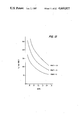
- FIG. 7 is a plot of exposure velocity through magnification range for the variable precession system.
- FIG. 8 is a plot of values document change time through a magnification range for the variable precession system.
- FIG. 9 is a top perspective view of the mechanical drive arrangement for moving the document scan and precession scan components in a second, constant precession, configuration.
- FIG. 10 is a simplified side view of the drive arrangement of FIG. 2.
- FIG. 11 is a control logic block diagram for controlling the scan operations of the constant precession system.
- FIG. 12 is a plot of scan speed through a magnification range at different precession ratios for a constant precession system.
- FIG. 13 is a plot of values of document change time through a magnification range at different precession ratios.
- FIG. 1 schematically depicts the various components of an illustrative electrophotographic printing machine incorporating the optical precession scanning system of the present invention therein. It will become apparent from the following discussion that this optical system is equally well suited for use in a wide variety of electrophotographic printing machines and is not necessarily limited in its application to the particular embodiment shown herein.
- the electrophotographic printing machine uses a photoreceptor belt 10 having a photoconductive surface 12 formed on a conductive substrate.
- belt 10 has characteristics disclosed in U.S. Pat. No. 4,265,990 whose contents are hereby incorporated by reference.
- Belt 10 moves in the indicated direction, advancing sequentially through the various xerographic process stations.
- the belt is entrained about drive roller 16 and tension rollers 18, 20.
- Roller 16 is driven by motor means described in detail below.
- a portion of belt 10 passes through a charging station where a corona generating device, indicated generally by the reference numeral 22, charges photoconductive surface 12 to a relatively high, substantially uniform, negative potential.
- Device 22 comprises a charging electrode 24 and a conductive shield 26.
- An original document 30 is positioned, either manually, or by a document feeder mechanism (not shown) on the surface of a transparent platen 32.
- the document is scanned and reproduced at the photoreceptor by a double dual rate scanning system comprising an object side scan system 34 and an image side scan system 36.
- the optical components included in scan system 34 are illumination scan assembly 40, comprising illumination lamp 42, lamp reflector 44 and full rate scan mirror 46, all three mounted on full rate scan carriage 48.
- Carriage 48 is moved at a first scanning speed V 1 in a plane parallel to that of platen 32 and from right to left. Lamp 42 illuminates incremental line portions of document 30 during the scan cycle.
- the reflected image is reflected by scan mirror 46 to half rate roof mirror assembly 50 mounted on half rate carriage 52.
- Carriage 52 is driven at 1/2 rate of carriage 48 or at a speed V 1/2 .
- Assembly 50 and carriage 52 complete the optical components included in the object side scan system 34.
- the document line image is projected by lens 54, mounted on lens carriage 56 onto a second, full rate roof mirror assembly 58 mounted on half rate carriage 60.
- the image is reflected from assembly 58 to belt mirror 62, mounted on carriage 64 driven during scan at a speed V 3 .
- Carriage 60 is driven at a speed V 3 -V 4/2 .
- Mirror 62 is thus moving in a direction opposite the movement of belt 10 and during scan precesses the document image along the belt surface.
- Belt 10 is moved at a fifth rate V 5 corresponding to the system process speed (up to 75 cpm for the variable speed configuration).
- Belt 10 is driven by main drive motor 65 via pulley 66 (FIG. 3).
- lens 54 is moved to the appropriate magnification position with the mirror components at the selected start-of-scan positions.
- a portion AC of belt 10, representing a distance equal to document length P 1 -P 2 (not shown to scale in the figure) will be exposed during the scan cycle with point C defining the image point of document point P 1 .
- Scan carriage 48 moves from right to left at a scan velocity V 1 .
- Roof assembly 50 moves at a second velocity V 2 , which, is equal to V 1/2 , to maintain a constant object-to-lens distance.
- a reflected image of the document represented by a principal ray 63, is imaged through lens 54 and folded by corner mirror assembly 58 moving from left to right at velocity V 3 .
- the image is then reflected onto belt 10 by mirror 62, moving at V 4 (2 V 3 ) so that the image is precessed during scan a distance equal to BC.
- Point A reaches point B at the end-of-scan position.
- a magnetic brush development system advances an insulating development material into contact with the electrostatic latent image.
- magnetic brush development system 70 includes a developer roller 72 within a housing 74.
- Roller 72 transports a brush of developer material comprising magnetic carrier granules and toner particles into contact with belt 10.
- Roller 72 is positioned so that the brush of developer material deforms belt 10 in an arc with the belt conforming, at least partially, to the configuration of the developer roller.
- the thickness of the layer of developer material adhering to developer roller 72 is adjustable.
- the electrostatic latent image attracts the toner particles from the carrier granules forming a toner powder image on photoconductive surface 12.
- the detailed structure of the magnetic brush development system is more fully disclosed in U.S. Pat. No. 4,397,264, whose contents are hereby incorporated by reference.
- an output copy sheet 80 taken from a supply tray 82 is moved into contact with the toner powder image at a transfer station which includes a corona generating device 84 which sprays ions onto the backside of sheet 80, thereby attracting the toner powder image from surface 12 to sheet 80.
- a transfer station which includes a corona generating device 84 which sprays ions onto the backside of sheet 80, thereby attracting the toner powder image from surface 12 to sheet 80.
- the sheet advances to fusing roller assembly 89, which affixes the transferred powder image.
- sheet 80 advances to an output tray (not shown) for subsequent removal by the operator.
- the residual toner particles and the toner particles of developed test patch areas are removed at cleaning station 86.
- a discharge lamp floods surface 12 with light to dissipate any residual charge remaining thereon prior to the charging thereof for the next imaging cycle.
- the electrophotographic printing machine shown generally in FIG. 1 can be operated as either a medium process speed system (up to 75 cpm) or at a high process speed system (75-110 cpm).
- the medium speed system for ease of description, has been designated as a variable precession system. Its main characteristic is that the scanning components of the object and image side scan system 34, 36 are driven by a common drive means and hence a precession ratio P RAT which is defined as P RAT V 4 /V 5 and which varies directly with magnification.
- the higher speed system has been designated as a constant precession system.
- the object and image side scan systems are decoupled with the image side system driven at a constant speed derived as a function of the photoreceptor speed.
- a description of the variable precession drive system at 1X and at magnification is provided below, followed by a description of the constant precession drive system at 1X and magnification.
- FIGS. 2 and 3 there is shown a top perspective view of the drive system for object and image side scan systems 34, 36. It is assumed that an 81/2 ⁇ 11 document is to be copied at 1:1 magnification ratio in a variable precession mode.
- FIG. 4 illustrates the circuit and logic elements which generate signals to the various scan components based on operator selections at the machine control panel 88 or paper tray 82. The inputs are processed by controller 89 and signals sent to the appropriate components.
- Selection of a print operation at the machine control panel 88 generates an electrical signal which is sent to a scan servo drive motor 90 via controller 89.
- Motor shaft 92 drives timing belt 94 which is entrained about capstan pulley 96 attached to drive shaft 98.
- a second capstan pulley 96' is connected to the other end of shaft 98.
- Cables 100, 100' are entrained about idler pulleys 102, 102' and half rate pulleys 104, 104' with both ends connected to ground.
- the speed of carriage is divided in half by the pulley 104 so that half rate carriage 52, upon which is mounted corner mirror assembly 50, is moving at a speed of V 1/2 .
- the scan movements of the optical components comprising the object scan side system 34 are seen to derive directly from the input shaft 98.
- the drive for the image scan system 36 is derived from the rotation of drive shaft 98 via a pulley 110, mounted on the output end of shaft 98.
- Belt 112 is entrained about pulley 110 and about pulley 115 mounted on the end of image side scan drive shaft 116.
- Cables 118, 118' are entrained about full rate capstan pulleys 114, 114', idler pulleys 120, 120', half rate pulleys 122, 122', and magnification change pulleys 124, 124', 126, 126' in a closed loop drive system.
- the drive movement of shaft 98 is translated into a new set of scan speed relationships determined by the pulley diameter ratio of pulleys 96 and 115.
- carriage 64 upon which is mounted precession mirror 62, is moved at a speed of V 4 (2V 3 ) while roof mirror carriage 60, upon which is mounted corner mirror assembly 58, is moved at speed V 3 .
- the start-of-scan operation is initiated with the object and image scan systems in the solid line positions shown in FIGS. 2, 3.
- a portion AC of belt 60 equal to document length P 1 , P 2 will be exposed during the scan cycle with point C defining the image point of object point P 1 .
- Scan servo motor 90 is driven at a rate previously determined relative to the process speed for the particular system and for a time duration dependent upon the length of the document being copied. The precess condition requires that V 1 >V 5 .
- Full rate scan carriage 48 is driven at a scan rate V 1 which is called the exposure speed and is defined by the expressions
- Half rate carriage 52 moves in the scan direction at a rate V 1/2 .
- Half rate scan carriage 60 is moved in the indicated direction at a rate V 4/2 .
- the document image is reflected onto the surface 12 of photoreceptor 10 in a precess direction opposite the movement of the belt 10 and along a precession distance equal to BC.
- the belt moves so that point A reaches point B at the end-of-scan position. This distance AB is defined by the expression
- scan motor 90 When the scan components reach the end of scan position (mirrors 46, 62 in dotted line position) scan motor 90 reverses directional rotation and the components are returned to the start-of-scan positions.
- a change in magnification from 1X at the control panel 82 generates a signal to controller 89 which in turn, generates the signals which drive lens carriage step under 130, and hence lens carriage 56, along the optical path and to make adjustments for the change in total conjugate length.
- Servo motor 90 will be driven at a faster rate of speed (for reduction) or a slower rate of speed (for enlargement) relative to 1X scanning speed.
- Lens carriage stepper motor 130 (FIG. 4) will be driven to move lens carriage 56 along the optical path to a new position consistent with the required magnification. Movement of the lens to a new position changes the total conjugate (TC) (distance between the platen and photoreceptor) in accordance with the expression.
- FIG. 5 illustrates a typical velocity profile over a scan cycle. Exposure time, represented by t EXP is obtained by the expression ##EQU1##
- the image side scan system 36 is directly coupled to object side scan system. A change in the scan speeds on the object side is reflected in changes in the image side.
- the precession ratio is a function of magnification
- the scan velocities are dependent on original document size and output sheet size.
- variable precession system becomes constrained as process speeds exceed 75 cpm. For example, if the system shown in FIGS. 2, 3 were to be used in a copying machine having an 80-90 cpm rate, a maximum scan velocity V 1 of 80 in/sec (203.2 cm/sec) would have to be achieved. This would require prescan accelerations of up to 4 g's and a rescan time of 0.225 sec.
- FIGS. 9 and 10 An exemplary constant precession system is shown in FIGS. 9 and 10.
- FIG. 11 is a logic control diagram for this system. Referring to these figures, FIG. 9 is identical to FIG. 2 except that object side scan system 34 is decoupled from image side scan system 36; e.g. pulleys 110, and cables 112, are omitted.
- FIG. 10 has been modified by adding a constant precession drive system 140 shown in a top partial perspective, relative to the side perspective view of those same components which remain the same.
- main drive motor 65 has an output drive pulley 142 attached to its shaft.
- Pulley drives a photoreceptor pulley cable 144 attached to the shaft of photoreceptor drive roller 16.
- Pulley cable 144 is entrained about a third component, scan clutch pulley 146 attached to a shaft 148.
- a scan clutch 150 is operatively connected to pulley 152 at the other end of shaft 148.
- pulley 152 drives image side scan pulley 114', at a scan rate determined by the diameter of pulleys 114, 142, 146, 154.
- the clutch is disengaged at the end of scan; simultaneously, dc motor 154 is activated and drives shaft 116 via pulley 114' in the rescan direction by means of rescan cable 156.
- the operation of the object side scan system of constant precession system of FIGS. 10, 11 is essentially the same as for the variable precession system, both for 1X and for variable magnification.
- the object and image side systems 34, 36 are in the solid line positions shown in FIG. 10.
- Scan servo motor 90 drives full rate carriage 48 at a previously determined scan speed V 1 .
- Half rate carriage 52 moves in the scan direction at a rate V 1/2 .
- Photoreceptor belt 10 is driven in the indicated direction at a V 5 rate.
- Image side full rate carriage 64 is moved from left to right at a third rate V 4 which is defined by the expression
- the document image is laid down in the process direction along a precession distance BC. This distance is different than the variable precession case.
- scan clutch 150 is disengaged, rescan motor 154 is started and the image side optical system components are returned to the start-of-scan position. Clutch 150 is energized with the next copy cycle.
- a change in magnification from 1X at the control panel generates a signal to controller 89 which, in turn, generates the signals required to move lens carriage 56 along the optical path.
- the image side scan system 36 is decoupled from the object side scan system 34.
- the image side system optics is driven at a rate proportional to the photoreceptor rate V 5 .
- the precession ratio P RAT is not a function of magnification; e.g. P RAT ⁇ f(m).
- the precession scan (image side) maximum travels are dependent on output sheet size.
Abstract
Description
V.sub.1 =1+(V.sub.4 /V.sub.5)V.sub.5 V.sub.5 +V.sub.4 (1)
AB=(P.sub.1 P.sub.2 /V.sub.1)V.sub.5 (2)
TC=F(M+1)+F(1+1/M)
AC=MP.sub.1 P.sub.2 (3)
t.sub.RET =t.sub.DCT -t.sub.dwell -t.sub.pre (6)
______________________________________
scan speed V.sub.1 =
                  17.5 in/sec (44.45 cm/sec)
photoreceptor speed V.sub.5 =
                  10.5 in/sec (26.67 cm/sec)
precess scan speed V.sub.4 =
                   7.0 in/sec (17.78 cm/sec)
precession distance BC =
                   7.0 in/sec (17.78 cm/sec)
prescan acceleration
                   2.0 g's
return time =      .375 sec
document change time =
                   .514 sec
precession ratio (P.sub.RAT) =
                   .6667
exposure time =    .486 sec
R =                3.0
______________________________________
(P.sub.RAT =1/(MR-1)).
V.sub.V =P.sub.RAT *V.sub.5
______________________________________
scan speed V.sub.1 =
                   30.0 in/sec (76.2 cm/sec)
process speed V.sub.5 =
                   16.5 in/sec (41.91 cm/sec)
precess scan speed V.sub.3 or V.sub.4 =
                   13.5 in/sec (34.29 cm/sec)
precession distance BC =
                    4.7 in (11.94 cm)
prescan acceleration =
                    2.0 g's
return time =       .245 sec
document change time =
                    .360 sec
precession ratio (P.sub.RAT) =
                    .82
exposure time =     .283 sec
______________________________________
Claims (9)
Priority Applications (4)
| Application Number | Priority Date | Filing Date | Title |
|---|---|---|---|
| US06/748,072 US4669857A (en) | 1985-06-24 | 1985-06-24 | Double dual rate precession scan system |
| JP61141213A JPH0746203B2 (en) | 1985-06-24 | 1986-06-17 | Double dual rate scanning device |
| DE8686304848T DE3677836D1 (en) | 1985-06-24 | 1986-06-24 | DOUBLE-SPEED SYSTEM FOR CONTINUOUS LINEAL SCANNING WITH TWO SPEEDS. |
| EP86304848A EP0207711B1 (en) | 1985-06-24 | 1986-06-24 | Double dual rate precession scan system |
Applications Claiming Priority (1)
| Application Number | Priority Date | Filing Date | Title |
|---|---|---|---|
| US06/748,072 US4669857A (en) | 1985-06-24 | 1985-06-24 | Double dual rate precession scan system |
Publications (1)
| Publication Number | Publication Date |
|---|---|
| US4669857A true US4669857A (en) | 1987-06-02 |
Family
ID=25007877
Family Applications (1)
| Application Number | Title | Priority Date | Filing Date |
|---|---|---|---|
| US06/748,072 Expired - Lifetime US4669857A (en) | 1985-06-24 | 1985-06-24 | Double dual rate precession scan system |
Country Status (4)
| Country | Link |
|---|---|
| US (1) | US4669857A (en) |
| EP (1) | EP0207711B1 (en) |
| JP (1) | JPH0746203B2 (en) |
| DE (1) | DE3677836D1 (en) |
Families Citing this family (2)
| Publication number | Priority date | Publication date | Assignee | Title |
|---|---|---|---|---|
| US4687317A (en) * | 1986-06-12 | 1987-08-18 | Xerox Corporation | Document scanning system with selective edit mode |
| DE10122484A1 (en) | 2001-05-09 | 2002-11-28 | Heidelberger Druckmasch Ag | Method and device for exposing printing forms |
Citations (8)
| Publication number | Priority date | Publication date | Assignee | Title |
|---|---|---|---|---|
| US3542467A (en) * | 1968-04-15 | 1970-11-24 | Xerox Corp | Xerographic reproducing apparatus |
| US3614222A (en) * | 1970-04-24 | 1971-10-19 | Olivetti & Co Spa | Optical drive system for reproducing machine |
| US4265990A (en) * | 1977-05-04 | 1981-05-05 | Xerox Corporation | Imaging system with a diamine charge transport material in a polycarbonate resin |
| US4336995A (en) * | 1980-09-24 | 1982-06-29 | Xerox Corporation | Precession scanning system for copier device |
| US4351605A (en) * | 1981-05-11 | 1982-09-28 | Xerox Corporation | Controlled velocity transport precession system |
| US4362382A (en) * | 1981-02-23 | 1982-12-07 | Xerox Corporation | Precession scanning system |
| US4397264A (en) * | 1980-07-17 | 1983-08-09 | Xerox Corporation | Electrostatic image development system having tensioned flexible recording member |
| US4484810A (en) * | 1983-05-20 | 1984-11-27 | Xerox Corporation | Moving platen precession system |
Family Cites Families (4)
| Publication number | Priority date | Publication date | Assignee | Title |
|---|---|---|---|---|
| US3841753A (en) * | 1971-08-02 | 1974-10-15 | Minolta Camera Kk | Scanning system |
| US4372670A (en) * | 1981-02-23 | 1983-02-08 | Xerox Corporation | Precession scanning system |
| JPS5821274A (en) * | 1981-07-31 | 1983-02-08 | Fuji Xerox Co Ltd | Scanning and exposing device for copying machine |
| US4585331A (en) * | 1984-08-20 | 1986-04-29 | Xerox Corporation | Optical scanning system utilizing linear drive motors |
-
1985
- 1985-06-24 US US06/748,072 patent/US4669857A/en not_active Expired - Lifetime
-
1986
- 1986-06-17 JP JP61141213A patent/JPH0746203B2/en not_active Expired - Fee Related
- 1986-06-24 EP EP86304848A patent/EP0207711B1/en not_active Expired - Lifetime
- 1986-06-24 DE DE8686304848T patent/DE3677836D1/en not_active Expired - Fee Related
Patent Citations (8)
| Publication number | Priority date | Publication date | Assignee | Title |
|---|---|---|---|---|
| US3542467A (en) * | 1968-04-15 | 1970-11-24 | Xerox Corp | Xerographic reproducing apparatus |
| US3614222A (en) * | 1970-04-24 | 1971-10-19 | Olivetti & Co Spa | Optical drive system for reproducing machine |
| US4265990A (en) * | 1977-05-04 | 1981-05-05 | Xerox Corporation | Imaging system with a diamine charge transport material in a polycarbonate resin |
| US4397264A (en) * | 1980-07-17 | 1983-08-09 | Xerox Corporation | Electrostatic image development system having tensioned flexible recording member |
| US4336995A (en) * | 1980-09-24 | 1982-06-29 | Xerox Corporation | Precession scanning system for copier device |
| US4362382A (en) * | 1981-02-23 | 1982-12-07 | Xerox Corporation | Precession scanning system |
| US4351605A (en) * | 1981-05-11 | 1982-09-28 | Xerox Corporation | Controlled velocity transport precession system |
| US4484810A (en) * | 1983-05-20 | 1984-11-27 | Xerox Corporation | Moving platen precession system |
Non-Patent Citations (1)
| Title |
|---|
| U.S. Ser. No. 642,272, Stoffel et al. filed 08/1984. * |
Also Published As
| Publication number | Publication date |
|---|---|
| DE3677836D1 (en) | 1991-04-11 |
| JPH0746203B2 (en) | 1995-05-17 |
| JPS61295543A (en) | 1986-12-26 |
| EP0207711B1 (en) | 1991-03-06 |
| EP0207711A1 (en) | 1987-01-07 |
Similar Documents
| Publication | Publication Date | Title |
|---|---|---|
| US4209248A (en) | Continuously variable reduction copier optics systems | |
| US4403848A (en) | Electronic color printing system | |
| US4501490A (en) | Copying apparatus | |
| US4120578A (en) | Continuously variable reduction scanning optics drive | |
| US4459010A (en) | Linear lens array scanning system for a multi-magnification copier | |
| US4084897A (en) | Half-lens/mirror copier providing original-to-copy image reduction | |
| US4669857A (en) | Double dual rate precession scan system | |
| EP0411865A2 (en) | An image forming apparatus | |
| US5097290A (en) | Scanner for scanning an object from a plurality of positions | |
| JPH0785162B2 (en) | Image forming apparatus for copier | |
| JPS58114070A (en) | Electrophotographic device | |
| GB2085608A (en) | Line-by-line photocopying | |
| US4367942A (en) | Xerographic copying machine | |
| US4643560A (en) | Apparatus and method for synchronizing exposure of a document onto a photosensitive member | |
| JPS6131458B2 (en) | ||
| US4351605A (en) | Controlled velocity transport precession system | |
| US4514081A (en) | Image making system and apparatus therefor | |
| US4461565A (en) | Optical scanning device | |
| US4374619A (en) | Variable magnification copying apparatus | |
| US4589759A (en) | Reproducing apparatus with optic scanning module | |
| US4897688A (en) | Document imaging system with bi-directional anamorphic magnification capability | |
| US4511236A (en) | Electrophotographic process | |
| EP0615171B1 (en) | Variable magnification copying apparatus | |
| JPS61221736A (en) | Copying device | |
| JPH0476574A (en) | Exposure optical system for copying machine |
Legal Events
| Date | Code | Title | Description |
|---|---|---|---|
| AS | Assignment |
Owner name: XEROX CORPORATION STAMFORD, CT A CORP OF NY Free format text: ASSIGNMENT OF ASSIGNORS INTEREST.;ASSIGNORS:SPINELLI, RICHARD A.;COSTANZA, DANIEL W.;STATT, WILLIAM L.;AND OTHERS;REEL/FRAME:004427/0870 Effective date: 19850619 |
|
| STCF | Information on status: patent grant |
Free format text: PATENTED CASE |
|
| FEPP | Fee payment procedure |
Free format text: PAYOR NUMBER ASSIGNED (ORIGINAL EVENT CODE: ASPN); ENTITY STATUS OF PATENT OWNER: LARGE ENTITY |
|
| FPAY | Fee payment |
Year of fee payment: 4 |
|
| FPAY | Fee payment |
Year of fee payment: 4 |
|
| FPAY | Fee payment |
Year of fee payment: 8 |
|
| FPAY | Fee payment |
Year of fee payment: 12 |
|
| AS | Assignment |
Owner name: BANK ONE, NA, AS ADMINISTRATIVE AGENT, ILLINOIS Free format text: SECURITY INTEREST;ASSIGNOR:XEROX CORPORATION;REEL/FRAME:013153/0001 Effective date: 20020621 |
|
| AS | Assignment |
Owner name: JPMORGAN CHASE BANK, AS COLLATERAL AGENT, TEXAS Free format text: SECURITY AGREEMENT;ASSIGNOR:XEROX CORPORATION;REEL/FRAME:015134/0476 Effective date: 20030625 Owner name: JPMORGAN CHASE BANK, AS COLLATERAL AGENT,TEXAS Free format text: SECURITY AGREEMENT;ASSIGNOR:XEROX CORPORATION;REEL/FRAME:015134/0476 Effective date: 20030625 |
|
| AS | Assignment |
Owner name: XEROX CORPORATION, CONNECTICUT Free format text: RELEASE BY SECURED PARTY;ASSIGNOR:JPMORGAN CHASE BANK, N.A. AS SUCCESSOR-IN-INTEREST ADMINISTRATIVE AGENT AND COLLATERAL AGENT TO JPMORGAN CHASE BANK;REEL/FRAME:066728/0193 Effective date: 20220822 |