US4676353A - Lock-up torque converter control combined with anti-skid brake control - Google Patents
Lock-up torque converter control combined with anti-skid brake control Download PDFInfo
- Publication number
- US4676353A US4676353A US06/666,446 US66644684A US4676353A US 4676353 A US4676353 A US 4676353A US 66644684 A US66644684 A US 66644684A US 4676353 A US4676353 A US 4676353A
- Authority
- US
- United States
- Prior art keywords
- lock
- skid
- vehicle
- wheel
- control means
- Prior art date
- Legal status (The legal status is an assumption and is not a legal conclusion. Google has not performed a legal analysis and makes no representation as to the accuracy of the status listed.)
- Expired - Fee Related
Links
- 230000009471 action Effects 0.000 claims abstract description 13
- 230000007423 decrease Effects 0.000 claims description 17
- 230000007246 mechanism Effects 0.000 claims description 16
- 239000012530 fluid Substances 0.000 claims description 15
- 230000001960 triggered effect Effects 0.000 claims description 13
- 230000008859 change Effects 0.000 claims description 10
- 230000005540 biological transmission Effects 0.000 claims description 9
- 230000003247 decreasing effect Effects 0.000 claims 2
- 239000003112 inhibitor Substances 0.000 claims 2
- 230000001133 acceleration Effects 0.000 description 6
- 238000001514 detection method Methods 0.000 description 3
- 238000010586 diagram Methods 0.000 description 2
- 239000000470 constituent Substances 0.000 description 1
- 230000009849 deactivation Effects 0.000 description 1
- 230000007257 malfunction Effects 0.000 description 1
- 230000000737 periodic effect Effects 0.000 description 1
- 230000004044 response Effects 0.000 description 1
Images


Classifications
-
- F—MECHANICAL ENGINEERING; LIGHTING; HEATING; WEAPONS; BLASTING
- F16—ENGINEERING ELEMENTS AND UNITS; GENERAL MEASURES FOR PRODUCING AND MAINTAINING EFFECTIVE FUNCTIONING OF MACHINES OR INSTALLATIONS; THERMAL INSULATION IN GENERAL
- F16H—GEARING
- F16H45/00—Combinations of fluid gearings for conveying rotary motion with couplings or clutches
- F16H45/02—Combinations of fluid gearings for conveying rotary motion with couplings or clutches with mechanical clutches for bridging a fluid gearing of the hydrokinetic type
-
- B—PERFORMING OPERATIONS; TRANSPORTING
- B60—VEHICLES IN GENERAL
- B60T—VEHICLE BRAKE CONTROL SYSTEMS OR PARTS THEREOF; BRAKE CONTROL SYSTEMS OR PARTS THEREOF, IN GENERAL; ARRANGEMENT OF BRAKING ELEMENTS ON VEHICLES IN GENERAL; PORTABLE DEVICES FOR PREVENTING UNWANTED MOVEMENT OF VEHICLES; VEHICLE MODIFICATIONS TO FACILITATE COOLING OF BRAKES
- B60T8/00—Arrangements for adjusting wheel-braking force to meet varying vehicular or ground-surface conditions, e.g. limiting or varying distribution of braking force
- B60T8/17—Using electrical or electronic regulation means to control braking
- B60T8/176—Brake regulation specially adapted to prevent excessive wheel slip during vehicle deceleration, e.g. ABS
- B60T8/1761—Brake regulation specially adapted to prevent excessive wheel slip during vehicle deceleration, e.g. ABS responsive to wheel or brake dynamics, e.g. wheel slip, wheel acceleration or rate of change of brake fluid pressure
- B60T8/17616—Microprocessor-based systems
-
- B—PERFORMING OPERATIONS; TRANSPORTING
- B60—VEHICLES IN GENERAL
- B60T—VEHICLE BRAKE CONTROL SYSTEMS OR PARTS THEREOF; BRAKE CONTROL SYSTEMS OR PARTS THEREOF, IN GENERAL; ARRANGEMENT OF BRAKING ELEMENTS ON VEHICLES IN GENERAL; PORTABLE DEVICES FOR PREVENTING UNWANTED MOVEMENT OF VEHICLES; VEHICLE MODIFICATIONS TO FACILITATE COOLING OF BRAKES
- B60T8/00—Arrangements for adjusting wheel-braking force to meet varying vehicular or ground-surface conditions, e.g. limiting or varying distribution of braking force
- B60T8/32—Arrangements for adjusting wheel-braking force to meet varying vehicular or ground-surface conditions, e.g. limiting or varying distribution of braking force responsive to a speed condition, e.g. acceleration or deceleration
- B60T8/321—Arrangements for adjusting wheel-braking force to meet varying vehicular or ground-surface conditions, e.g. limiting or varying distribution of braking force responsive to a speed condition, e.g. acceleration or deceleration deceleration
- B60T8/3215—Systems characterised by having means acting on components of the drive line, e.g. retarder, clutch or differential gear
-
- B—PERFORMING OPERATIONS; TRANSPORTING
- B60—VEHICLES IN GENERAL
- B60W—CONJOINT CONTROL OF VEHICLE SUB-UNITS OF DIFFERENT TYPE OR DIFFERENT FUNCTION; CONTROL SYSTEMS SPECIALLY ADAPTED FOR HYBRID VEHICLES; ROAD VEHICLE DRIVE CONTROL SYSTEMS FOR PURPOSES NOT RELATED TO THE CONTROL OF A PARTICULAR SUB-UNIT
- B60W10/00—Conjoint control of vehicle sub-units of different type or different function
- B60W10/02—Conjoint control of vehicle sub-units of different type or different function including control of driveline clutches
-
- B—PERFORMING OPERATIONS; TRANSPORTING
- B60—VEHICLES IN GENERAL
- B60W—CONJOINT CONTROL OF VEHICLE SUB-UNITS OF DIFFERENT TYPE OR DIFFERENT FUNCTION; CONTROL SYSTEMS SPECIALLY ADAPTED FOR HYBRID VEHICLES; ROAD VEHICLE DRIVE CONTROL SYSTEMS FOR PURPOSES NOT RELATED TO THE CONTROL OF A PARTICULAR SUB-UNIT
- B60W10/00—Conjoint control of vehicle sub-units of different type or different function
- B60W10/18—Conjoint control of vehicle sub-units of different type or different function including control of braking systems
- B60W10/184—Conjoint control of vehicle sub-units of different type or different function including control of braking systems with wheel brakes
-
- B—PERFORMING OPERATIONS; TRANSPORTING
- B60—VEHICLES IN GENERAL
- B60W—CONJOINT CONTROL OF VEHICLE SUB-UNITS OF DIFFERENT TYPE OR DIFFERENT FUNCTION; CONTROL SYSTEMS SPECIALLY ADAPTED FOR HYBRID VEHICLES; ROAD VEHICLE DRIVE CONTROL SYSTEMS FOR PURPOSES NOT RELATED TO THE CONTROL OF A PARTICULAR SUB-UNIT
- B60W30/00—Purposes of road vehicle drive control systems not related to the control of a particular sub-unit, e.g. of systems using conjoint control of vehicle sub-units, or advanced driver assistance systems for ensuring comfort, stability and safety or drive control systems for propelling or retarding the vehicle
- B60W30/18—Propelling the vehicle
- B60W30/18172—Preventing, or responsive to skidding of wheels
-
- B—PERFORMING OPERATIONS; TRANSPORTING
- B60—VEHICLES IN GENERAL
- B60W—CONJOINT CONTROL OF VEHICLE SUB-UNITS OF DIFFERENT TYPE OR DIFFERENT FUNCTION; CONTROL SYSTEMS SPECIALLY ADAPTED FOR HYBRID VEHICLES; ROAD VEHICLE DRIVE CONTROL SYSTEMS FOR PURPOSES NOT RELATED TO THE CONTROL OF A PARTICULAR SUB-UNIT
- B60W30/00—Purposes of road vehicle drive control systems not related to the control of a particular sub-unit, e.g. of systems using conjoint control of vehicle sub-units, or advanced driver assistance systems for ensuring comfort, stability and safety or drive control systems for propelling or retarding the vehicle
- B60W30/18—Propelling the vehicle
- B60W30/1819—Propulsion control with control means using analogue circuits, relays or mechanical links
-
- F—MECHANICAL ENGINEERING; LIGHTING; HEATING; WEAPONS; BLASTING
- F16—ENGINEERING ELEMENTS AND UNITS; GENERAL MEASURES FOR PRODUCING AND MAINTAINING EFFECTIVE FUNCTIONING OF MACHINES OR INSTALLATIONS; THERMAL INSULATION IN GENERAL
- F16H—GEARING
- F16H61/00—Control functions within control units of change-speed- or reversing-gearings for conveying rotary motion ; Control of exclusively fluid gearing, friction gearing, gearings with endless flexible members or other particular types of gearing
- F16H61/14—Control of torque converter lock-up clutches
- F16H61/143—Control of torque converter lock-up clutches using electric control means
Definitions
- the present invention relates to a system for controlling a lock-up torque converter of an automatic transmission mounted on a vehicle equipped with an anti-skid brake control system (a wheel slip brake control system).
- an anti-skid brake control system a wheel slip brake control system
- Japanese Patent provisional publications Nos. 54-132062, 55-109854 and 56-127856 disclose lock-up torque converters having a lock-up clutch disposed between input and output members of a hydrodynamic drive to provide a direct mechanical drive.
- the lock-up clutch is controlled by a control unit in accordance with a vehicle speed determined from an output signal of a wheel speed sensor or the like.
- a lock-up vehicle speed and a release vehicle speed equal to or lower than the lock-up vehicle speed are predetermined for each gear position of the transmission.
- the control unit makes the lock-up clutch engage by sending a lock-up control signal to a lock-up solenoid for switching hydraulic fluid passage in the torque converter.
- the control unit deactivates the lock-up solenoid, so that the lock-up clutch is disengaged.
- there is some delay normally, about 0.2 to 0.3 second) between the deactivation of the lock-up solenoid and the complete disengagement of the lock-up clutch because the lock-up clutch is operated by the hydraulic system. Consequently, there is a possibility that during hard braking the vehicle speed will decrease into an engine stall range before the lock-up clutch is disengaged.
- Japanese Patent provisional publication No. 57-192668 proposes an lock-up torque converter control system arranged to prevent engine stall during hard braking.
- the lock-up clutch is controlled in accordance with not only the vehicle speed but also the deceleration. If the deceleration exceeds a predetermined value, the control unit of this control system commands the lock-up solenoid to disengage the lock-up clutch even before the vehicle speed decreases to the predetermined release speed.
- this lock-up torque converter control system is not satisfactory when it is applied to a vehicle equipped with an anti-skid brake control system.
- a vehicle comprises a brake system, condition detecting means for detecting a running condition of the vehicle, anti-skid brake control means, an automatic transmission having a torque converter and a lock-up mechanism to provide a direct mechanical drive, lock-up actuating means for actuating the lock-up mechanism, lock-up control means, and lock-up inhibit means.
- the anti-skid brake control means is connected with the condition detecting means for automatically controlling a brake actuation force during braking in accordance with the running condition detected by the condition detecting means.
- the lock-up mechanism is engaged so that power can be transmitted through the mechanical drive when the lock-up actuating means is in a lock-up state.
- the lock-up mechanism is disengaged so that power cannot be transmitted through the mechanical drive when the lock-up actuating means is in a release state.
- the lock-up control means is connected with the condition detecting means for engaging and disengaging the lock-up mechanism by putting the lock-up actuating means in the lock-up state and in the release state in accordance with the running condition detected by the condition detecting means.
- the lock-up inhibit means detects the operation of the anti-skid control means and holds the lock-up actuating means in the release state by preventing the control action of the lock-up control means while the anti-skid control means is controlling the brake actuation force.
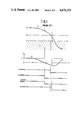
- FIGS. 1 and 2 are timing charts for showing the behavior of a conventional lock-up torque converter control system
- FIG. 3 is a block diagram showing one embodiment of the present invention.
- FIG. 4 is a timing chart showing the operation of the control system of FIG. 3;
- FIG. 5 is a view of a hydraulic circuit of an anti-skid brake control system used in the embodiment of the present invention.
- FIG. 6 is a view showing the anti-skid brake control circuit shown in FIG. 5.
- FIG. 1 shows the operation of the lock-up torque converter control system of Japanese Patent provisional publication No. 57-192668 mentioned above.
- the lock up control signal is shut off or changed to the low level before the vehicle speed Vw reaches a predetermined release vehicle speed Vs if the deceleration exceeds a predetermined value - ⁇ b. Therefore, in spite of a delay between the change of the lock-up control signal and the disengagement of the lock-up clutch, the lock-up clutch is disengaged before the vehicle speed reaches an engine stall range A below an engine stall vehicle speed Vd.
- FIG. 2 shows the behizate of the lock-up torque converter control system of FIG. 1, applied to a vehicle equipped with an anti-skid brake control system.
- the vehicle speed and the deceleration are determined by detecting the wheel speed.
- the wheel speed Vw oscillates largely (in such a manner that the wheel acceleration ⁇ w oscillates from about -20 G to about 10 G) with a very short period (about 0.5 second) during the operation of the anti-skid brake control system. Therefore, there still remains a possibility that the engine of the vehicle stalls because of a rapid decrease of the wheel speed before disengagement of the lock-up clutch, especially when the wheel speed is in a low wheel speed range (from an instant t 3 to an instant t 5 in FIG.
- FIG. 3 One embodiment of the present invention is shown in the block diagram of FIG. 3.
- the present invention is applied to a front engine rear wheel drive vehicle having three anti-skid brake control (wheel slip brake control) systems for a right front wheel, a left front wheel and rear wheels.
- anti-skid brake control wheel slip brake control
- This vehicle has a right front wheel speed sensor 2a for a right front wheel 1a, a left front wheel speed sensor 2b for a left front wheel 1b, and a rear wheel speed sensor 2c for a rear wheel 1c.
- the wheel speed sensors 2a, 2b and 2c are connected, respectively, to anti-skid brake control circuits 3a, 3b and 3c, each of which produces an anti-skid brake control signal (an EV signal and an AV signal).
- the anti-skid brake control circuits 3a, 3b and 3c are connected, respectively, to a right front anti-skid actuator 4a disposed in a hydraulic circuit for the brake of the right front wheel, a left front anti-skid actuator 4b disposed in a hydraulic circuit for the brake of the left front wheel, and a rear anti-skid actuator 4c disposed in a hydraulic circuit for the brakes of the rear wheels.
- the anti-skid actuators 4a, 4b and 4c are identical with one another.
- FIG. 5 shows the actuator 4a, as an example.
- the anti-skid actuator 4a comprises an inlet valve (an EV valve) 106 disposed in a fluid passage for transmitting the brake fluid pressure from a master cylinder 105 to a wheel cylinder 103, and an outlet valve (an AV valve) 107 disposed in a fluid passage for returning the brake fluid pressure from the wheel cylinder 103 to the master cylinder 105 by the aid of a fluid pump 108, an accumulator 109 and a check valve 110.
- Each of the anti-skid brake control circuits 3a, 3b and 3c calculates a wheel speed and a rate of change of the wheel speed with respect to time (acceleration or deceleration) from an output signal of the associated wheel speed sensor 2a, 2b or 2c.
- each of the anti-skid brake control circuits 3a, 3b and 3c produces an anti-skid control signal to control the associated anti-skid actuator 4a, 4b or 4c.
- the anti-skid control signal of each anti-skid control circuit comprises an EV signal to control the inlet valve 106, and and AV signal to control the outlet valve 107.
- the anti-skid control circuits 3a, 3b and 3c are identical with one another.
- FIG. 6 shows the circuit 3a as an example.
- the wheel speed sensor 2a produces an A.C. signal or other periodic signal having a frequency proportional to the rotational speed of the wheel 1a.
- the wheel speed sensor 2a is connected to a wheel speed detecting circuit 202 of the anti-skid brake control circuit 3a.
- the wheel speed detecting circuit 202 is a frequency to voltage converter which provides an output voltage signal proportional to the frequency of the signal of the wheel speed sensor 2a. Accordingly, the outputs signal of the wheel speed detecting circuit 202 is indicative of the wheel speed Vw.
- a deceleration detection circuit 203 receives the voltage signal of the wheel speed detection circuit 202, differentiates the wheel speed Vw, and determines a deceleration ⁇ w of the wheel.
- a comparator 206 compares the deceleration ⁇ w determined by the deceleration detection circuit 203 with a predetermined deceleration b 1 . The output of the comparator 206 rises from a low (L) level to a high (H) level when the absolute valve of the deceleration ⁇ w (which is negative) exceeds the absolute value of the predetermined deceleration b 1 (which is negative).
- a quasi vehicle speed generator 204 generates a target straight line V 0 approximately equal to the actual vehicle speed each time an eb signal, whichis the output signal of from the comparator 206, rises from the low level to the high level because of a decrease of the rate of change of the wheel speed below the predetermined deceleration.
- a desired wheel speed generator 205 multiplies the value of the target line V 0 by a predetermined coefficient, and thereby generates a desired straight line V 1 which defines a boundary between a ⁇ 0 zone (in which the rate of wheel slip is equal to or lower than 15%, for example) and a ⁇ 1 zone (in which the rate of wheel slip is greater than 15%, for example).
- a comparator 207 compares the wheel speed Vw with the desired straight line V 1 .
- the output of the comparator 207 falls from the high level to the low level when the wheel speed Vw exceeds V 1 .
- An AND gate 212 is connected with comparator 207 and a compartor 208. On the condition that the output of the comparator 208 is at the low level, the AND gate 212 provides an output which is in the high level when the vehicle speed is within the ⁇ 1 zone, that is, when the vehicle speed Vw is smaller than V 1 . The output of the AND gate 212 is forced into the low level when the wheel speed Vw exceeds V 1 , that is, when the wheel speed enters the ⁇ 0 zone.
- the comparator 208 compares the wheel deceleration ⁇ w with a predetermined acceleration ⁇ 1 .
- the output of the comparator 208 rises from a low level to a high level when ⁇ w exceeds a 1 .
- the output signals of the comparators 206, 207 and 208 are inputted to an OR gate 209.
- An amplifier 210 receives the output signal of the OR gate 209 and produces the EV signal.
- An amplifier 213 receives the output signal of the AND gate 212 and produces the AV signal.
- the output terminal of the comparator 208 is connected to the OR gate 209 and the AND gate 212 so that, when the acceleration is equal to or greater than the predetermined acceleration a 1 , the high output of the comparator 208 forces the EV signal into the high level and the AV signal into the low level to hold the brake pressure unchanged.
- Each anti-skid actuator 4a, 4b or 4c receives the EV signal and the AV signal from the associated anti-skid control circuit 3a, 3b or 3c. In accordance with the EV and AV signals, each anti-skid actuator decreases, holds unchanged or increases the brake fluid pressure of the associated hydraulic circuit, as shown in Table-1 below.
- Timers 5a, 5b and 5c are connected with the anti-skid control circuits 3a, 3b and 3c, respectively.
- Each of the timers 5a, 5b and 5c is triggered by a rise of the AV signal, and held in an active state for a predetermined time interval (about two seconds) which is equal to or greater than the greatest period of the brake-release cycle of the anti-skid brake control system within a normal range of possibility.
- Each timer is re-triggerable. That is, if one or more trigger signal is applied to the timer while the timer is already in the active state, then the timer is triggered again by each trigger signal and held in the active state until the predetermined time interval starting from the last trigger signal is elapsed.
- the timers 5a, 5b and 5c are connected to an OR gate G whose output signal (which is referred to as MR signal) is normally used to actuate the motor of the pump of each hydraulic circuit for returning the fluid pressure from the wheel cylinder to the master cylinder.
- MR signal output signal
- a lock-up torque converter control circuit 6 controls a lock-up torque converter of an automatic transmission according to the characteristic shown in FIG. 1.
- the lock-up control circuit 6 is connected with the right front wheel speed sensor 2a. From the output signal of the right front wheel speed sensor 2a, the lock-up control circuit 6 calculates the wheel speed and the rate of change of the wheel speed. When the calculated wheel speed reaches a predetermined lock-up vehicle speed, the lock-up control circuit 6 produces a high level lock-up control signal. If the calculated wheel speed decreases to a predetermined release vehicle speed, or if the calculated rate of change of the wheel speed reaches a predetermined deceleration - ⁇ b, the lock-up control circuit 6 changes the lock-up control signal from the high level to the low level.
- the lock-up control signal is applied to the base of a switching transistor Q 1 which is a constituent member of a lock-up actuating circuit 7.
- a switching transistor Q 1 When the switching transistor Q 1 is turned on by the lock-up control signal of the high level, a coil 8a of a lock-up solenoid 8 is energized by a power supply Vcc.
- the output signal of the OR gate G whose inputs are connected with the timers 5a, 5b and 5c is applied to the base of a switching transistor Q 2 .
- the collector of the switching transistor Q 2 is connected with the base of the switching transistor Q 1 .
- the emitter of the switching transistor Q 2 is grounded. When the switching transistor Q 2 is turned on, the base of the switching transistor Q 1 is held in the low level.
- the thus constructed control system is operated as follows:
- the lock-up torque converter is controlled according to the characteristic shown in FIG. 1. If the wheel speed decreases to the release vehicle speed, or if the rate of change of the wheel speed reaches the predetermined deceleration - ⁇ b, the lock-up control circuit 6 changes the lock-up control signal to the low level. In response to the change of the lock-up control signal to the low level, the switching transistor Q 1 is switched off, and the coil 8a of the lock-up solenoid 8 is deenergized. Therefore, the lock-up clutch is disengaged, and the torque converter is released.
- each of the anti-skid brake control circuits 3a, 3b and 3c starts the brake control operation by sending the EV and AV signals to its actuator 4a, 4b or 4c.
- the inlet and outlet valves of each actuator are switched sequentially among the control mode to increase the brake fluid pressure, the control mode to hold the fluid pressure unchanged and the control mode to decrease the fluid pressure, as shown in FIG. 4. Accordingly, the wheel speed Vw decreases while oscilating so that the wheel speed Vw is alternately greater and smaller than the desired wheel speed V 1 at which the brake efficiency is maximum, as shown in FIG. 4.
- each anti-skid brake control circuit 3a, 3b or 3c When the AV signal first rises from the low level to the high level at an instant t 1 shown in FIG. 4 after the start of the control operation of each anti-skid brake control circuit 3a, 3b or 3c, the associated timer 5a, 5b or 5c is first triggered. After that, the timer 5a, 5b or 5c is triggered again each time the AV signal rises at instants t 2 and t 3 . Therefore, each timer is held in the active state to produce the output in the high level during the control operation of the associated anti-skid brake control circuit.
- the switching transistor Q 2 When any one of more of the timers 5a, 5b and 5c is thus brought into the active state, the switching transistor Q 2 is turned on, so that the switching transistor Q 1 is turned off, and the coil 8a of the lock-up solenoid 8 is deenergized.
- the switching transistor Q 1 is in the OFF state as long as any one or more of the timers 5a, 5b and 5c is maintained in the active state.
- the lock-up torque converter is maintained in the released state regardless of the control action of the lock-up control circuit 6 while any one or more of the anti-skid brake control circuits 3a, 3b and 3c is performing its anti-skid brake control operation. Accordingly, the control system of the present invention can prevent engine stall, and maintain the anti-skid brake control in order.
- timers 5a, 5b and 5c are triggered each time the EV signal rises from the low level to the high level. Furthermore, the timers 5a, 5b and 5c may be omitted. In this case, the EV signals of the anti-skid control circuits 3a, 3b and 3c are inputted to an OR gate, whose output is connected to the base of the switching transistor Q 2 .
Abstract
Description
              TABLE 1
______________________________________
        Mode
                       Hold
          Increase     Pressure  Decrease
Signal    Pressure     Unchanged Pressure
______________________________________
EV Signal L            H         H
AV Signal L            L         H
______________________________________
Claims (14)
Applications Claiming Priority (2)
| Application Number | Priority Date | Filing Date | Title |
|---|---|---|---|
| JP58208960A JPS60101356A (en) | 1983-11-09 | 1983-11-09 | Lock-up control device of automatic speed change gear for car |
| JP58-208960 | 1983-11-09 |
Publications (1)
| Publication Number | Publication Date |
|---|---|
| US4676353A true US4676353A (en) | 1987-06-30 |
Family
ID=16564997
Family Applications (1)
| Application Number | Title | Priority Date | Filing Date |
|---|---|---|---|
| US06/666,446 Expired - Fee Related US4676353A (en) | 1983-11-09 | 1984-10-30 | Lock-up torque converter control combined with anti-skid brake control |
Country Status (4)
| Country | Link |
|---|---|
| US (1) | US4676353A (en) |
| EP (1) | EP0148349B1 (en) |
| JP (1) | JPS60101356A (en) |
| DE (1) | DE3475891D1 (en) |
Cited By (16)
| Publication number | Priority date | Publication date | Assignee | Title |
|---|---|---|---|---|
| US4796739A (en) * | 1986-09-10 | 1989-01-10 | Robert Bosch Gmbh | Clutch actuation device |
| US4809508A (en) * | 1986-03-26 | 1989-03-07 | Bendix France | Clutch-disengaging hydraulic actuators preventing wheel slip |
| US4825989A (en) * | 1986-05-09 | 1989-05-02 | Alfred Teves Gmbh | Anti-lock brake system with clutch or transmission control |
| US4934497A (en) * | 1987-11-24 | 1990-06-19 | Fuji Jukogyo Kabushiki Kaisha | Power transmission control system for an anti-skid brake system |
| US4974711A (en) * | 1989-07-31 | 1990-12-04 | Deere & Company | Brake and clutch control |
| US5001640A (en) * | 1987-06-27 | 1991-03-19 | Nippondenso Co., Ltd. | Servo control system |
| US5092435A (en) * | 1989-06-29 | 1992-03-03 | Mazda Motor Corporation | Slip control system for a vehicle |
| US5343990A (en) * | 1992-01-28 | 1994-09-06 | Jatco Corporation | Control system for lock-up torque converter for automatic transmissions |
| US5505284A (en) * | 1994-08-19 | 1996-04-09 | Halderman; James D. | Device for selective actuation of electric solenoid in a torque converter lock-up clutch by a vehicle electronic control module |
| US5677840A (en) * | 1994-07-13 | 1997-10-14 | Jatco Corporation | Slip control system for automotive vehicle with means for controlling the lock-up state of a torque converter |
| EP1226993A1 (en) * | 1999-10-29 | 2002-07-31 | Toyota Jidosha Kabushiki Kaisha | Controller for driving system of vehicle |
| US20030116393A1 (en) * | 2001-11-24 | 2003-06-26 | Daimlerchrysler Ag | Method and apparatus for operating an automated change-speed gearbox |
| WO2007030073A1 (en) * | 2005-09-08 | 2007-03-15 | Volvo Lastvagnar Ab | Selective anti-lock braking system |
| US20080026905A1 (en) * | 2006-07-28 | 2008-01-31 | Michael Thomas Dickinson | Control system and method for lock up clutch |
| US20090029569A1 (en) * | 2006-03-16 | 2009-01-29 | Carl Fiorentino | Break apart power connector |
| US9739371B1 (en) | 2016-06-14 | 2017-08-22 | Allison Transmission, Inc. | Torque converter lockup clutch slip control |
Families Citing this family (16)
| Publication number | Priority date | Publication date | Assignee | Title |
|---|---|---|---|---|
| US4732248A (en) * | 1985-06-10 | 1988-03-22 | Isuzu Motors Limited | Method of and apparatus for controlling automatic clutch |
| FR2593439B1 (en) * | 1985-11-25 | 1991-01-04 | Honda Motor Co Ltd | METHOD AND DEVICE FOR CONTROLLING THE CLUTCH AS PART OF THE TORQUE CONVERTER OF A VEHICLE TRANSMISSION |
| JPH02271160A (en) * | 1989-04-12 | 1990-11-06 | Mazda Motor Corp | Lock-up clutch controller for automatic transmission |
| JP2572279Y2 (en) * | 1991-08-30 | 1998-05-20 | 株式会社ユニシアジェックス | Vehicle control device |
| DE19515053A1 (en) | 1994-11-25 | 1996-05-30 | Teves Gmbh Alfred | Regulating travel stability of vehicle using desired value |
| US5711024A (en) | 1994-11-25 | 1998-01-20 | Itt Automotive Europe Gmbh | System for controlling yaw moment based on an estimated coefficient of friction |
| US5732378A (en) | 1994-11-25 | 1998-03-24 | Itt Automotive Europe Gmbh | Method for determining a wheel brake pressure |
| US5732377A (en) | 1994-11-25 | 1998-03-24 | Itt Automotive Europe Gmbh | Process for controlling driving stability with a yaw rate sensor equipped with two lateral acceleration meters |
| US5774821A (en) | 1994-11-25 | 1998-06-30 | Itt Automotive Europe Gmbh | System for driving stability control |
| US5701248A (en) | 1994-11-25 | 1997-12-23 | Itt Automotive Europe Gmbh | Process for controlling the driving stability with the king pin inclination difference as the controlled variable |
| US5710704A (en) | 1994-11-25 | 1998-01-20 | Itt Automotive Europe Gmbh | System for driving stability control during travel through a curve |
| US5710705A (en) | 1994-11-25 | 1998-01-20 | Itt Automotive Europe Gmbh | Method for determining an additional yawing moment based on side slip angle velocity |
| US5694321A (en) | 1994-11-25 | 1997-12-02 | Itt Automotive Europe Gmbh | System for integrated driving stability control |
| US5742507A (en) | 1994-11-25 | 1998-04-21 | Itt Automotive Europe Gmbh | Driving stability control circuit with speed-dependent change of the vehicle model |
| US5732379A (en) | 1994-11-25 | 1998-03-24 | Itt Automotive Europe Gmbh | Brake system for a motor vehicle with yaw moment control |
| DE102005039930A1 (en) * | 2005-11-12 | 2007-06-21 | Zf Friedrichshafen Ag | Method for controlling the mechanical drive train system of a motor vehicle |
Citations (15)
| Publication number | Priority date | Publication date | Assignee | Title |
|---|---|---|---|---|
| US3586920A (en) * | 1968-06-06 | 1971-06-22 | Nippon Denso Co | Automobile clutch disengaging apparatus |
| US3610362A (en) * | 1968-12-21 | 1971-10-05 | Nippon Denso Co | Antiskid device with clutch releasing means |
| US3637057A (en) * | 1968-10-22 | 1972-01-25 | Aisin Seiki | Apparatus for releasing clutch and brakes to prevent wheel skid |
| DE2251548A1 (en) * | 1971-10-20 | 1973-04-26 | Kelsey Hayes Co | VEHICLE WITH BLOCK CONTROL |
| DE2320559A1 (en) * | 1973-04-21 | 1974-11-14 | Wabco Westinghouse Gmbh | BLOCKING PROTECTION SYSTEM |
| US3848933A (en) * | 1970-01-26 | 1974-11-19 | Toyota Motor Co Ltd | Skid control system for vehicles |
| US3863730A (en) * | 1968-04-22 | 1975-02-04 | Nippon Denso Company Limited | Anti-skid control device for vehicles with clutch releasing |
| US3866981A (en) * | 1973-06-29 | 1975-02-18 | Wabco Westinghouse Gmbh | Antiskid vehicle brake system for individual wheel control |
| US3912340A (en) * | 1972-01-17 | 1975-10-14 | Kelsey Hayes Co | Vehicle brake control system |
| EP0040301A2 (en) * | 1980-03-12 | 1981-11-25 | Nissan Motor Co., Ltd. | Lock-up type automatic transmission |
| JPS57192668A (en) * | 1981-05-25 | 1982-11-26 | Nissan Motor Co Ltd | Lock-up controlling circuit of lock-up type automatic speed-change gear |
| US4370715A (en) * | 1977-03-29 | 1983-01-25 | Robert Bosch Gmbh | Anti-lock control system |
| EP0075256A2 (en) * | 1981-09-21 | 1983-03-30 | Nissan Motor Co., Ltd. | Lock-up control device and method for lock-up type automatic transmission |
| EP0106112A1 (en) * | 1982-10-02 | 1984-04-25 | Robert Bosch Gmbh | Anti-blocking system |
| US4478322A (en) * | 1981-04-24 | 1984-10-23 | Borg-Warner Corporation | Lockup clutch control system |
Family Cites Families (1)
| Publication number | Priority date | Publication date | Assignee | Title |
|---|---|---|---|---|
| JPS5765455A (en) * | 1980-10-08 | 1982-04-21 | Nissan Motor Co Ltd | Lock-up controller for lock-up automatic speed changer |
-
1983
- 1983-11-09 JP JP58208960A patent/JPS60101356A/en active Pending
-
1984
- 1984-10-30 US US06/666,446 patent/US4676353A/en not_active Expired - Fee Related
- 1984-10-31 DE DE8484113141T patent/DE3475891D1/en not_active Expired
- 1984-10-31 EP EP84113141A patent/EP0148349B1/en not_active Expired
Patent Citations (17)
| Publication number | Priority date | Publication date | Assignee | Title |
|---|---|---|---|---|
| US3863730A (en) * | 1968-04-22 | 1975-02-04 | Nippon Denso Company Limited | Anti-skid control device for vehicles with clutch releasing |
| US3586920A (en) * | 1968-06-06 | 1971-06-22 | Nippon Denso Co | Automobile clutch disengaging apparatus |
| US3637057A (en) * | 1968-10-22 | 1972-01-25 | Aisin Seiki | Apparatus for releasing clutch and brakes to prevent wheel skid |
| US3610362A (en) * | 1968-12-21 | 1971-10-05 | Nippon Denso Co | Antiskid device with clutch releasing means |
| US3848933A (en) * | 1970-01-26 | 1974-11-19 | Toyota Motor Co Ltd | Skid control system for vehicles |
| DE2251548A1 (en) * | 1971-10-20 | 1973-04-26 | Kelsey Hayes Co | VEHICLE WITH BLOCK CONTROL |
| US3912340A (en) * | 1972-01-17 | 1975-10-14 | Kelsey Hayes Co | Vehicle brake control system |
| DE2320559A1 (en) * | 1973-04-21 | 1974-11-14 | Wabco Westinghouse Gmbh | BLOCKING PROTECTION SYSTEM |
| US3866981A (en) * | 1973-06-29 | 1975-02-18 | Wabco Westinghouse Gmbh | Antiskid vehicle brake system for individual wheel control |
| US4370715A (en) * | 1977-03-29 | 1983-01-25 | Robert Bosch Gmbh | Anti-lock control system |
| EP0040301A2 (en) * | 1980-03-12 | 1981-11-25 | Nissan Motor Co., Ltd. | Lock-up type automatic transmission |
| US4431095A (en) * | 1980-03-12 | 1984-02-14 | Nissan Motor Co., Ltd. | Lock-up type automatic transmission |
| US4478322A (en) * | 1981-04-24 | 1984-10-23 | Borg-Warner Corporation | Lockup clutch control system |
| JPS57192668A (en) * | 1981-05-25 | 1982-11-26 | Nissan Motor Co Ltd | Lock-up controlling circuit of lock-up type automatic speed-change gear |
| EP0075256A2 (en) * | 1981-09-21 | 1983-03-30 | Nissan Motor Co., Ltd. | Lock-up control device and method for lock-up type automatic transmission |
| EP0106112A1 (en) * | 1982-10-02 | 1984-04-25 | Robert Bosch Gmbh | Anti-blocking system |
| US4491919A (en) * | 1982-10-02 | 1985-01-01 | Robert Bosch Gmbh | Anti-skid regulating system |
Cited By (22)
| Publication number | Priority date | Publication date | Assignee | Title |
|---|---|---|---|---|
| US4809508A (en) * | 1986-03-26 | 1989-03-07 | Bendix France | Clutch-disengaging hydraulic actuators preventing wheel slip |
| US4825989A (en) * | 1986-05-09 | 1989-05-02 | Alfred Teves Gmbh | Anti-lock brake system with clutch or transmission control |
| US4796739A (en) * | 1986-09-10 | 1989-01-10 | Robert Bosch Gmbh | Clutch actuation device |
| US5001640A (en) * | 1987-06-27 | 1991-03-19 | Nippondenso Co., Ltd. | Servo control system |
| US4934497A (en) * | 1987-11-24 | 1990-06-19 | Fuji Jukogyo Kabushiki Kaisha | Power transmission control system for an anti-skid brake system |
| US5092435A (en) * | 1989-06-29 | 1992-03-03 | Mazda Motor Corporation | Slip control system for a vehicle |
| US4974711A (en) * | 1989-07-31 | 1990-12-04 | Deere & Company | Brake and clutch control |
| US5343990A (en) * | 1992-01-28 | 1994-09-06 | Jatco Corporation | Control system for lock-up torque converter for automatic transmissions |
| US5677840A (en) * | 1994-07-13 | 1997-10-14 | Jatco Corporation | Slip control system for automotive vehicle with means for controlling the lock-up state of a torque converter |
| US5505284A (en) * | 1994-08-19 | 1996-04-09 | Halderman; James D. | Device for selective actuation of electric solenoid in a torque converter lock-up clutch by a vehicle electronic control module |
| EP1226993A1 (en) * | 1999-10-29 | 2002-07-31 | Toyota Jidosha Kabushiki Kaisha | Controller for driving system of vehicle |
| EP1226993A4 (en) * | 1999-10-29 | 2005-10-05 | Toyota Motor Co Ltd | Controller for driving system of vehicle |
| US7074160B1 (en) | 1999-10-29 | 2006-07-11 | Toyota Jidosha Kabushiki Kaisha | Controller for driving system of vehicle |
| US20030116393A1 (en) * | 2001-11-24 | 2003-06-26 | Daimlerchrysler Ag | Method and apparatus for operating an automated change-speed gearbox |
| US6848549B2 (en) * | 2001-11-24 | 2005-02-01 | Daimlerchrysler Ag | Method and apparatus for operating an automated change-speed gearbox |
| WO2007030073A1 (en) * | 2005-09-08 | 2007-03-15 | Volvo Lastvagnar Ab | Selective anti-lock braking system |
| US20080269994A1 (en) * | 2005-09-08 | 2008-10-30 | Volvo Lastvagnar Ab | Selective Anti-Lock Braking System |
| US8126614B2 (en) | 2005-09-08 | 2012-02-28 | Volvo Lastvagnar Ab | Selective anti-lock braking system |
| US20090029569A1 (en) * | 2006-03-16 | 2009-01-29 | Carl Fiorentino | Break apart power connector |
| US20080026905A1 (en) * | 2006-07-28 | 2008-01-31 | Michael Thomas Dickinson | Control system and method for lock up clutch |
| US7628260B2 (en) | 2006-07-28 | 2009-12-08 | Honda Motor Co., Ltd. | Control system and method for lock up clutch |
| US9739371B1 (en) | 2016-06-14 | 2017-08-22 | Allison Transmission, Inc. | Torque converter lockup clutch slip control |
Also Published As
| Publication number | Publication date |
|---|---|
| JPS60101356A (en) | 1985-06-05 |
| EP0148349A1 (en) | 1985-07-17 |
| DE3475891D1 (en) | 1989-02-09 |
| EP0148349B1 (en) | 1989-01-04 |
Similar Documents
| Publication | Publication Date | Title |
|---|---|---|
| US4676353A (en) | Lock-up torque converter control combined with anti-skid brake control | |
| JP5237515B2 (en) | Method and apparatus for controlling vehicle wheel brake | |
| US4758053A (en) | Anti-skid brake control system for automotive vehicle with a feature variable wheel slippage threshold variable depending upon vehicular lateral force | |
| EP0872669B1 (en) | System for controlling engaging and disengaging operations of releasable coupling device placed in automotive power train | |
| JPH1059147A (en) | Brake operation controller in automobile | |
| GB2280721A (en) | An automatic clutch with crawl control for a motor vehicle | |
| US4807943A (en) | Brake control system for a motor vehicle | |
| US5040852A (en) | Brake device | |
| JPH08207728A (en) | Method and equipment for electronic control of brake gear ofvehicle | |
| KR100539839B1 (en) | Device for controlling clutch connection status. | |
| EP0280818B1 (en) | Device for holding braking force for vehicle | |
| JP2002525242A (en) | Method and apparatus for controlling open-loop and / or closed-loop operation in a motor vehicle | |
| KR970066219A (en) | Automatic transmission control device | |
| GB2326452A (en) | Controlling the brake system of a vehicle | |
| US5468058A (en) | Antilock system with proportional control and pressure memory | |
| US6076900A (en) | Process and device for controlling a brake system of a vehicle | |
| US7644995B2 (en) | Motor speed control for thermal protection | |
| EP1363821B1 (en) | Method and system for controlling a drivetrain retarder | |
| JPH0621643B2 (en) | Hydraulic control system for vehicle automatic transmission | |
| KR100341758B1 (en) | Starting safety apparatus and control method of automatic transmission cars | |
| US6371576B2 (en) | Method of controlling a vehicle hydraulic brake system | |
| JP3698113B2 (en) | Automatic transmission lockup control device | |
| JPH0285050A (en) | Traction controller for vehicle | |
| JP2605533B2 (en) | Automatic transmission engine brake selection pressure control device | |
| JP3183239B2 (en) | Lockup control device for torque converter |
Legal Events
| Date | Code | Title | Description |
|---|---|---|---|
| AS | Assignment |
Owner name: NISSAN MOTOR CO., LTD., NO. 2, TAKARA-CHO, KANAGAW Free format text: ASSIGNMENT OF ASSIGNORS INTEREST.;ASSIGNOR:MATSUDA, TOSHIRO;REEL/FRAME:004334/0667 Effective date: 19840920 Owner name: NISSAN MOTOR CO., LTD.,JAPAN Free format text: ASSIGNMENT OF ASSIGNORS INTEREST;ASSIGNOR:MATSUDA, TOSHIRO;REEL/FRAME:004334/0667 Effective date: 19840920 |
|
| FPAY | Fee payment |
Year of fee payment: 4 |
|
| FEPP | Fee payment procedure |
Free format text: PAYOR NUMBER ASSIGNED (ORIGINAL EVENT CODE: ASPN); ENTITY STATUS OF PATENT OWNER: LARGE ENTITY |
|
| REMI | Maintenance fee reminder mailed | ||
| LAPS | Lapse for failure to pay maintenance fees | ||
| FP | Lapsed due to failure to pay maintenance fee | ||
| AS | Assignment |
Owner name: BANK OF NOVA SCOTIA, THE, AS ADMINISTRATIVE AGENT, Free format text: SECURITY INTEREST;ASSIGNOR:TITAN CORPORATION, THE;REEL/FRAME:009547/0243 Effective date: 19980729 |
|
| STCH | Information on status: patent discontinuation |
Free format text: PATENT EXPIRED DUE TO NONPAYMENT OF MAINTENANCE FEES UNDER 37 CFR 1.362 |