US4686159A - Laminated layer type fuel cell - Google Patents
Laminated layer type fuel cell Download PDFInfo
- Publication number
- US4686159A US4686159A US06/895,722 US89572286A US4686159A US 4686159 A US4686159 A US 4686159A US 89572286 A US89572286 A US 89572286A US 4686159 A US4686159 A US 4686159A
- Authority
- US
- United States
- Prior art keywords
- fuel
- cell
- layer type
- fuel cell
- oxidizer
- Prior art date
- Legal status (The legal status is an assumption and is not a legal conclusion. Google has not performed a legal analysis and makes no representation as to the accuracy of the status listed.)
- Expired - Lifetime
Links
- 239000000446 fuel Substances 0.000 title claims abstract description 51
- 239000007800 oxidant agent Substances 0.000 claims abstract description 22
- 238000000926 separation method Methods 0.000 claims abstract description 14
- 238000003487 electrochemical reaction Methods 0.000 claims abstract description 6
- 239000007789 gas Substances 0.000 claims description 32
- 238000006243 chemical reaction Methods 0.000 claims description 31
- 230000036647 reaction Effects 0.000 claims description 11
- 238000011144 upstream manufacturing Methods 0.000 claims description 7
- 239000003792 electrolyte Substances 0.000 claims description 3
- 239000011159 matrix material Substances 0.000 claims description 2
- 239000012495 reaction gas Substances 0.000 description 6
- 239000000758 substrate Substances 0.000 description 4
- 230000003247 decreasing effect Effects 0.000 description 1
- 230000001788 irregular Effects 0.000 description 1
Images


Classifications
-
- H—ELECTRICITY
- H01—ELECTRIC ELEMENTS
- H01M—PROCESSES OR MEANS, e.g. BATTERIES, FOR THE DIRECT CONVERSION OF CHEMICAL ENERGY INTO ELECTRICAL ENERGY
- H01M8/00—Fuel cells; Manufacture thereof
- H01M8/02—Details
- H01M8/0202—Collectors; Separators, e.g. bipolar separators; Interconnectors
- H01M8/0258—Collectors; Separators, e.g. bipolar separators; Interconnectors characterised by the configuration of channels, e.g. by the flow field of the reactant or coolant
- H01M8/0263—Collectors; Separators, e.g. bipolar separators; Interconnectors characterised by the configuration of channels, e.g. by the flow field of the reactant or coolant having meandering or serpentine paths
-
- H—ELECTRICITY
- H01—ELECTRIC ELEMENTS
- H01M—PROCESSES OR MEANS, e.g. BATTERIES, FOR THE DIRECT CONVERSION OF CHEMICAL ENERGY INTO ELECTRICAL ENERGY
- H01M8/00—Fuel cells; Manufacture thereof
- H01M8/02—Details
- H01M8/0202—Collectors; Separators, e.g. bipolar separators; Interconnectors
- H01M8/0258—Collectors; Separators, e.g. bipolar separators; Interconnectors characterised by the configuration of channels, e.g. by the flow field of the reactant or coolant
- H01M8/026—Collectors; Separators, e.g. bipolar separators; Interconnectors characterised by the configuration of channels, e.g. by the flow field of the reactant or coolant characterised by grooves, e.g. their pitch or depth
-
- Y—GENERAL TAGGING OF NEW TECHNOLOGICAL DEVELOPMENTS; GENERAL TAGGING OF CROSS-SECTIONAL TECHNOLOGIES SPANNING OVER SEVERAL SECTIONS OF THE IPC; TECHNICAL SUBJECTS COVERED BY FORMER USPC CROSS-REFERENCE ART COLLECTIONS [XRACs] AND DIGESTS
- Y02—TECHNOLOGIES OR APPLICATIONS FOR MITIGATION OR ADAPTATION AGAINST CLIMATE CHANGE
- Y02E—REDUCTION OF GREENHOUSE GAS [GHG] EMISSIONS, RELATED TO ENERGY GENERATION, TRANSMISSION OR DISTRIBUTION
- Y02E60/00—Enabling technologies; Technologies with a potential or indirect contribution to GHG emissions mitigation
- Y02E60/30—Hydrogen technology
- Y02E60/50—Fuel cells
Definitions
- This invention relates to a laminated layer type fuel cell and, more particularly, to the configuration of channels of a gas separation plate or an electrode substrate.
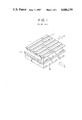
- FIG. 1 is a perspective view showing a prior-art laminated layer type fuel cell disclosed, for example, in Japanese Patent Application Laid-open No. 58-163181.
- numeral 1 designates a gas separation plate, in which rectilinear fuel channels 1a and oxidizer channels 1b of rectangular-shaped cross section are formed in perpendicular directions to one another on the upper and lower surfaces of the gas separation plate 1.
- Numeral 2 designates cells which are each formed of a fuel electrode, an electrolyte matrix and an oxidizer electrode mounted in operation between the two gas separation plates 1.
- a laminated layer type fuel cell includes the gas separation plates 1 and the cells 2 sequentially laminated one after another. Arrows A and B respectively designate the directions of flow of the fuel and the oxidizer.
- the fuel and the oxidizer supplied to the fuel channels 1a and the oxidizer channels 1b, respectively, are converted by the electrochemical reaction of the cells 2 into electric power.
- the current supplied by the cell reaction depends upon the partial pressures of the reaction components in the fuel and the oxidizer and increases as the partial pressures are higher.
- the current varies according to the cell reaction which depends upon the partial pressures of the fuel and the oxidizer reaction gases.
- the partial pressure of the reaction gases are high in the portions corresponding to the fuel and oxidizer inlets of the fuel channels 1a and the oxidizer channels 1b, the flowing current is large.
- the reaction gases are being consumed along the channels, at the upstream side of both channels, the partial pressures of the reaction gases decrease (i.e. especially in the portions corresponding to the fuel and oxidizer outlets of the fuel channels 1a and the oxidizers channels 1b), resulting in a small current. Accordingly, there arises problems that the electrochemical reaction in the cells become uneven with the result that the temperature distribution in the cells become irregular.
- This invention has been made in order to eliminate the disadvantages described above, and has for its object to provide a laminated layer type fuel cell which can improve the cell characteristics by equalizing the cell reactions and the temperature distribution in the cells.
- the laminated layer type fuel cell according to this invention comprises gas separation plates, each having rectilinear and zigzag portions of fuel and oxidizer channels sandwiched between cells formed of fuel electrodes, electrolyte matrices, and oxidizer electrodes so as to equalize the cell reactions in the cells.
- FIG. 1 is a perspective view showing a prior-art laminated layer type fuel cell
- FIG. 2 is a plan view showing the gas separation plate of an embodiment of a laminated layer type fuel cell according to the present invention.
- FIG. 3 is a plan view showing another example of a gas separation plate of the invention.
- FIG. 2 shows an embodiment of the present invention.
- numeral 1 designates a gas separation plate
- numeral 3 designates fuel and oxidizer, channels having rectilinear portions 4 and zigzag portions 5.
- Symbol C designates the direction of flowing reaction gas of fuel or oxidizer.
- the length ratio of the rectilinear portions 4 to the zigzag portions 5 is, for example, 1:1, and the zigzag portions 5 are alternatively disposed at the upstream and downstream sides for reaction gas.
- the reaction gases are consumed by the cell reaction while the reaction gases pass the zigzag portions 5, the partial pressures of the reaction gases produced by the electrochemical reaction are decreased and the reaction gases are exhausted through the rectilinear portions 4 rapidly from the outlet of the gas channels 3.
- the time that the reaction gases pass the rectilinear portions 4 is shorter than the time that the reaction gases pass the zigzag portions 5.
- the reaction gases are fed into the zigzag portions 5 in the state that the decrease in the partial pressures so of the reaction gases is less, and the reaction gas is consumed by the cell reaction while passing the zigzag portions 5. Therefore, since the cell reaction mainly occurs in the zigzag portions 5 of the fuel channels 3 of the reaction gases, the cell reaction can be uniformly performed in the cells by alternatively disposing the zigzag portions 5 at the upstream and downstream sides.
- the length ratio of the rectilinear portions 4 to the zigzag portions 5 of the fuel channels 3 is 1:1.
- this invention is not limited to this particular embodiment.
- the ratio of the lengths of the rectilinear portions 4 to the zigzag portion 5 may be 2:1 to 4:1 or any other arbitrary ratio.
- FIG. 3 is a plan view showing another embodiment of a laminated layer type fuel cell in which the length ratio of the rectilinear portions 4 to the zigzag portions 5 of the fuel channels 3 is 2:1 and the zigzag portions are sequentially displaced in every channel.
- the fuel channels 3 are advantageous to equalize the gas reaction in the cells in the same manner or higher than the previous embodiment.
- this invention is not limited to the particular embodiment.
- this invention may be applied to the fuel channels of the electrode substrate formed with reaction gas channels in at least one of the fuel electrode or oxidizer electrode of the electrode substrate, so-called ribbed electrode substrate.
- the configuration of the channels in this invention may be applied to one or both of the fuel side channel and the oxidizer side channel.
- the channels of the reaction gas are formed of the rectilinear portions and the zigzag portions and the cell reaction can be uniformly conducted within the cells. Therefore, the consumption of the reaction gas in the rectilinear portions is less along the rectilinear portion gas channels disposed at the upstream side, and higher reaction partial pressure can be supplied to the downstream side. Thus, the cell reaction may be effectively performed even at the downstream side. Consequently, the laminated layer type fuel cell in which the cell characteristics are improved and the temperature distribution is uniform can be provided.
Abstract
Description
Claims (3)
Applications Claiming Priority (2)
| Application Number | Priority Date | Filing Date | Title |
|---|---|---|---|
| JP60179632A JPS6240168A (en) | 1985-08-13 | 1985-08-13 | Stacked fuel cell |
| JP60-179632 | 1985-08-13 |
Publications (1)
| Publication Number | Publication Date |
|---|---|
| US4686159A true US4686159A (en) | 1987-08-11 |
Family
ID=16069157
Family Applications (1)
| Application Number | Title | Priority Date | Filing Date |
|---|---|---|---|
| US06/895,722 Expired - Lifetime US4686159A (en) | 1985-08-13 | 1986-08-12 | Laminated layer type fuel cell |
Country Status (2)
| Country | Link |
|---|---|
| US (1) | US4686159A (en) |
| JP (1) | JPS6240168A (en) |
Cited By (15)
| Publication number | Priority date | Publication date | Assignee | Title |
|---|---|---|---|---|
| US4973530A (en) * | 1989-12-21 | 1990-11-27 | The United States Of America As Represented By The United States Department Of Energy | Fuel cell water transport |
| US4975342A (en) * | 1986-07-24 | 1990-12-04 | Mitsubishi Denki Kabushiki Kaisha | Fuel cell |
| US4988583A (en) * | 1989-08-30 | 1991-01-29 | Her Majesty The Queen As Represented By The Minister Of National Defence Of Her Majesty's Canadian Government | Novel fuel cell fluid flow field plate |
| US5108849A (en) * | 1989-08-30 | 1992-04-28 | Her Majesty The Queen In Right Of Canada, As Represented By The Minister Of National Defence In Her Britannic Majesty's Government Of The United Kingdom Of Great Britain And Northern Ireland | Fuel cell fluid flow field plate |
| US5350642A (en) * | 1992-05-08 | 1994-09-27 | Osaka Gas Co., Ltd. | Solid-electrolyte fuel cell system |
| US5686199A (en) * | 1996-05-07 | 1997-11-11 | Alliedsignal Inc. | Flow field plate for use in a proton exchange membrane fuel cell |
| US5773160A (en) * | 1994-06-24 | 1998-06-30 | Ballard Power Systems Inc. | Electrochemical fuel cell stack with concurrent flow of coolant and oxidant streams and countercurrent flow of fuel and oxidant streams |
| US5824428A (en) * | 1994-10-27 | 1998-10-20 | Aisin Seiki Kabushiki Kaisha | Fuel cell |
| US5932366A (en) * | 1994-09-03 | 1999-08-03 | Forschungszentrum Julich Gmbh | Solid electrolyte high temperature fuel cell |
| EP1107339A2 (en) * | 1999-12-02 | 2001-06-13 | General Motors Corporation | Flow channels in current collecting plates of fuel cells |
| US6500579B1 (en) | 1999-08-19 | 2002-12-31 | Mitsubishi Denki Kabushiki Kaisha | Fuel cell structure |
| US20030059662A1 (en) * | 2001-09-17 | 2003-03-27 | 3M Innovative Properties Company | Flow field |
| US20040151970A1 (en) * | 2003-01-31 | 2004-08-05 | 3M Innovative Properties Company | Flow field |
| US20080199751A1 (en) * | 2007-02-20 | 2008-08-21 | Commonwealth Scientific And Industrial Research Organisation | Bipolar plate for an air breathing fuel cell stack |
| CN104091956A (en) * | 2014-07-21 | 2014-10-08 | 江苏超洁绿色能源科技有限公司 | Regional and high-power air cooling type proton exchange membrane fuel cell (PEMFC) electric pile bipolar plate with counter-flow channel |
Families Citing this family (2)
| Publication number | Priority date | Publication date | Assignee | Title |
|---|---|---|---|---|
| JP2007265939A (en) * | 2006-03-30 | 2007-10-11 | Ngk Insulators Ltd | Electrochemical device |
| JP6874725B2 (en) * | 2018-03-28 | 2021-05-19 | トヨタ自動車株式会社 | Fuel cell |
Citations (8)
| Publication number | Priority date | Publication date | Assignee | Title |
|---|---|---|---|---|
| US3573102A (en) * | 1966-11-07 | 1971-03-30 | United Aircraft Corp | Fuel cell gas manifold system |
| US3573104A (en) * | 1968-05-09 | 1971-03-30 | Gen Electric | Fuel cell unit with novel fluid confining and directing features |
| US3994748A (en) * | 1975-05-02 | 1976-11-30 | United Technologies Corporation | Method for feeding reactant gas to fuel cells in a stack and apparatus therefor |
| US4276355A (en) * | 1980-04-28 | 1981-06-30 | Westinghouse Electric Corp. | Fuel cell system configurations |
| US4292379A (en) * | 1980-04-28 | 1981-09-29 | Westinghouse Electric Corp. | Variable area fuel cell process channels |
| US4383009A (en) * | 1981-09-21 | 1983-05-10 | The United States Of America As Represented By The United States Department Of Energy | Low hydrostatic head electrolyte addition to fuel cell stacks |
| JPS58163181A (en) * | 1982-03-23 | 1983-09-27 | Mitsubishi Electric Corp | Layer-built fuel cell |
| US4407904A (en) * | 1981-02-20 | 1983-10-04 | Hitachi, Ltd. | Fuel cell |
Family Cites Families (1)
| Publication number | Priority date | Publication date | Assignee | Title |
|---|---|---|---|---|
| JPS58161270A (en) * | 1982-03-19 | 1983-09-24 | Mitsubishi Electric Corp | Stacked fuel cell |
-
1985
- 1985-08-13 JP JP60179632A patent/JPS6240168A/en active Granted
-
1986
- 1986-08-12 US US06/895,722 patent/US4686159A/en not_active Expired - Lifetime
Patent Citations (8)
| Publication number | Priority date | Publication date | Assignee | Title |
|---|---|---|---|---|
| US3573102A (en) * | 1966-11-07 | 1971-03-30 | United Aircraft Corp | Fuel cell gas manifold system |
| US3573104A (en) * | 1968-05-09 | 1971-03-30 | Gen Electric | Fuel cell unit with novel fluid confining and directing features |
| US3994748A (en) * | 1975-05-02 | 1976-11-30 | United Technologies Corporation | Method for feeding reactant gas to fuel cells in a stack and apparatus therefor |
| US4276355A (en) * | 1980-04-28 | 1981-06-30 | Westinghouse Electric Corp. | Fuel cell system configurations |
| US4292379A (en) * | 1980-04-28 | 1981-09-29 | Westinghouse Electric Corp. | Variable area fuel cell process channels |
| US4407904A (en) * | 1981-02-20 | 1983-10-04 | Hitachi, Ltd. | Fuel cell |
| US4383009A (en) * | 1981-09-21 | 1983-05-10 | The United States Of America As Represented By The United States Department Of Energy | Low hydrostatic head electrolyte addition to fuel cell stacks |
| JPS58163181A (en) * | 1982-03-23 | 1983-09-27 | Mitsubishi Electric Corp | Layer-built fuel cell |
Cited By (21)
| Publication number | Priority date | Publication date | Assignee | Title |
|---|---|---|---|---|
| US4975342A (en) * | 1986-07-24 | 1990-12-04 | Mitsubishi Denki Kabushiki Kaisha | Fuel cell |
| US4988583A (en) * | 1989-08-30 | 1991-01-29 | Her Majesty The Queen As Represented By The Minister Of National Defence Of Her Majesty's Canadian Government | Novel fuel cell fluid flow field plate |
| US5108849A (en) * | 1989-08-30 | 1992-04-28 | Her Majesty The Queen In Right Of Canada, As Represented By The Minister Of National Defence In Her Britannic Majesty's Government Of The United Kingdom Of Great Britain And Northern Ireland | Fuel cell fluid flow field plate |
| US4973530A (en) * | 1989-12-21 | 1990-11-27 | The United States Of America As Represented By The United States Department Of Energy | Fuel cell water transport |
| US5350642A (en) * | 1992-05-08 | 1994-09-27 | Osaka Gas Co., Ltd. | Solid-electrolyte fuel cell system |
| US5773160A (en) * | 1994-06-24 | 1998-06-30 | Ballard Power Systems Inc. | Electrochemical fuel cell stack with concurrent flow of coolant and oxidant streams and countercurrent flow of fuel and oxidant streams |
| US5932366A (en) * | 1994-09-03 | 1999-08-03 | Forschungszentrum Julich Gmbh | Solid electrolyte high temperature fuel cell |
| US5824428A (en) * | 1994-10-27 | 1998-10-20 | Aisin Seiki Kabushiki Kaisha | Fuel cell |
| US5686199A (en) * | 1996-05-07 | 1997-11-11 | Alliedsignal Inc. | Flow field plate for use in a proton exchange membrane fuel cell |
| US6500579B1 (en) | 1999-08-19 | 2002-12-31 | Mitsubishi Denki Kabushiki Kaisha | Fuel cell structure |
| US6358642B1 (en) | 1999-12-02 | 2002-03-19 | General Motors Corporation | Flow channels for fuel cell |
| EP1107339A2 (en) * | 1999-12-02 | 2001-06-13 | General Motors Corporation | Flow channels in current collecting plates of fuel cells |
| EP1107339A3 (en) * | 1999-12-02 | 2004-04-07 | General Motors Corporation | Flow channels in current collecting plates of fuel cells |
| US20030059662A1 (en) * | 2001-09-17 | 2003-03-27 | 3M Innovative Properties Company | Flow field |
| US6780536B2 (en) | 2001-09-17 | 2004-08-24 | 3M Innovative Properties Company | Flow field |
| US20040151970A1 (en) * | 2003-01-31 | 2004-08-05 | 3M Innovative Properties Company | Flow field |
| US7482088B2 (en) | 2003-01-31 | 2009-01-27 | 3M Innovative Properties Company | Flow field |
| US20090104506A1 (en) * | 2003-01-31 | 2009-04-23 | 3M Innovative Properties Company | Flow field |
| US8192856B2 (en) | 2003-01-31 | 2012-06-05 | 3M Innovative Properties Company | Flow field |
| US20080199751A1 (en) * | 2007-02-20 | 2008-08-21 | Commonwealth Scientific And Industrial Research Organisation | Bipolar plate for an air breathing fuel cell stack |
| CN104091956A (en) * | 2014-07-21 | 2014-10-08 | 江苏超洁绿色能源科技有限公司 | Regional and high-power air cooling type proton exchange membrane fuel cell (PEMFC) electric pile bipolar plate with counter-flow channel |
Also Published As
| Publication number | Publication date |
|---|---|
| JPH0437550B2 (en) | 1992-06-19 |
| JPS6240168A (en) | 1987-02-21 |
Similar Documents
| Publication | Publication Date | Title |
|---|---|---|
| US4686159A (en) | Laminated layer type fuel cell | |
| US4292379A (en) | Variable area fuel cell process channels | |
| US6593022B1 (en) | Membrane electrode assembly providing interconnection of reactant gas flowpaths in undulate layer fuel cell stacks | |
| JP4700910B2 (en) | Fuel cell flow field plate | |
| US20060210855A1 (en) | Flow field plate arrangement | |
| JP2000231929A (en) | Fuel cell | |
| JPH08222237A (en) | Separator for fuel cell | |
| CA2594530C (en) | Fuel cell separator | |
| CA2390573C (en) | Separator for a fuel cell | |
| JP4560992B2 (en) | Fuel cell manifold | |
| EP1627443B1 (en) | Improvements in fuel utilisation in electrochemical fuel cells | |
| US4769298A (en) | Laminated fuel cell | |
| US4074020A (en) | Cross-feed fuel cell battery with filter press type structure of polygonal cross-section | |
| US3484298A (en) | Electrode backing plate for electrochemical cells | |
| JP4507453B2 (en) | Fuel cell manifold | |
| JPS63248073A (en) | Stacked fuel cell | |
| JPS6039773A (en) | Layer-built fuel cell | |
| JPH0660901A (en) | Gas feeding structure for fuel cell | |
| JPS5830074A (en) | Fuel cell | |
| JPS618853A (en) | Layer-built fuel cell | |
| JP2517703B2 (en) | Fuel cell | |
| JPH0222934Y2 (en) | ||
| JPH0142935Y2 (en) | ||
| JP2002083613A (en) | Gas flow channel of fuel cell | |
| JPH0646571B2 (en) | Fuel cell |
Legal Events
| Date | Code | Title | Description |
|---|---|---|---|
| AS | Assignment |
Owner name: MITSUBISHI DENKI KABUSHIKI KAISHA, 2-3, MARUNOUCHI Free format text: ASSIGNMENT OF ASSIGNORS INTEREST.;ASSIGNOR:MIYOSHI, HIDEAKI;REEL/FRAME:004606/0260 Effective date: 19860630 Owner name: MITSUBISHI DENKI KABUSHIKI KAISHA, 2-3, MARUNOUCHI Free format text: ASSIGNMENT OF ASSIGNORS INTEREST;ASSIGNOR:MIYOSHI, HIDEAKI;REEL/FRAME:004606/0260 Effective date: 19860630 |
|
| STCF | Information on status: patent grant |
Free format text: PATENTED CASE |
|
| FEPP | Fee payment procedure |
Free format text: PAYOR NUMBER ASSIGNED (ORIGINAL EVENT CODE: ASPN); ENTITY STATUS OF PATENT OWNER: LARGE ENTITY |
|
| FPAY | Fee payment |
Year of fee payment: 4 |
|
| AS | Assignment |
Owner name: NEW ENERGY AND INDUSTRIAL TECHNOLOGY DEVELOPMENT O Free format text: ASSIGNMENT OF ASSIGNORS INTEREST.;ASSIGNOR:MITSUBISHI DENKI KABUSHIKI KAISHA, A JAPANESE CORP.;REEL/FRAME:005841/0220 Effective date: 19910614 |
|
| FEPP | Fee payment procedure |
Free format text: PAYOR NUMBER ASSIGNED (ORIGINAL EVENT CODE: ASPN); ENTITY STATUS OF PATENT OWNER: LARGE ENTITY Free format text: PAYER NUMBER DE-ASSIGNED (ORIGINAL EVENT CODE: RMPN); ENTITY STATUS OF PATENT OWNER: LARGE ENTITY |
|
| FPAY | Fee payment |
Year of fee payment: 8 |
|
| FPAY | Fee payment |
Year of fee payment: 12 |