US4691962A - Convertible wheelchair/litter - Google Patents
Convertible wheelchair/litter Download PDFInfo
- Publication number
- US4691962A US4691962A US06/886,008 US88600886A US4691962A US 4691962 A US4691962 A US 4691962A US 88600886 A US88600886 A US 88600886A US 4691962 A US4691962 A US 4691962A
- Authority
- US
- United States
- Prior art keywords
- litter
- wheelchair
- combination
- seat
- cushion
- Prior art date
- Legal status (The legal status is an assumption and is not a legal conclusion. Google has not performed a legal analysis and makes no representation as to the accuracy of the status listed.)
- Expired - Lifetime
Links
- 239000012530 fluid Substances 0.000 claims description 15
- 230000000694 effects Effects 0.000 claims description 6
- 238000012856 packing Methods 0.000 claims description 4
- 238000007789 sealing Methods 0.000 claims 1
- 238000004140 cleaning Methods 0.000 abstract description 6
- 230000008901 benefit Effects 0.000 description 10
- 230000007246 mechanism Effects 0.000 description 8
- 230000009471 action Effects 0.000 description 6
- 230000008859 change Effects 0.000 description 3
- 239000000463 material Substances 0.000 description 3
- 208000010125 myocardial infarction Diseases 0.000 description 2
- 239000002689 soil Substances 0.000 description 2
- 239000002699 waste material Substances 0.000 description 2
- 208000010392 Bone Fractures Diseases 0.000 description 1
- VYZAMTAEIAYCRO-UHFFFAOYSA-N Chromium Chemical compound [Cr] VYZAMTAEIAYCRO-UHFFFAOYSA-N 0.000 description 1
- 201000005569 Gout Diseases 0.000 description 1
- 206010021639 Incontinence Diseases 0.000 description 1
- 229910000831 Steel Inorganic materials 0.000 description 1
- 230000003749 cleanliness Effects 0.000 description 1
- 230000005484 gravity Effects 0.000 description 1
- 230000036541 health Effects 0.000 description 1
- 231100000206 health hazard Toxicity 0.000 description 1
- 239000002184 metal Substances 0.000 description 1
- 230000008707 rearrangement Effects 0.000 description 1
- 230000000284 resting effect Effects 0.000 description 1
- 229910001220 stainless steel Inorganic materials 0.000 description 1
- 239000010935 stainless steel Substances 0.000 description 1
- 239000010959 steel Substances 0.000 description 1
- 210000004916 vomit Anatomy 0.000 description 1
- 230000008673 vomiting Effects 0.000 description 1
- XLYOFNOQVPJJNP-UHFFFAOYSA-N water Substances O XLYOFNOQVPJJNP-UHFFFAOYSA-N 0.000 description 1
- 238000003466 welding Methods 0.000 description 1
Images


Classifications
-
- A—HUMAN NECESSITIES
- A61—MEDICAL OR VETERINARY SCIENCE; HYGIENE
- A61G—TRANSPORT, PERSONAL CONVEYANCES, OR ACCOMMODATION SPECIALLY ADAPTED FOR PATIENTS OR DISABLED PERSONS; OPERATING TABLES OR CHAIRS; CHAIRS FOR DENTISTRY; FUNERAL DEVICES
- A61G5/00—Chairs or personal conveyances specially adapted for patients or disabled persons, e.g. wheelchairs
- A61G5/006—Chairs or personal conveyances specially adapted for patients or disabled persons, e.g. wheelchairs convertible to stretchers or beds
-
- Y—GENERAL TAGGING OF NEW TECHNOLOGICAL DEVELOPMENTS; GENERAL TAGGING OF CROSS-SECTIONAL TECHNOLOGIES SPANNING OVER SEVERAL SECTIONS OF THE IPC; TECHNICAL SUBJECTS COVERED BY FORMER USPC CROSS-REFERENCE ART COLLECTIONS [XRACs] AND DIGESTS
- Y10—TECHNICAL SUBJECTS COVERED BY FORMER USPC
- Y10S—TECHNICAL SUBJECTS COVERED BY FORMER USPC CROSS-REFERENCE ART COLLECTIONS [XRACs] AND DIGESTS
- Y10S297/00—Chairs and seats
- Y10S297/04—Wheelchair
Definitions
- This invention relates to apparatus for use by geriatric, seriously ill, invalid, and the like persons, wherein there is a need for a single piece of apparatus in which the patient can sit, and upon which the patient can lie. Further, it is necessary that it be possible to move the patient about while in the apparatus. That is, the invention serves the function of both a hospital litter and a wheelchair.
- the present invention is a substantial step forward in this art in that it provides an improved convertible chair/litter of the character described which will permit several advantageous features in use.
- Another area has to do with permitting relatively rapid motion from the chair to litter for emergency purposes, while at the same time providing means to comfortably cushion the reverse motion from litter to chair so as to ease the work of the attendant while at the same time assuring that the apparatus will not rapidly go into the chair configuration as it naturally tends to do due to the weight of the patient.
- the structural arrangement is such that when in the litter configuration certain parts of the apparatus, primarily the seat, carrying the bulk of the weight of the patient are at a higher level than they are in the chair configuration. If these cushioning means were not provided, it is possible that an unduly rapid motion of the apparatus could result, which unduly rapid motion could result in severe upsetting of the patient, and even throwing of the patient out of the apparatus. Preventing this, in the prior art, required the operator to use his strength to hold back against the weight to gently move the patient.
- the cushioning arrangement of the invention thus saves effort by the operator or attendant, while assuring no such potentially dangerous operation in the motion into the chair configuration.
- this cushioning is such that the desired rapid emergency motion can be achieved, that is, motion from chair to litter configuration.
- the present invention provides improved means to permit this cleaning, while also providing other advantages as to hygiene, all as set forth below.
- the present invention provides a convertible wheelchair/litter of the character described which solves all of the above problems, and which provides yet further advantages over the prior art in general.
- each foot rest is provided with a rachet type adjusting arrangement based on a relatively fine screw thread.
- a pawl cooperates with this thread to permit a great range of different adjustments. That is, each turn of the screw thread on the rod cooperating with the pawl corresponds to a separate adjusted position.
- Each foot rest includes an over-center latch arrangement which is automatically switched into release when that foot rest is moved up into litter configuration. Thereafter, when the device is moved back to the chair position the foot rests will automatically go all the way down to the vertical, normal seating position since the rachet was automatically released in litter position.
- the invention in this area comprises a cylinder which may be pneumatic or hydraulic, and which includes a relief area on the piston rod, and a slidable piston mounted on the rod and spring loaded to one position with respect to the relief area.
- the arrangement of parts is such that in one position the spring loaded piston will block the relief slot on the piston rod, thus assuring the full dampening effect of the cylinder overall on the motion of the apparatus from the litter to the chair configuration.
- the present invention provides means to permit quick removal of the seat cushion and the back cushion from the apparatus.
- the remainder of the apparatus other than these two major upholstered portions is made of stainless steel, chrome plated steel, and other materials which can withstand water.
- the two major upholstered pieces are quickly and easily removed, permitting their separate cleaning away from the apparatus, and permitting cleaning of the remainder of the apparatus, the metal framework and other parts, by, if desired, simply hosing down tht major apparatus.
- the present invention provides a convertible chair/litter for the environments described above which is a substantial step forward in this art, solves several long standing problems in the prior art, provides many heretofore unknown advantages in this type of apparatus, and which is yet simply and reliable in operation, and strong, practical, durable, and highly suited to its use.
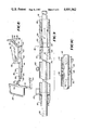
- FIG. 1 is a side elevational view with some parts broken away, some parts shown in dotted lines, and some parts omitted for the sake of clarity, showing a preferred embodiment of a convertible wheelchair/litter according to the invention
- FIGS. 2, 3 and 4 are a family of drawings showing the wheelchair/litter of FIG. 1 with additional parts removed, and showing the operation moving from the chair position of FIG. 1 to the litter position of FIG. 4;
- FIG. 5 is a detailed showing of the foot rests operating mechanism
- FIG. 6 is a cross-sectional view taken on line 6--6 of FIG. 5;
- FIG. 7 is a view similar to FIG. 5 showing the automatic unlocking action of the foot rests
- FIG. 8 is a perspective view of part of the chair of FIGS. 1-4 showing the cushioning cylinder, this view being taken looking downwardly from above the seat;
- FIG. 9 is a longitudinal cross-sectional view partly broken away of the cushioning cylinder.
- FIG. 10 is a view similar to part of FIG. 9 showing another position of the piston in the cushioning cylinder;
- FIG. 11 is an exploded view showing the manner of mounting the back rest of the device of FIG. 1;
- FIG. 12 is an exploded perspective view similar to FIG. 10 showing the mounting of the seat
- FIG. 13 is a view of a detail of FIG. 11.
- FIG. 14 is a view similar to FIG. 12 showing a variation of the seat mounting structure.
- FIG. 1 shows a convertible wheelchair/litter in accordance with the invention.
- the device is built about a framework 12 having wheels and means to mount all of the other portions, the framework itself not forming a material part of the present invention except as support for the various other parts described below.
- a pair of seat frame members 18 are pivoted at the rear ends to their bottom of the back rest framework 14 at pivot points 20, which can be in the form of cross bars, see FIG. 14.
- Left and right foot rests 22 are pivoted at their upper ends to their respective left and right seat frame members 18. The foot rests 22 are symmetrical but otherwise identical to each other.
- Means are provided to lift the foot rests 22 when moving from the chair configuration of FIG. 1 into the litter configuration of FIG. 4, and to thereafter permit the foot rests to return to the normal vertical unadjusted position when the chair is again moved back from the litter to the chair configuration.
- a foot rest lifting bar 26 which is connected to and operated by the guide cylinder and cushioning cylinder arrangement by means and in a manner described below. This bar 26 is caused to swing upwardly and to the left as shown in the drawings to progressively move both foot rests together up to the litter position. The action is depicted by the sequence of FIGS. 2, 3 and 4.
- Each assembly 28 includes an elongated adjusting screw 30, having an adjusting nut or stop member 32 at one end and a securing nut 34 at the opposite end which fixes that end of the adjusting screw 30 to a bracket 36 fixed to the underside of the seat 18.
- Means to guide each foot rest's motion on the individual screws 30 and to adjust the position of the foot rests with respect to the seat are provided. These means comprise a bracket 38 to which the other parts are mounted, including a guide sleeve 40 at the lower end of the bracket 38. This sleeve 40 as shown in FIG. 5 snugly but slidingly receives the adjusting screw 30.
- Bracket 40 carries a pawl 42 pivotedly mounted to the bracket at a pivot 44.
- Pawl 42 carries a manual operating lever 46 to permit the operator to change the position of the pawl.
- FIG. 5 shows arbitrary adjusted positions of the foot rests 22, for example, the position of the left hand foot rest in FIG. 1.
- FIG. 7 shows the position of the foot rests apparatus in the litter position of the invention device as shown in FIG. 4.
- Means are provided to hold the pawl 42 in either the adjusted position of FIG. 5 or the release position of FIG. 7, whichever position the pawl is in.
- These means comprise an over-center spring arrangement, the operation of which can be easily seen by reference to the imaginary line 45 shown in FIGS. 5 and 7.
- This over-center spring arrangement comprises an upper bracket 48 which is welded or otherwise secured to the side of the bracket 38.
- An over-center pin fits in a snug opening in the bracket 48 at one end, and has its other end pivoted as at 52 to the upper end of the pawl 42.
- a spring arrangement 54 is constrained between the bracket 48 and a stop shoulder 56 on the pin 50 to strongly urge the pawl to the over-center position to the right of line 45 in FIG. 5 or the other over-center position to the left of line 46 as shown in FIG. 7.
- the pawl tooth 58 at the lower end of the pawl 42 is defined by a cut-out 60.
- the foot rest structure as shown in FIGS. 5-7 and described above also has the advantage that it permits racheting from lower positions to higher adjusted positions. That is, imagining that the user has adjusted the right hand foot rest to the relatively low position shown in FIG. 1, and it should now be necessary or desirable to adjust that right hand leg rest to a higher position such as that shown by the left hand leg rest, the over-center to the right arrangement shown in FIG. 5 will permit such racheting, the spring 54 taking up the slight amount of motion of the pawl caused by the tooth 58 passing over each individual screw thread.
- the parts are configured so that the height of the thread is insufficient to throw over the over-center arrangement, the motion caused by going over the thread is merely absorbed by the spring.
- the height of the nut is sufficient to "kick" the over-center apparatus over to the left, as shown in FIG. 7.
- the leg rests can be set to an adjusted position using the manual handle 46, and higher adjusted positions can be automatically set by simply lifting the foot rests without having to further manually adjust.
- lower adjusted positions will require the operator to release the handle.
- the operator can take advantage of the racheting arrangement even in this situation, by simply lowering the foot rests to the bottom, re-engaging it at the bottom, and then racheting it up one or two or three threads at a time until the patient is comfortable.
- Another advantage is provided by the nut 32 which operates the pawl 42. By simply moving the nut along the threads, the parts are configured to the proper operation, and causing the foot rests to arrive at the proper horizontal litter position.
- the diameter of the pin 50 with respect to the opening in the bracket 48 is such as to create an imaginary point or line of pivot of the pin 50 in the bracket 48, and this line is perpendicular to and coincident with the line 45, the imaginary over-center line of the mechanism of the pin 50 and the pawl 42. That is, the center line of the pin 50 and the imaginary over-center line 45 are coincident at that point in the travel of the mechanism which corresponds to the "on center" position of the over-center device. In use, of course, the center line of the pin 50 will always be to the right as shown in FIG. 5 or else in the other unlocked position to the left as shown in FIG. 7 with respect to the imaginary center line 45.
- Means are provided to control the motion of the invention wheelchair/litter between the chair position of FIG. 1 and the litter position of FIG. 4, and to also control the operation of the foot rest lift bar 26 in the manner described above.
- an intermediate bar 62 is provided.
- the foot rest lift bar which is of "U" configuration has its ends joined as by welding to the center portion of this intermediate bar 62.
- a pair of extension bars 64 which extend upwardly from the intermediate bar 62 and which join to arm rest bars 66 at pivot points 68.
- the extension bar 64 carries a pivot link member 70 rigidly fixed thereto, the outer end of which is pivoted as at 72 to the top forward corner of the main framework 12.
- Each arm rest bar 66 carries a pair of vertical guide bars 76 which are guided by means not shown for vertical motion with respect to the main framework 12 in order to assure that the arm rests remain essentially horizontal during motion, as seen from the set of "action" drawings FIGS. 1-4. These elements 76 have been eliminated in FIGS. 2, 3 and 4 for clarity.
- the back rest frame 14 carries a pair of brackets 78 which are fitted to pivot points 16 at the upper rear corner of the main framework 12.
- the linkage also includes the arm rest bars 66 and seat bars 18 which make up the horizontal parts of the linkage. At their rear ends, these bars are pivoted at 74 and 20 respectively both to the back rest frame 14. At their front ends, the linkage includes the extension bar 64 pivoted at its upper end at 68 to the arm rest bar 66, and to its lower end to the intermediate bar 62. Intermediate bar 62 supports the front end of the seat bars 18, the bars 18 simply resting on bar 62.
- Means are provided to control the motion of this linkage between the litter and chair positions in a certain manner, and to also provide means to cushion the motion and help take up the weight when moving from the litter position of FIG. 4 down to the chair position of FIG. 1, while at the same time having no effect on the motion in the opposite direction from chair to litter so as to not unduly further burden the operator.
- an assembly 80 comprising a cushioning cylinder 82 and a guide cylinder 84.
- the guide cylinder 84 is made of a pair of nested tubes of square or rectangular cross section and are relatively heavy and durable as they include means to lock the mechanism in the various adjusted positions shown in FIGS. 2, 3 and 4, as well as to serve as part of the linkage to take up the weight of the patient and of the mechanism itself.
- the locking assembly 86 is shown in phantom lines as it does not form a material part of the present invention. It includes a control cable 88 which leads up to a trigger or release bar 90 pivoted to the upper end of the back rest frame 14 in a closely spaced convenient position to a push bar 92.
- an attendant can manipulate the invention device when in the chair configuration by handling the push bar 92, while at the same time his hands are conveniently located with respect to the trigger 90 to change the adjusted position of the invention wheelchair/litter.
- a bar 94 is rigidly attached to the two main side frames 12 and extends therebetween, perpendicular to the paper as seen in FIG. 1.
- Bar 94 carries a pair of relatively short bars 96 to which another pair of bars 98 are pivoted as at 100.
- the rear end of the housing portion 102 of the guide cylinder 84 is pivoted to the lower end of the bars 98 at pivots 104.
- the guide cylinder 84 also includes a moving portion 106 nested within the housing portion 102, and the outer free end of the moving portion 106 is pivoted as at 108 to a yoke 110 which is rigidly fixed by way of a bracket 112 to the intermediate bar 62.
- the moving part 106 simply slides within the housing part 102, no hydraulic or other working fluid being provided therebetween.
- the cushioning function is provided by the cushioning cylinder 82 which comprises a cylinder housing 114 and a guide rod 116.
- Packing means 118 are provided at both ends of the cylinder housing 114 to seal the working fluid therein.
- a fill tube 120 is provided to "top up" the oil or air used as the working fluid in the cushioning cylinder 82.
- the rod 116 is considerably longer than the housing 114; at the minimum, by an amount equal to the throw or travel of this cylinder in moving from the seat position of FIG. 1 to the litter position of FIG. 4.
- the cushioning cylinder 82 is functionally joined to the linkage by way of bracket 122 which joins the stationery housing 102 of the guide cylinder 84 to the stationery housing 114 of the cushioning cylinder 82.
- a bracket 124 is fixed as by an opening 126 to the forward end of the rod 116 and to the moving guide cylinder 106 of the guide cylinder assembly 84.
- a piston 128 is provided inside the housing 114 in closely spaced position to the housing and to the rod 116 for motion with respect to both elements 114 and 116.
- a spring 130 urges the piston 128 to the left against a stop pin 132.
- Another stop pin 134 constrains the spring 130 between the piston 128 and itself.
- the rod 116 is formed with a cut-out 136, and the piston 128 moves with respect to this cut-out 136 between the positions of FIGS. 9 and 10 and adjusted positions therebetween.
- FIG. 8 and the description herein describes the housing 114 of the cushioning cylinder 82 as being fixed while the rod is moved in conjunction with the motion of the linkage, the opposite arrangement of parts is also possible. That is, the rod end could be fixed to a non-moving part of the invention wheelchiar/litter, while the cylinder housing 114 could be arranged to be the moving part. Such a rearrangement of parts might be desirable in some other embodiments of the the present invention.
- the arrow on the rod 16 in FIG. 9 indicates motion to the right which corresponds to lowering from litter to chair. In this motion it is necessary to cushion the action of the linkage in order to gently lower the patient.
- the weight of the patient, together with the weight of the mechanism itself, when lowering to the chair position from the litter position absent the cushioning provided by the cylinder 82, is sufficient to upset the patient, to move him violently, and in fact to even literally throw the patient out of the mechanism.
- FIGS. 11, 12 and 13 the removeable upholstery feature of the present invention is shown. Many parts have been omitted from these drawings, especially from the linkage, for the sake of clarity, and since such parts are not necessary for understanding this feature.
- the back rest 138 itself includes a pair of pins 140 at the upper corners thereof and a pair of hanger brackets 142 at the lower end thereof.
- the back rest frame 14 carries a bar 144 over which the fingers 142 can be easily fit, the fitting motion being shown in FIG. 11.
- the frame 14 At its upper end, just below the upper-most corners and closely adjacent thereto, the frame 14 carries a pair of tabs 146 which cooperate with the pins 140, and can be locked therein as shown in FIG. 13 by cotter pins 148.
- FIG. 12 The manner in which the seat member 150 is mounted to the seat bars 118 of the framework is shown in FIG. 12. This view is upside down, i.e., one could imagine oneself as lying on the floor looking up to the operator mounting the seat into the framework.
- the seat carries a pin 140A which cooperates with a tab 146A on one of the seat bars 18, and the companion seat bar carries a pair of tabs 152 which fit into "U" shaped brackets 154.
- the pin 140A and brackets 154 are, of course, on the underside of the seat 150.
- slip covers such slip covers not being shown as they are per se well known, i.e., analogous to fitted bed sheets, the slip covers can have elastic edges that fit over and around the respective back rest 138 and seat 150.
- FIG. 14 there is shown another variation wherein the quick-release concept used for the back rest can be adapted for use with the seat cushion. Parts similar to or the same as those shown in earlier Figures and described above are indicated by the same reference numerals followed by "B".
- Seat frame members 18 are formed with holes 156 which receive pins 140B on the seat 150, and fingers 142B fit over pivot bar 20 (see also FIG. 2).
- Cotter pins 148 secure the asemblage. The operation is analogous to that described above for the back seat and as shown in FIG. 11.
- This removable upholstery feature of the invention is not limited to use on convertible equipment, but can be used on seating equipment in general, such as regular wheel chairs and geriatric chairs; and even outside the health care environment such as in aircraft and on other vehicles and on conventional furniture, for both business and home use.
- the cotter pins 148 constitute manual locking means to hold the cushions in place.
- the fingers 142 and the brackets 154 are functionally quick release holding means to hold the back rest and the seat cushion, respectively, in their respective places on the seating equipment.
- the remaining parts of the upholstery as shown in FIG. 1 on the arm rests and on the foot rests can be permanent or removeable, and, in any case, are easily cleaned, if needed, after the seat and back rest are removed using the invention's advantageous quick release features described above.
Abstract
Description
Claims (17)
Priority Applications (1)
| Application Number | Priority Date | Filing Date | Title |
|---|---|---|---|
| US06/886,008 US4691962A (en) | 1984-11-21 | 1986-07-16 | Convertible wheelchair/litter |
Applications Claiming Priority (2)
| Application Number | Priority Date | Filing Date | Title |
|---|---|---|---|
| US06/673,850 US4632450A (en) | 1984-11-21 | 1984-11-21 | Convertible wheelchair/litter |
| US06/886,008 US4691962A (en) | 1984-11-21 | 1986-07-16 | Convertible wheelchair/litter |
Related Parent Applications (1)
| Application Number | Title | Priority Date | Filing Date |
|---|---|---|---|
| US06/673,850 Division US4632450A (en) | 1984-11-21 | 1984-11-21 | Convertible wheelchair/litter |
Related Child Applications (1)
| Application Number | Title | Priority Date | Filing Date |
|---|---|---|---|
| US07/685,710 Continuation-In-Part US4795214A (en) | 1984-11-21 | 1987-08-17 | Convertible wheelchair/litter |
Publications (1)
| Publication Number | Publication Date |
|---|---|
| US4691962A true US4691962A (en) | 1987-09-08 |
Family
ID=27101033
Family Applications (1)
| Application Number | Title | Priority Date | Filing Date |
|---|---|---|---|
| US06/886,008 Expired - Lifetime US4691962A (en) | 1984-11-21 | 1986-07-16 | Convertible wheelchair/litter |
Country Status (1)
| Country | Link |
|---|---|
| US (1) | US4691962A (en) |
Cited By (36)
| Publication number | Priority date | Publication date | Assignee | Title |
|---|---|---|---|---|
| US4949408A (en) * | 1989-09-29 | 1990-08-21 | Trkla Theodore A | All purpose wheelchair |
| US4974905A (en) * | 1987-08-10 | 1990-12-04 | Davis John W | Chair bed |
| US5050899A (en) * | 1990-07-06 | 1991-09-24 | Stensby Harold F | Medical crash-chair and treatment table |
| US5121938A (en) * | 1991-03-04 | 1992-06-16 | Invacare Corporation | Slip covers for wheelchairs |
| US5195803A (en) * | 1989-06-21 | 1993-03-23 | Invacare Corporation | Reclining seat back assembly for a wheelchair |
| US5865457A (en) * | 1997-01-08 | 1999-02-02 | La-Z-Boy Incorporated | Wheeled health care chair |
| US5882083A (en) * | 1996-03-08 | 1999-03-16 | Robinson; Bonnie A. | Dialysis seating unit |
| US6154690A (en) * | 1999-10-08 | 2000-11-28 | Coleman; Raquel | Multi-feature automated wheelchair |
| US6224156B1 (en) | 1998-02-03 | 2001-05-01 | Sunrise Medical Hhg Inc. | Seat back recliner kit for wheelchair |
| US6296265B1 (en) | 1997-10-06 | 2001-10-02 | Sunrise Medical Hhg Inc. | Recliner wheelchair having adjustable pivot point |
| US6499163B1 (en) * | 2000-11-08 | 2002-12-31 | Harold Stensby | Apparatus convertible to a chair or treatment table |
| US6742206B1 (en) * | 2003-04-03 | 2004-06-01 | Tai-Kang Han | Nurse robot |
| US6792633B1 (en) * | 1999-10-12 | 2004-09-21 | Takano Co., Ltd. | Stretcher |
| US20050046129A1 (en) * | 2003-08-15 | 2005-03-03 | Antonishak Stephen J. | Constant center of gravity lift and tilt mechanisms for a wheelchair seat |
| US20050088024A1 (en) * | 2003-10-08 | 2005-04-28 | Rozaieski Michael J. | Reclining seat with movable back support |
| US7025421B1 (en) * | 2003-07-28 | 2006-04-11 | Fowler Richard L | Worker's recliner |
| US20060086202A1 (en) * | 2004-10-20 | 2006-04-27 | Barlow Richard T | Articulating leg rest for a wheelchair |
| US20060113746A1 (en) * | 2004-02-18 | 2006-06-01 | Bright D A | Reclining wheelchair |
| US20060220350A1 (en) * | 2005-03-31 | 2006-10-05 | Reef Rick R | Bariatric phase chair |
| US20080129099A1 (en) * | 2006-12-04 | 2008-06-05 | Cycling & Health Tech Industry R & D Center | Seat reclining mechanism for power wheelchair |
| US7661696B1 (en) * | 2006-11-29 | 2010-02-16 | Revolutionary Wheelchair, Inc. | Wheeled chair |
| US8157287B1 (en) | 2010-10-21 | 2012-04-17 | Cleveland Valerie N | Convertible wheelchair |
| US8453283B2 (en) | 2010-11-03 | 2013-06-04 | Hill-Rom Services, Inc. | Patient support apparatus with movable siderail assembly |
| US8544866B2 (en) | 2010-02-11 | 2013-10-01 | Snow Solutions, LLC | Convertible wheelchairs with movable carriages for transferring patients to/from the wheelchairs |
| US8621688B2 (en) | 2010-12-13 | 2014-01-07 | Hill-Rom Services, Inc. | Siderail assembly for patient support apparatus |
| US8677535B2 (en) | 2010-10-08 | 2014-03-25 | Hill-Rom Services, Inc. | Patient support apparatus with storable egress handles |
| US8713727B2 (en) | 2010-07-30 | 2014-05-06 | Hill-Rom Services, Inc. | Siderail assembly for patient support apparatus |
| US8745786B2 (en) | 2010-11-10 | 2014-06-10 | Hill-Rom Services, Inc. | Siderail assembly for patient support apparatus |
| US9510981B2 (en) | 2013-03-14 | 2016-12-06 | Stryker Corporation | Reconfigurable transport apparatus |
| US10154930B2 (en) | 2016-08-01 | 2018-12-18 | Stryker Corporation | EMS backboard |
| GB2588772A (en) * | 2019-11-05 | 2021-05-12 | Careflex Ltd | Chair with adjustable foot rest |
| US11020293B2 (en) | 2016-08-01 | 2021-06-01 | Stryker Corporation | Multi-function person handling equipment |
| US11052005B2 (en) | 2017-09-19 | 2021-07-06 | Stryker Corporation | Patient support apparatus with handles for patient ambulation |
| US11116680B2 (en) | 2017-09-19 | 2021-09-14 | Stryker Corporation | Patient support apparatus for controlling patient ingress and egress |
| US11147726B2 (en) | 2016-08-01 | 2021-10-19 | Stryker Corporation | Person support apparatus system |
| US11160705B2 (en) | 2017-10-20 | 2021-11-02 | Stryker Corporation | Adjustable patient support apparatus for assisted egress and ingress |
Citations (4)
| Publication number | Priority date | Publication date | Assignee | Title |
|---|---|---|---|---|
| US1657285A (en) * | 1926-01-05 | 1928-01-24 | Siskin Harry | Theater chair |
| US4032191A (en) * | 1973-02-13 | 1977-06-28 | Fetsch Joseph T | Two-position school bus seat |
| US4365840A (en) * | 1980-10-30 | 1982-12-28 | Coach & Car Equipment Corporation | Seat with back cushion attachment |
| US4564238A (en) * | 1983-10-03 | 1986-01-14 | Spectro Industries, Inc. | Leg-rests for modified wheel-chair |
-
1986
- 1986-07-16 US US06/886,008 patent/US4691962A/en not_active Expired - Lifetime
Patent Citations (4)
| Publication number | Priority date | Publication date | Assignee | Title |
|---|---|---|---|---|
| US1657285A (en) * | 1926-01-05 | 1928-01-24 | Siskin Harry | Theater chair |
| US4032191A (en) * | 1973-02-13 | 1977-06-28 | Fetsch Joseph T | Two-position school bus seat |
| US4365840A (en) * | 1980-10-30 | 1982-12-28 | Coach & Car Equipment Corporation | Seat with back cushion attachment |
| US4564238A (en) * | 1983-10-03 | 1986-01-14 | Spectro Industries, Inc. | Leg-rests for modified wheel-chair |
Cited By (53)
| Publication number | Priority date | Publication date | Assignee | Title |
|---|---|---|---|---|
| US4974905A (en) * | 1987-08-10 | 1990-12-04 | Davis John W | Chair bed |
| US5195803A (en) * | 1989-06-21 | 1993-03-23 | Invacare Corporation | Reclining seat back assembly for a wheelchair |
| US4949408A (en) * | 1989-09-29 | 1990-08-21 | Trkla Theodore A | All purpose wheelchair |
| US5050899A (en) * | 1990-07-06 | 1991-09-24 | Stensby Harold F | Medical crash-chair and treatment table |
| US5121938A (en) * | 1991-03-04 | 1992-06-16 | Invacare Corporation | Slip covers for wheelchairs |
| US5882083A (en) * | 1996-03-08 | 1999-03-16 | Robinson; Bonnie A. | Dialysis seating unit |
| US5865457A (en) * | 1997-01-08 | 1999-02-02 | La-Z-Boy Incorporated | Wheeled health care chair |
| US6296265B1 (en) | 1997-10-06 | 2001-10-02 | Sunrise Medical Hhg Inc. | Recliner wheelchair having adjustable pivot point |
| US6224156B1 (en) | 1998-02-03 | 2001-05-01 | Sunrise Medical Hhg Inc. | Seat back recliner kit for wheelchair |
| US6154690A (en) * | 1999-10-08 | 2000-11-28 | Coleman; Raquel | Multi-feature automated wheelchair |
| US6792633B1 (en) * | 1999-10-12 | 2004-09-21 | Takano Co., Ltd. | Stretcher |
| US7003830B2 (en) | 1999-10-12 | 2006-02-28 | Takano Co., Ltd. | Support structure for supporting a portion of a body |
| US20040205895A1 (en) * | 1999-10-12 | 2004-10-21 | Takano Co., Ltd. | Support structure for supporting a portion of a body |
| US6499163B1 (en) * | 2000-11-08 | 2002-12-31 | Harold Stensby | Apparatus convertible to a chair or treatment table |
| US6742206B1 (en) * | 2003-04-03 | 2004-06-01 | Tai-Kang Han | Nurse robot |
| US7025421B1 (en) * | 2003-07-28 | 2006-04-11 | Fowler Richard L | Worker's recliner |
| US20050046129A1 (en) * | 2003-08-15 | 2005-03-03 | Antonishak Stephen J. | Constant center of gravity lift and tilt mechanisms for a wheelchair seat |
| US20050088024A1 (en) * | 2003-10-08 | 2005-04-28 | Rozaieski Michael J. | Reclining seat with movable back support |
| US7296856B2 (en) | 2003-10-08 | 2007-11-20 | Pride Mobility Products Corporation | Reclining seat with movable back support |
| US20060113746A1 (en) * | 2004-02-18 | 2006-06-01 | Bright D A | Reclining wheelchair |
| US7306251B2 (en) * | 2004-02-18 | 2007-12-11 | Jlg, Llc | Reclining wheelchair |
| US20060086202A1 (en) * | 2004-10-20 | 2006-04-27 | Barlow Richard T | Articulating leg rest for a wheelchair |
| US7360841B2 (en) | 2004-10-20 | 2008-04-22 | Pride Mobility Products Corporation | Articulating leg rest for a wheelchair |
| US20060220350A1 (en) * | 2005-03-31 | 2006-10-05 | Reef Rick R | Bariatric phase chair |
| US7661696B1 (en) * | 2006-11-29 | 2010-02-16 | Revolutionary Wheelchair, Inc. | Wheeled chair |
| US7585019B2 (en) * | 2006-12-04 | 2009-09-08 | Cycling & Health Tech Industry R & D Center | Seat reclining mechanism for power wheelchair |
| US20080129099A1 (en) * | 2006-12-04 | 2008-06-05 | Cycling & Health Tech Industry R & D Center | Seat reclining mechanism for power wheelchair |
| US8544866B2 (en) | 2010-02-11 | 2013-10-01 | Snow Solutions, LLC | Convertible wheelchairs with movable carriages for transferring patients to/from the wheelchairs |
| US8713727B2 (en) | 2010-07-30 | 2014-05-06 | Hill-Rom Services, Inc. | Siderail assembly for patient support apparatus |
| US8677535B2 (en) | 2010-10-08 | 2014-03-25 | Hill-Rom Services, Inc. | Patient support apparatus with storable egress handles |
| US8157287B1 (en) | 2010-10-21 | 2012-04-17 | Cleveland Valerie N | Convertible wheelchair |
| US8453283B2 (en) | 2010-11-03 | 2013-06-04 | Hill-Rom Services, Inc. | Patient support apparatus with movable siderail assembly |
| US8732875B2 (en) | 2010-11-03 | 2014-05-27 | Hill-Rom Services, Inc. | Patient support apparatus with movable siderail assembly |
| US9756954B2 (en) | 2010-11-10 | 2017-09-12 | Hill-Rom Services, Inc. | Siderail assembly for patient support appartatus |
| US8745786B2 (en) | 2010-11-10 | 2014-06-10 | Hill-Rom Services, Inc. | Siderail assembly for patient support apparatus |
| US8621688B2 (en) | 2010-12-13 | 2014-01-07 | Hill-Rom Services, Inc. | Siderail assembly for patient support apparatus |
| US9173797B2 (en) | 2010-12-13 | 2015-11-03 | Hill-Rom Services, Inc. | Siderail assembly for patient support apparatus |
| US9925098B2 (en) | 2013-03-14 | 2018-03-27 | Stryker Corporation | Reconfigurable transport apparatus |
| US11071661B2 (en) | 2013-03-14 | 2021-07-27 | Stryker Corporation | Transport apparatus |
| US10406043B2 (en) | 2013-03-14 | 2019-09-10 | Stryker Corporation | Transport apparatus |
| US11737933B2 (en) | 2013-03-14 | 2023-08-29 | Stryker Corporation | Transport apparatus |
| US9510981B2 (en) | 2013-03-14 | 2016-12-06 | Stryker Corporation | Reconfigurable transport apparatus |
| US10154930B2 (en) | 2016-08-01 | 2018-12-18 | Stryker Corporation | EMS backboard |
| US11020293B2 (en) | 2016-08-01 | 2021-06-01 | Stryker Corporation | Multi-function person handling equipment |
| US11147726B2 (en) | 2016-08-01 | 2021-10-19 | Stryker Corporation | Person support apparatus system |
| US11052005B2 (en) | 2017-09-19 | 2021-07-06 | Stryker Corporation | Patient support apparatus with handles for patient ambulation |
| US11116680B2 (en) | 2017-09-19 | 2021-09-14 | Stryker Corporation | Patient support apparatus for controlling patient ingress and egress |
| US11723821B2 (en) | 2017-09-19 | 2023-08-15 | Stryker Corporation | Patient support apparatus for controlling patient ingress and egress |
| US11160705B2 (en) | 2017-10-20 | 2021-11-02 | Stryker Corporation | Adjustable patient support apparatus for assisted egress and ingress |
| US11806290B2 (en) | 2017-10-20 | 2023-11-07 | Stryker Corporation | Adjustable patient support apparatus for assisted egress and ingress |
| GB2589439A (en) * | 2019-11-05 | 2021-06-02 | Careflex Ltd | Chair with adjustable foot rest |
| GB2588772A (en) * | 2019-11-05 | 2021-05-12 | Careflex Ltd | Chair with adjustable foot rest |
| GB2589439B (en) * | 2019-11-05 | 2023-12-06 | Careflex Ltd | Chair with adjustable foot rest |
Similar Documents
| Publication | Publication Date | Title |
|---|---|---|
| US4632450A (en) | Convertible wheelchair/litter | |
| US4691962A (en) | Convertible wheelchair/litter | |
| US4795214A (en) | Convertible wheelchair/litter | |
| US5333887A (en) | Wheelchair/gurney | |
| CA2601470C (en) | A height adjustable wheelchair | |
| US6839926B2 (en) | Patient support apparatus having auto contour | |
| US4453732A (en) | Patient transport and care vehicle | |
| US9095483B2 (en) | Full perineal wash system with removable seat | |
| US5890765A (en) | Health care reclining chair | |
| GB2098935A (en) | Collapsible wheelchair for a disabled person | |
| US4125269A (en) | Recliner-rocker geriatric wheel chair | |
| US20030184042A1 (en) | Reclinable wheelchair | |
| AU2009319252A1 (en) | Bed, particularly hospital or nursing bed | |
| US3382000A (en) | Vertically adjustable armrests for wheelchairs | |
| CA2717608A1 (en) | Full perineal wash system with movable seat | |
| US7131154B2 (en) | Mobile transport device | |
| US5039165A (en) | Wheelchair toileting module and method | |
| GB2158350A (en) | Reclinable chair | |
| US20050029855A1 (en) | Dynamic seating system for personal mobility vehicle | |
| US8151380B2 (en) | Wheelchair with enhanced toilet accessibility | |
| US3095235A (en) | Hydraulically operated bed chair | |
| GB2125285A (en) | Invalid chair | |
| US20040049841A1 (en) | Commode chair | |
| GB2101884A (en) | An invalid chair | |
| CN219184593U (en) | Wheelchair for transporting human body |
Legal Events
| Date | Code | Title | Description |
|---|---|---|---|
| STCF | Information on status: patent grant |
Free format text: PATENTED CASE |
|
| FEPP | Fee payment procedure |
Free format text: PAYOR NUMBER ASSIGNED (ORIGINAL EVENT CODE: ASPN); ENTITY STATUS OF PATENT OWNER: SMALL ENTITY |
|
| FPAY | Fee payment |
Year of fee payment: 4 |
|
| FPAY | Fee payment |
Year of fee payment: 8 |
|
| FPAY | Fee payment |
Year of fee payment: 12 |
|
| AS | Assignment |
Owner name: COMMERCE COMMERCIAL LEASING, LLC, NEW JERSEY Free format text: SECURITY AGREEMENT;ASSIGNOR:CAMBRIDGE TECHNOLOGIES, INC.;REEL/FRAME:016105/0020 Effective date: 20050601 |
|
| AS | Assignment |
Owner name: FIFTH STREET MEZZANINE PARTNERS II, L.P., NEW YORK Free format text: SECURITY AGREEMENT;ASSIGNOR:CAMBRIDGE TECHNOLOGIES, INC.;REEL/FRAME:017957/0262 Effective date: 20060630 |
|
| AS | Assignment |
Owner name: COMMERCE BANK, N.A., PENNSYLVANIA Free format text: SECURITY AGREEMENT;ASSIGNOR:CAMBRIDGE TECHNOLOGIES, INC.;REEL/FRAME:019955/0344 Effective date: 20070926 |