US4697231A - Machine control system - Google Patents
Machine control system Download PDFInfo
- Publication number
- US4697231A US4697231A US06/747,661 US74766185A US4697231A US 4697231 A US4697231 A US 4697231A US 74766185 A US74766185 A US 74766185A US 4697231 A US4697231 A US 4697231A
- Authority
- US
- United States
- Prior art keywords
- screen
- code
- controller
- screen image
- control system
- Prior art date
- Legal status (The legal status is an assumption and is not a legal conclusion. Google has not performed a legal analysis and makes no representation as to the accuracy of the status listed.)
- Expired - Fee Related
Links
Images


Classifications
-
- G—PHYSICS
- G05—CONTROLLING; REGULATING
- G05B—CONTROL OR REGULATING SYSTEMS IN GENERAL; FUNCTIONAL ELEMENTS OF SUCH SYSTEMS; MONITORING OR TESTING ARRANGEMENTS FOR SUCH SYSTEMS OR ELEMENTS
- G05B19/00—Programme-control systems
- G05B19/02—Programme-control systems electric
- G05B19/04—Programme control other than numerical control, i.e. in sequence controllers or logic controllers
- G05B19/05—Programmable logic controllers, e.g. simulating logic interconnections of signals according to ladder diagrams or function charts
- G05B19/056—Programming the PLC
-
- G—PHYSICS
- G06—COMPUTING; CALCULATING OR COUNTING
- G06F—ELECTRIC DIGITAL DATA PROCESSING
- G06F3/00—Input arrangements for transferring data to be processed into a form capable of being handled by the computer; Output arrangements for transferring data from processing unit to output unit, e.g. interface arrangements
- G06F3/01—Input arrangements or combined input and output arrangements for interaction between user and computer
- G06F3/048—Interaction techniques based on graphical user interfaces [GUI]
- G06F3/0487—Interaction techniques based on graphical user interfaces [GUI] using specific features provided by the input device, e.g. functions controlled by the rotation of a mouse with dual sensing arrangements, or of the nature of the input device, e.g. tap gestures based on pressure sensed by a digitiser
- G06F3/0489—Interaction techniques based on graphical user interfaces [GUI] using specific features provided by the input device, e.g. functions controlled by the rotation of a mouse with dual sensing arrangements, or of the nature of the input device, e.g. tap gestures based on pressure sensed by a digitiser using dedicated keyboard keys or combinations thereof
-
- G—PHYSICS
- G05—CONTROLLING; REGULATING
- G05B—CONTROL OR REGULATING SYSTEMS IN GENERAL; FUNCTIONAL ELEMENTS OF SUCH SYSTEMS; MONITORING OR TESTING ARRANGEMENTS FOR SUCH SYSTEMS OR ELEMENTS
- G05B2219/00—Program-control systems
- G05B2219/10—Plc systems
- G05B2219/13—Plc programming
- G05B2219/13015—Semi automatic, manual automatic
-
- G—PHYSICS
- G05—CONTROLLING; REGULATING
- G05B—CONTROL OR REGULATING SYSTEMS IN GENERAL; FUNCTIONAL ELEMENTS OF SUCH SYSTEMS; MONITORING OR TESTING ARRANGEMENTS FOR SUCH SYSTEMS OR ELEMENTS
- G05B2219/00—Program-control systems
- G05B2219/10—Plc systems
- G05B2219/14—Plc safety
- G05B2219/14092—Display menu and its code, sense code, compare with registered code
-
- G—PHYSICS
- G05—CONTROLLING; REGULATING
- G05B—CONTROL OR REGULATING SYSTEMS IN GENERAL; FUNCTIONAL ELEMENTS OF SUCH SYSTEMS; MONITORING OR TESTING ARRANGEMENTS FOR SUCH SYSTEMS OR ELEMENTS
- G05B2219/00—Program-control systems
- G05B2219/10—Plc systems
- G05B2219/14—Plc safety
- G05B2219/14119—Inhibit remote control
-
- G—PHYSICS
- G05—CONTROLLING; REGULATING
- G05B—CONTROL OR REGULATING SYSTEMS IN GENERAL; FUNCTIONAL ELEMENTS OF SUCH SYSTEMS; MONITORING OR TESTING ARRANGEMENTS FOR SUCH SYSTEMS OR ELEMENTS
- G05B2219/00—Program-control systems
- G05B2219/10—Plc systems
- G05B2219/15—Plc structure of the system
- G05B2219/15041—Sense area of screen, compare if corresponds with correct area
Definitions
- means are provided for connecting the second output lines to the machine controlled by the machine control system such that the switches provide respective control signals for the machine when the mode control switch is in the second state, thereby bypassing the machine control system.
- means are also provided for disabling control of the machine by the control system when the mode control switch is in the second state.
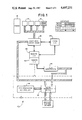
- FIG. 4 shows a block diagram of the presently preferred embodiment of the screen sensing system of this invention.
- This screen sensing system cooperates with the controllers 25, 26 and the CRT 52 and includes a sensing circuit 70 and a driving circuit 80.
- the controller 26 in cooperation with the CRT controller 25 generates a screen specific screen code on each of the screen images displayed on the CRT 52.
- the sensing circuit 70 senses the code displayed by the CRT 52, and supplies inputs indicative of the sensed code to the driving circuit 80.
- the driving circuit 80 switches 120 VAC signals in correspondence with the sensed code, and these signals are applied as inputs to the controllers 25,26.
- the controllers 25, 26 then compare the intended code with the sensed code to insure that the displayed screen on the CRT 52 is in fact the intended screen.
- FIG. 7 is a flow chart of a program executed by one of the controllers 25,26.
- each of the 32 separate screen images includes a respective binary screen image code between 0 and 31.
- the controller 26 commands any one of the 32 possible screen images, the corresponding screen image code is automatically displayed on the CRT 52.
- the sensing circuit 70 and the driving circuit 80 generate a 5 bit signal which is applied as an input to the controller and which defines the measured screen image code.
- FIG. 8 is a schematic diagram which illustrates a second safety feature of the machine control system 10.
- each of the pushbuttons 54 operates to switch a 120 VAC signal.
- a mode control switch 90 is provided which includes an array of parallel switches, each of which includes a common pole 92 connected to a respective one of the pushbuttons 54.
- first and second output lines 94, 96 from each of the individual switches are included in the mode control switch 90.
- the first output lines 94 are coupled to the controller 26 and the second output lines 96 are connected to the multi-axis drive communication unit 16 directly, bypassing the controller 26.
- each of the pushbuttons 54 supplies programming inputs to the controller 26.
- the first controller 26' powers the coil 102, the switch 106 is closed, and the switch 108 is open. Control signals from the manual pushbuttons are therefore routed to the first controller 26'. However, if either the first controller interrupts current to the coil 102 in response to a failure (such as a detected screen error as described above) or the operator opens the switch 104, then the switch 106 opens and the switch 108 closes. When this happens, control signals from the pushbuttons 54 are automatically routed to the second controller 26". Of course, in applications where a redundant controller 26" is not required, direct control or relay control over the controlled machine may be substituted for the second controller 26".
- the cabinet is mounted on cup mounts such as Part No. 52064 of Tech Products Corp., Dayton Ohio and the CRT 52 is mounted in the cabinet on vibration isolation mounts such as E-A-R Lab Mount L-020 supplied by Cabot Corporation, Indianapolis, Ind.
- a scratch resistant nonglare plastic is mounted on the inside surface of the front panel 50 to protect the glass face of the CRT 52.
- the rays 58 on the front panel 50 are colored white and yellow in alternation to correspond with the color of the associated pushbuttons 54 and the associated menu fields 62 in order to improve the visual alignment of each of the pushbuttons 54 with respect to the respective menu field 62.
Abstract
Description
              TABLE 1
______________________________________
SYMBOL    DESCRIPTION
______________________________________
TR        TRANSFORMER
          TRIAD TYPE F-138P 25.2VCT @ .06A
BR        FULL-WAVE BRIDGE RECTIFIER
          MOTOROLA NO. MDA920A4
CP        ELECTROLYTIC CAPACITOR
          SPRAGUE NO. TE1207 25MF 2500VDC
VR        VOLTAGE REGULATOR
          MOTOROLA NO. MC7818AC + 18V
P0-P4     PHOTORESISTOR
          VACTEC VT-741
R0-R4     POTENTIOMETER
          SPECTROL TYPE 64W lOKOHM 25 TURN
IC0-IC4   OPTO-ISOLATOR/DRIVER
          MOTOROLA NO. MOC3011
CS0-CS4   CERAMIC CAPACITOR
          CENTRALAB NO. DD-503 .05MF 500VDC
M0-M4     METAL OXIDE VARISTOR
          GENERAL ELECTRIC NO. V270MA2A
RS0-RS4   RESISTOR
          ALLEN-BRADLEY NO. EB4705
          470HM .5WATT 5%
T1        TERMINAL STRIP
          AUGAT TYPE 5MV-06
T2        TERMINAL STRIP
          AUGAT TYPE 5MV-13
______________________________________
Claims (14)
Priority Applications (1)
| Application Number | Priority Date | Filing Date | Title |
|---|---|---|---|
| US06/747,661 US4697231A (en) | 1985-06-21 | 1985-06-21 | Machine control system |
Applications Claiming Priority (1)
| Application Number | Priority Date | Filing Date | Title |
|---|---|---|---|
| US06/747,661 US4697231A (en) | 1985-06-21 | 1985-06-21 | Machine control system |
Publications (1)
| Publication Number | Publication Date |
|---|---|
| US4697231A true US4697231A (en) | 1987-09-29 |
Family
ID=25006096
Family Applications (1)
| Application Number | Title | Priority Date | Filing Date |
|---|---|---|---|
| US06/747,661 Expired - Fee Related US4697231A (en) | 1985-06-21 | 1985-06-21 | Machine control system |
Country Status (1)
| Country | Link |
|---|---|
| US (1) | US4697231A (en) |
Cited By (18)
| Publication number | Priority date | Publication date | Assignee | Title |
|---|---|---|---|---|
| US4811256A (en) * | 1986-11-14 | 1989-03-07 | Ishida Scales Manufacturing Company, Ltd. | Input-output method and device for combinational weighing system |
| US4821030A (en) * | 1986-12-19 | 1989-04-11 | Tektronix, Inc. | Touchscreen feedback system |
| US4843386A (en) * | 1986-05-12 | 1989-06-27 | Siemens Aktiengesellschaft | Remote control unit with hierarchical selection |
| US4912384A (en) * | 1987-10-07 | 1990-03-27 | Fanuc Ltd. | Emergency stop control circuit |
| US4921387A (en) * | 1988-09-16 | 1990-05-01 | The Budd Company | Combination transfer/turnover machine |
| FR2641878A1 (en) * | 1988-12-28 | 1990-07-20 | Nicolai Jean Pierre | System for monitoring and control of an automated process by visual display of synoptics on an intelligent graphics terminal |
| US4991077A (en) * | 1986-07-29 | 1991-02-05 | Fuji Electric Co., Ltd. | Programmable operator's console |
| EP0412308A2 (en) * | 1989-08-10 | 1991-02-13 | Prüftechnik Dieter Busch Ag | Electronic calculator with softkey function display |
| EP0416512A2 (en) * | 1989-09-04 | 1991-03-13 | Omron Corporation | A programmable monitor system and method |
| US5224861A (en) * | 1990-09-17 | 1993-07-06 | Hughes Aircraft Company | Training device onboard instruction station |
| US5450334A (en) * | 1993-11-01 | 1995-09-12 | Pulizzi Engineering, Inc. | One time programmable switched-output controller |
| US5508911A (en) * | 1994-06-30 | 1996-04-16 | Fawn Industries, Inc. | Electronic data entry and analysis system |
| US5598527A (en) * | 1992-11-12 | 1997-01-28 | Sextant Avionique | Compact and ergonomic communications terminal equipped with proximity detection surfaces |
| US5600311A (en) * | 1995-04-17 | 1997-02-04 | Rice-Kelly Research & Engineering, Inc. | Environmental control system with auxiliary control interface |
| US6212439B1 (en) * | 1997-05-12 | 2001-04-03 | Daewoo Telecom Ltd. | Three memory user programmable buttons |
| CN109311204A (en) * | 2016-04-14 | 2019-02-05 | 东洋机械金属株式会社 | Display operating device and molding machine |
| CN109311206A (en) * | 2016-04-14 | 2019-02-05 | 东洋机械金属株式会社 | Display operating device and molding machine |
| WO2019207470A3 (en) * | 2018-04-24 | 2020-05-28 | Eth Zurich | Automatic camera head and operation method |
Citations (8)
| Publication number | Priority date | Publication date | Assignee | Title |
|---|---|---|---|---|
| US4087166A (en) * | 1976-03-02 | 1978-05-02 | Terminal Data Corporation | Microfiche roll reproducer |
| US4174891A (en) * | 1976-11-15 | 1979-11-20 | Bell & Howell Company | Microfilm reader/printer |
| US4303973A (en) * | 1976-10-29 | 1981-12-01 | The Foxboro Company | Industrial process control system |
| US4379292A (en) * | 1978-02-22 | 1983-04-05 | Nissan Motor Company, Limited | Method and system for displaying colors utilizing tristimulus values |
| US4448503A (en) * | 1981-04-21 | 1984-05-15 | Information Retrieval Systems Corp. | Automatic high speed microfilm searching system |
| US4452518A (en) * | 1981-12-31 | 1984-06-05 | Bell & Howell Company | Slide projector control apparatus |
| US4514641A (en) * | 1981-11-09 | 1985-04-30 | Canon Kabushiki Kaisha | Apparatus for retrieving information |
| US4568161A (en) * | 1984-01-13 | 1986-02-04 | Bell & Howell Company | Computer controlled slide projector interface arrangement |
-
1985
- 1985-06-21 US US06/747,661 patent/US4697231A/en not_active Expired - Fee Related
Patent Citations (8)
| Publication number | Priority date | Publication date | Assignee | Title |
|---|---|---|---|---|
| US4087166A (en) * | 1976-03-02 | 1978-05-02 | Terminal Data Corporation | Microfiche roll reproducer |
| US4303973A (en) * | 1976-10-29 | 1981-12-01 | The Foxboro Company | Industrial process control system |
| US4174891A (en) * | 1976-11-15 | 1979-11-20 | Bell & Howell Company | Microfilm reader/printer |
| US4379292A (en) * | 1978-02-22 | 1983-04-05 | Nissan Motor Company, Limited | Method and system for displaying colors utilizing tristimulus values |
| US4448503A (en) * | 1981-04-21 | 1984-05-15 | Information Retrieval Systems Corp. | Automatic high speed microfilm searching system |
| US4514641A (en) * | 1981-11-09 | 1985-04-30 | Canon Kabushiki Kaisha | Apparatus for retrieving information |
| US4452518A (en) * | 1981-12-31 | 1984-06-05 | Bell & Howell Company | Slide projector control apparatus |
| US4568161A (en) * | 1984-01-13 | 1986-02-04 | Bell & Howell Company | Computer controlled slide projector interface arrangement |
Cited By (25)
| Publication number | Priority date | Publication date | Assignee | Title |
|---|---|---|---|---|
| US4843386A (en) * | 1986-05-12 | 1989-06-27 | Siemens Aktiengesellschaft | Remote control unit with hierarchical selection |
| US4991077A (en) * | 1986-07-29 | 1991-02-05 | Fuji Electric Co., Ltd. | Programmable operator's console |
| US4811256A (en) * | 1986-11-14 | 1989-03-07 | Ishida Scales Manufacturing Company, Ltd. | Input-output method and device for combinational weighing system |
| US4821030A (en) * | 1986-12-19 | 1989-04-11 | Tektronix, Inc. | Touchscreen feedback system |
| US4912384A (en) * | 1987-10-07 | 1990-03-27 | Fanuc Ltd. | Emergency stop control circuit |
| US4921387A (en) * | 1988-09-16 | 1990-05-01 | The Budd Company | Combination transfer/turnover machine |
| FR2641878A1 (en) * | 1988-12-28 | 1990-07-20 | Nicolai Jean Pierre | System for monitoring and control of an automated process by visual display of synoptics on an intelligent graphics terminal |
| EP0412308A3 (en) * | 1989-08-10 | 1991-11-13 | Prueftechnik Dieter Busch + Partner Gmbh & Co | Electronic calculator with softkey function display |
| EP0412308A2 (en) * | 1989-08-10 | 1991-02-13 | Prüftechnik Dieter Busch Ag | Electronic calculator with softkey function display |
| US5426730A (en) * | 1989-09-04 | 1995-06-20 | Omron Corporation | Method and apparatus for displaying sequential function chart elements |
| EP0416512A2 (en) * | 1989-09-04 | 1991-03-13 | Omron Corporation | A programmable monitor system and method |
| EP0416512A3 (en) * | 1989-09-04 | 1991-11-27 | Omron Corporation | A programmable monitor system and method |
| US5224861A (en) * | 1990-09-17 | 1993-07-06 | Hughes Aircraft Company | Training device onboard instruction station |
| US5598527A (en) * | 1992-11-12 | 1997-01-28 | Sextant Avionique | Compact and ergonomic communications terminal equipped with proximity detection surfaces |
| US5450334A (en) * | 1993-11-01 | 1995-09-12 | Pulizzi Engineering, Inc. | One time programmable switched-output controller |
| US5557512A (en) * | 1994-06-30 | 1996-09-17 | Fawn Industries, Inc. | Electronic data entry and analysis system |
| US5508911A (en) * | 1994-06-30 | 1996-04-16 | Fawn Industries, Inc. | Electronic data entry and analysis system |
| US5600311A (en) * | 1995-04-17 | 1997-02-04 | Rice-Kelly Research & Engineering, Inc. | Environmental control system with auxiliary control interface |
| US6212439B1 (en) * | 1997-05-12 | 2001-04-03 | Daewoo Telecom Ltd. | Three memory user programmable buttons |
| CN109311204A (en) * | 2016-04-14 | 2019-02-05 | 东洋机械金属株式会社 | Display operating device and molding machine |
| CN109311206A (en) * | 2016-04-14 | 2019-02-05 | 东洋机械金属株式会社 | Display operating device and molding machine |
| EP3476564A4 (en) * | 2016-04-14 | 2020-01-22 | Toyo Machinery & Metal Co., Ltd. | Display operation device and molding machine |
| EP3479990A4 (en) * | 2016-04-14 | 2020-01-22 | Toyo Machinery & Metal Co., Ltd. | Display operation device and molding machine |
| WO2019207470A3 (en) * | 2018-04-24 | 2020-05-28 | Eth Zurich | Automatic camera head and operation method |
| US11683589B2 (en) | 2018-04-24 | 2023-06-20 | Eth Zurich | Automatic camera head and operation method |
Similar Documents
| Publication | Publication Date | Title |
|---|---|---|
| US4697231A (en) | Machine control system | |
| US4916628A (en) | Microprocessor-based control/status monitoring arrangement | |
| US5186308A (en) | Electrical system for industrial conveyors | |
| US10366845B2 (en) | Monitored adaptable emergency off-switch | |
| US7598628B2 (en) | Automated bypass method and apparatus | |
| US4961028A (en) | Lighting equipment | |
| EP0774822A1 (en) | Apparatus and method for programming and reviewing a plurality of parameters of an electrical switching device | |
| US6392557B1 (en) | Programmable logic controller override output board | |
| US5676055A (en) | Control device for a printing machine | |
| US4143410A (en) | Electric power system control utilizing low level signals and miniature gage wiring | |
| CN210377412U (en) | Composite operation panel system | |
| US3480938A (en) | Annunciator system | |
| WO2001092978A1 (en) | A driving mechanism and a tap-changer comprising such a driving mechanism | |
| KR100450302B1 (en) | air conditioning plant compressor switchboard panel for ship | |
| US5708357A (en) | Power circuit for electronic controller | |
| JPH02301812A (en) | Programmable controller | |
| CN111211727A (en) | Multifunctional closed-loop motor driver, driving device thereof and automation equipment | |
| JPH07143626A (en) | Electric control board and controller unit used for this board | |
| KR0133952B1 (en) | Monitoring unit for power-driven movable rack system | |
| JP2545552B2 (en) | Highly integrated control board | |
| EP4345548A1 (en) | Safety i/o module with multi-channel high side switch | |
| CN112235914B (en) | Display control circuit with lamp for cabin switch plate | |
| CN219018691U (en) | Laser and power supply device thereof | |
| US4315250A (en) | Connection arrangement for selection and display system | |
| KR910004374Y1 (en) | Spindle unit alarm indication device |
Legal Events
| Date | Code | Title | Description |
|---|---|---|---|
| AS | Assignment |
Owner name: F. J. LITTELL MACHINE COMPANY CHICAGO, IL A CORP Free format text: ASSIGNMENT OF ASSIGNORS INTEREST.;ASSIGNORS:BOYTOR, SAMUEL G.;JURS, JEFFRY W.;REEL/FRAME:004421/0927 Effective date: 19850515 Owner name: F. J. LITTELL MACHINE COMPANY, A CORP OF IL, ILLIN Free format text: ASSIGNMENT OF ASSIGNORS INTEREST;ASSIGNORS:BOYTOR, SAMUEL G.;JURS, JEFFRY W.;REEL/FRAME:004421/0927 Effective date: 19850515 |
|
| CC | Certificate of correction | ||
| AS | Assignment |
Owner name: CONTINENTAL BANK N.A. AS AGENT Free format text: SECURITY INTEREST;ASSIGNOR:ALLIED PRODUCTS CORPORATION, A DE CORP.;REEL/FRAME:005270/0416 Effective date: 19891215 |
|
| AS | Assignment |
Owner name: ALLIED PRODUCTS CORPORATION, A CORP. OF DELAWARE Free format text: RELEASED BY SECURED PARTY;ASSIGNOR:CONTINENTAL BANK N.A.;REEL/FRAME:005635/0117 Effective date: 19900124 Owner name: CONTINENTAL BANK N.A., ILLINOIS Free format text: SECURITY INTEREST;ASSIGNOR:ALLIED PRODUCTS CORPORATION;REEL/FRAME:005748/0940 Effective date: 19900124 |
|
| FEPP | Fee payment procedure |
Free format text: PAYOR NUMBER ASSIGNED (ORIGINAL EVENT CODE: ASPN); ENTITY STATUS OF PATENT OWNER: LARGE ENTITY |
|
| FPAY | Fee payment |
Year of fee payment: 4 |
|
| AS | Assignment |
Owner name: VIL-USA, INC. A CORPORATION OF IL Free format text: SECURITY INTEREST;ASSIGNOR:ALLIED PRODUCTS CORPORATION, A CORPORATION OF DE;REEL/FRAME:005814/0326 Effective date: 19910822 |
|
| AS | Assignment |
Owner name: MARINE MIDLAND BANK, N.A., NEW YORK Free format text: SECURITY INTEREST;ASSIGNOR:VIL-USA, INC;REEL/FRAME:006284/0243 Effective date: 19920909 |
|
| AS | Assignment |
Owner name: ALLIED PRODUCTS CORPORATION, ILLINOIS Free format text: RELEASE OF SECURITY INTEREST;ASSIGNOR:CONTINENTAL BANK, N.A.;REEL/FRAME:007094/0014 Effective date: 19940621 |
|
| AS | Assignment |
Owner name: LLOYDS BANK PLC, ENGLAND Free format text: SECURITY INTEREST;ASSIGNOR:LITTELL INTERNATIONAL, INC. (FORMERLY KNOWN AS VIL-USA, INC.);REEL/FRAME:007194/0692 Effective date: 19940728 Owner name: VERSON INTERNATIONAL GROUP PLC, ENGLAND Free format text: SECURITY INTEREST;ASSIGNOR:LITTELL INTERNATIONAL, INC. (FORMERLY KNOWN AS VIL-USA, INC.);REEL/FRAME:007194/0692 Effective date: 19940728 |
|
| FPAY | Fee payment |
Year of fee payment: 8 |
|
| AS | Assignment |
Owner name: MARINE MIDLAND BANK, NEW YORK Free format text: CHANGE OF NAME;ASSIGNOR:VIL-USA, INC.;REEL/FRAME:007470/0634 Effective date: 19941227 |
|
| AS | Assignment |
Owner name: LITTELL INTERNATIONAL, INC., FORMERLY KNOWN AS VIL Free format text: RELEASE OF INTEREST;ASSIGNOR:MARINE MIDLAND BANK SUCCESSOR BY CONVERSION TO MARINE MIDLAND BANK, N.A.;REEL/FRAME:008194/0008 Effective date: 19961011 |
|
| REMI | Maintenance fee reminder mailed | ||
| LAPS | Lapse for failure to pay maintenance fees | ||
| FP | Lapsed due to failure to pay maintenance fee |
Effective date: 19990929 |
|
| AS | Assignment |
Owner name: LITTELL INTERNATIONAL, INC. (F/K/A VIL-USA, INC., Free format text: RELEASE AND ASSIGNMENT OF PATENTS AND KNOW-HOW;ASSIGNOR:ALLIED PRODUCTS CORPORATION;REEL/FRAME:012188/0710 Effective date: 19970716 |
|
| AS | Assignment |
Owner name: LITTELL ACQUISITION CORPORATION, ILLINOIS Free format text: ASSIGNMENT OF ASSIGNORS INTEREST;ASSIGNOR:LITTELL INTERNATIONAL, INC.;REEL/FRAME:012447/0088 Effective date: 20010925 Owner name: LITTELL INTERNATIONAL, INC., ILLINOIS Free format text: ASSIGNMENT OF ASSIGNORS INTEREST;ASSIGNOR:LITTELL ACQUISITION CORPORATION;REEL/FRAME:012447/0105 Effective date: 20010928 Owner name: LITELL INTERNATIONAL, INC., ILLINOIS Free format text: DEED OF RELEASE AND CONSENT;ASSIGNOR:LLOYDS TSB BANK PLC (FORMERLY KNOWN AS LLOYDS BANK PLC);REEL/FRAME:012447/0111 Effective date: 20010928 |
|
| STCH | Information on status: patent discontinuation |
Free format text: PATENT EXPIRED DUE TO NONPAYMENT OF MAINTENANCE FEES UNDER 37 CFR 1.362 |