US4701954A - Multipulse LPC speech processing arrangement - Google Patents
Multipulse LPC speech processing arrangement Download PDFInfo
- Publication number
- US4701954A US4701954A US06/590,228 US59022884A US4701954A US 4701954 A US4701954 A US 4701954A US 59022884 A US59022884 A US 59022884A US 4701954 A US4701954 A US 4701954A
- Authority
- US
- United States
- Prior art keywords
- signal
- time frame
- speech pattern
- pattern portion
- speech
- Prior art date
- Legal status (The legal status is an assumption and is not a legal conclusion. Google has not performed a legal analysis and makes no representation as to the accuracy of the status listed.)
- Expired - Lifetime
Links
Images


Classifications
-
- G—PHYSICS
- G10—MUSICAL INSTRUMENTS; ACOUSTICS
- G10L—SPEECH ANALYSIS OR SYNTHESIS; SPEECH RECOGNITION; SPEECH OR VOICE PROCESSING; SPEECH OR AUDIO CODING OR DECODING
- G10L19/00—Speech or audio signals analysis-synthesis techniques for redundancy reduction, e.g. in vocoders; Coding or decoding of speech or audio signals, using source filter models or psychoacoustic analysis
- G10L19/04—Speech or audio signals analysis-synthesis techniques for redundancy reduction, e.g. in vocoders; Coding or decoding of speech or audio signals, using source filter models or psychoacoustic analysis using predictive techniques
- G10L19/08—Determination or coding of the excitation function; Determination or coding of the long-term prediction parameters
- G10L19/10—Determination or coding of the excitation function; Determination or coding of the long-term prediction parameters the excitation function being a multipulse excitation
Definitions
- This invention relates to speech analysis and more particularly to linear prediction speech pattern analyzers.
- Linear predictive coding is used extensively in digital speech transmission, speech recognition and speech synthesis systems which must operate at low bit rates.
- the efficiency of LPC arrangements results from the encoding of the speech information rather than the speech signal itself.
- the speech information corresponds to the shape of the vocal tract and its excitation and as is well known in the art, its bandwidth is substantially less than the bandwidth of the speech signal.
- the LPC coding technique partitions a speech pattern into a sequence of time frame intervals 5 to 20 milliseconds in duration.
- the speech signal is quasi-stationary during such time intervals and may be characterized by a relatively simple vocal tract model specified by a small number of parameters. For each time frame, a set of linear predictive parameters are generated which are representative of the spectral content of the speech pattern.
- Such parameters may be applied to a linear filter which models the human vocal tract along with signals representative of the vocal tract excitation to reconstruct a replica of the speech pattern.
- a system illustrative of such an arrangement is described in U.S. Pat. No. 3,624,302 issued to B. S. Atal, Nov. 30, 1971, and assigned to the same assignee.
- Vocal tract excitation for LPC speech coding and speech synthesis systems may take the form of pitch period signals for voiced speech, noise signals for unvoiced speech and a voiced-unvoiced signal corresponding to the type of speech in each successive LPC frame. While this excitation signal arrangement is sufficient to produce a replica of a speech pattern at relatively low bit rates, the resulting replica has limited intelligibility. A significant improvement in speech quality is obtained by using a predictive residual excitation signal corresponding to the difference between the speech pattern of a frame and a speech pattern produced in response to the LPC parameters of the frame. The predictive residual, however, is noise-like since it corresponds to the unpredicted portion of the speech pattern. Consequently, a very high bit rate is needed for its representation.
- U.S. Pat. No. 3,631,520 issued to B. S. Atal, Dec. 28, 1971, and assigned to the same assignee discloses a speech coded system utilizing predictive residual excitation.
- the bit rate of the multipulse excitation signal may be selected to conform to prescribed transmission and storage requirements.
- intelligibility is improved, partially voiced intervals are accurately encoded and classification of voiced and unvoiced speech intervals is eliminated.
- a multipulse excitation signal having approximately eight pulses per pitch period provides adequate speech quality at a bit rate substantially below that of the corresponding predictive residual.
- Speech pattern pitch varies widely among individuals. More particularly, the pitch found in voices of children and adult females is generally much higher than the pitch for voices of adult males.
- the bit rate for multipulse excitation signals increases with voice pitch if high speech quality is to be maintained for all speakers.
- the bit rate in speech processing using multipulse excitation for adequate speech quality is a function of speaker pitch. It is an object of the invention to provide improved speech pattern coding with reduced excitation signal bit rate that is substantially independent of voice pitch.
- the foregoing object is achieved through removal of redundancy in the prescribed format multipulse excitation signal.
- a certain redundancy is found in all portions a speech pattern and is particularly evident in voiced portions of the speech pattern.
- signals indicative of excitation signal redundancy over several frames of speech may be coded and utilized to form a lower bit rate (redundancy reduced) excitation signal from the coded excitation signal.
- the redundancy indicative signals are combined with the redundancy reduced coded excitation signal to provide the appropriate excitation.
- the transmission facility bit rate and the coded speech storage requirements may be substantially reduced.
- the invention is directed to a predictive speech pattern coding arrangement in which a speech pattern is sampled and the samples are partitioned into successive time frames. For each frame, a set of speech parameter signals are generated responsive to the frame sample signals and a signal representative of differences between the frame speech pattern and the speech parameter signal representative pattern is produced responsive to said frame predictive parameter signals and said frame speech pattern sample signals. A first signal is formed responsive to said frame speech parameter signals and said frame differences signal. A secnd signal is generated responsive to said frame speech parameter signals, and a third signal is produced that is representative of the similarities between the speech pattern of the frame and the speech pattern of preceding frames. Jointly responsive to the first, second and third signals, a prescribed format signal corresponding to the frame differences signal is formed. The second signal is modified responsive to said prescribed format signal.
- the speech parameter signals are predictive parameter signals and the frame differences signal is a predictive residual signal.
- At least one signal corresponding to the frame to frame similarities is formed for each frame and a replica of the frame speech pattern is generated responsive to the prescribed format signal, the frame to frame similarity signals and the prediction parameter signals of the frame.
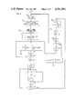
- FIG. 1 depicts a block diagram of a speech coding arrangement illustrative of the invention
- FIG. 2 depicts a block diagram of processing circuit arrangement that may be used in the arrangement of FIG. 1.
- FIGS. 3 and 4 show flow charts that illustrate the operation of the processing circuit of FIG. 2;
- FIG. 5 shows a speech pattern synthesis arrangement that may be utilized as a decoder for the arrangement of FIG. 1;
- FIG. 6 shows waveforms illustrating the speech processing according to the invention.
- FIG. 1 depicts a general block diagram of a speech processor that illustrates the invention.
- a speech pattern such as a spoken message is received by microphone transducer 101.
- the corresponding analog speech signal therefrom is band-limited and converted into a sequence of pulse samples in filter and sampler circuit 113 of prediction analyzer 110.
- the filtering may be arranged to remove frequency components of the speech signal above 4.0 KHz and the sampling may be at an 8.0 KHz rate as is well known in the art.
- the timing of the samples is controlled by sample clock SC from clock generator 103.
- Each sample from circuit 113 is transformed into an amplitude representative digital code in analog-to-digital converter 115.
- the speech samples from A/D converter 115 are delayed in delay 117 to allow time for the formation of speech parameter signals a k .
- the delayed samples are supplied to the input of prediction residual generator 118.
- the prediction residual generator is responsive to the delayed speech samples and the prediction parameters a k to form a signal corresponding to the differences therebetween.
- the formation of the predictive parameters and the prediction residual signal for each frame shown in predictive analyzer 110 may be performed according to the arrangement disclosed in U.S. Pat. No. 3,740,476 issued to B. S. Atal June 19, 1973, and assigned to the same assignee or in other arrangements well known in the art.
- Waveform 601 of FIG. 6 illustrates a typical speech pattern over a plurality of frames.
- Waveform 605 shows the prescribed format multipulse excitation signal for the speech pattern of waveform 601 in accordance with the arrangements described in the aforrementioned patent application and article. As a result of the invention, the similarities between the excitation signal of the current frame and the excitation signals of preceding frames are removed from the prescribed format multipulse signal of waveform 605.
- the pitch dependence of the multipulse signal is eliminated and the amplitude range of the multipulse signal is substantially reduced.
- the redundancy reduced multipulse signal of waveform 610 is obtained.
- a comparison between waveforms 605 and 610 illustrates the improvement that is achieved.
- Waveform 615 shows a replica of the pattern of waveform 601 obtained using the excitation signal of waveform 610, the redundancy parameter signals and the predictive parameter signals.
- the prediction residual signal d k and the predictive parameter signals a k for each successive frame are applied from circuit 110 to excitation signal forming circuit 120 at the beginning of the succeeding frame.
- Circuit 120 is operative to produce a redundancy reduced multielement excitation code EC having a predetermined number of bit positions for each frame and a redundancy parameter code ⁇ ,M* for the frame.
- Each excitation code corresponds to a sequence of 1 ⁇ i ⁇ I pulses representative of the excitation function of the frame with multiframe redundancy removed to make it pitch insensitive.
- the amplitude ⁇ i and location m i of each pulse within the frame is determined in the excitation signal forming circuit as well as the ⁇ and M* redundancy parameter signals so as to permit construction of a replica of the frame speech signal from the excitation signal when combined with the redundancy parameter signals, and the predictive parameter signals of the frame.
- the ⁇ i and m i signals are encoded in coder 131.
- the ⁇ and M signals are encoded in coder 155.
- the predictive residual signal d k and the predictive parameter signals a k of a frame are supplied to filter 121 via gates 122 and 124, respectively.
- frame clock signal FC opens gates 122 and 124 whereby the frame d k signal is applied to filter 121 and the frame a k signals are applied to filters 121 and 123.
- Filter 121 is adapted to modify signal d k so that the quantizing spectrum of the error signal is concentrated in the formant regions thereof.
- this filter arrangement is effective to mask the error in the high signal energy portions of the spectrum.
- Predictive filter 123 receives the frame predictive parameter signals a k from computer 119 and an excitation signal v(n) corresponding to the prescribed format multipulse excitation signal EC from excitation signal former 145.
- Filter 123 has the transfer function of Equation 1.
- Filter 121 forms a weighted frame speech signal y responsive to the predictive residual d k while filter 123 generates a weighted predictive speech signal y responsive to the multipulse excitation signal being formed over the frame interval in multipulse signal generator 127.
- the output of filter 121 is ##EQU4## where d k is the predictive residual signal from residual signal generator 118 and h n-k corresponds to the response of filter 121.
- the output of filter 123 is ##EQU5##
- Signals y(n) and y(n) are applied to frame correlation signal generator 125 and the current frame predictive parameters a k are applied to multiframe correlation signal generator 140.
- Multiframe correlation signal generator 140 is operative to form a multiframe correlation component signal y p (n) corresponding to the correlation of the speech pattern of the current frame to preceding frames, a signal z(n) corresponding to the contribution of preceding excitation of the current frame speech pattern, a current frame correlation parameter signal ⁇ , and a current frame correlation location signal M*.
- Signal z(n) is formed from its past values responsive to linear prediction parameter signals a k in accordance with ##EQU6## A range of samples M min to M max extending over a plurality of preceding frames is defined.
- a signal ##EQU7## representing the excitation of the preceding frame is produced from the proceeding frame prescribed format multipulse signal is produced.
- a signal ##EQU8## is formed corresponding to the contribution of the frame of excitation from m samples earlier.
- a signal ##EQU9## corresponding to the difference between the current value of the speech pattern y(n) and the sum of the past excitation contribution to the present speech pattern value z(n) and the contribution of the correlated component from sample ⁇ y p (n)(M)z(n,M) may be formed.
- Equation 7 may be expressed as ##EQU10##
- ⁇ can then be formed from equation 9 using the value of M* corresponding to the selected minimum signal E( ⁇ ,M) as per Equation 10.
- Signal y p (n) is supplied to frame correlation signal generator 125 which is operative to generate signal ##EQU13## where ##EQU14## responsive to signals y(n) from predictive filter 121, signal y(n) from predictive filter 123 and signal y p (n) from multiframe correlation signal generator 140.
- Signal C iq is representative of the weighted differences between signals y(n) and the combination of signals y(n) and y p (n).
- the effect of signal y p (n) in processor 125 is to remove long term redundancy from the weighted differences. The long term redundancy is generally related to the pitch predictable component of the speech pattern.
- the output of frame correlation generator 125 represents the maximum value of C iq over the current frame and its location q*.
- the signals ⁇ i and m i are formed iteratively until I such pulses are generated by feedback of the pulses through excitation signal former 145.
- the output of processor 125 has reduced redundancy so that the resulting excitation code obtained from multipulse signal generator 127 has a smaller dynamic range.
- the smaller dynamic range is illustrated by comparing waveforms 605 and 610 in FIG. 6. Additionally, the removal of the pitch related component from the multipulse excitation code renders the excitation substantially independent of the pitch of the input speech pattern. Consequently, a significant reduction in excitation code bit rate is achieved.
- Signal EC comprising the multipulse sequence ⁇ i , m i is applied to multiplexor 135 via coder 131.
- the multipulse signal EC is also supplied to excitation signal former 145 in which an excitation signal v(n) corresponding to signal EC is produced.
- Signal v(n) modifies the signal formed in predictive filter 123 to adjust the excitation signal EC so that the differences between the weighted speech representative signal from filter 121 and the weighted artificial speech representative signal from filter 123 are reduced.
- Multipulse signal generator 127 receives the C iq signals from frame correlation signal generator 127, selected the C iq signal having the maximum absolute vaue and i th element of the coded signal as per Equation 14.
- the index i is incremented to i+1 and signal y(n) at the output of predictive filter 123 is modified.
- the process in accordance with Equations 4, 5 and 6 is repeated to form element ⁇ i+1 , m i+1 .
- the signal having elements ⁇ i m 1' ⁇ 2 m 2 , . . . , ⁇ I m I is transferred to coder 131.
- coder 131 is operative to quantize the ⁇ i m i elements and to form a coded signal suitable for transmission to utilization device 148.
- Each of filters 121 and 123 in FIG. 1 may comprise a recursive filter of the type described in aforementioned U.S. Pat. No. 4,133,976.
- Each of generators 125, 127, and 140 as well as excitation signal former 145 may comprise one of the processor arrangements well known in the art adapted to perform the processing required by Equations 4 and 6 such as the C.S.P., Inc. Macro Arithmetic Processor System 100 or other processor arrangements well known in the art. Alternatively, the aforementioned C.S.P. system may be used to accomplish the processing required in all of these generating and forming units.
- Generator 140 includes a read only memory that permanently stores a set of instructions to perform the functions of Equations 9-11.
- Processor 125 includes a read-only memory which permanently stores programmed instructions to control the C iq signal formation in accordance with Equation 4.
- processor 127 includes a read-only memory which permanently stores programmed instructions to select the ⁇ i , m i signal elements according to Equation 6 as is well known in the art. These read only memories may be selectively connected to a single processor arrangement of the type described as shown in FIG. 2.
- the program instructions for the signal processing in the circuit of FIG. 1 is set forth in FORTRAN language form in Appendix A hereto.
- FIG. 3 depicts a flow chart showing the operations of signal generators 125, 127, 140, and 145 for each time frame.
- the h k impulse response signals are generated in box 305 responsive to the frame predictive parameters a k in accordance with the transfer function of Equation 1. This occurs after receipt of the FC signal from clock 103 in FIG. 1 as per wait box 303.
- the generation of the multiframe correlation signal y p (n) and the multiframe correlation parameter signals ⁇ and M* is then performed in multiframe signal generator 140 as per box 306.
- the operations of box 306 are shown in greater detail in the flow chart of FIG. 4.
- signal z(n) representative of the contribution of preceding excitation is generated (box 401) and stored in multiframe correlation signal generator 140 according to equation 1 responsive to the predictive parameter signals a k .
- Index M is set to Mmin and minimum error signal E* is set to zero in box 405.
- the contribution of the preceding M samples to the excitation is generated as per Equation 6a and 6b.
- Signals ⁇ , M*, and y p (n) are stored in generator 440.
- the element index i and the excitation pulse location index q are initially set to 1 in box 307.
- signal C iq is formed as per box 309.
- the location index q is incremented in box 311 and the formation of formation of the next location C iq signal is initiated.
- processor 127 is activated.
- the q index in processor 127 is initially set to 1 in box 315 and the i index as well as the C iq signals formed in processor 125 are transferred to processor 127.
- Signal C iq * which represents the C iq signal having the maximum absolute value and its location q* are set to zero in box 317.
- the absolute values of the C iq signals are compared to signal C iq * and the maximum of these absolute values is stored as signal C iq * in the loop including boxes 319, 321, 323, and 325.
- box 327 is entered from box 325.
- the excitation code element location m i is set to q* and the magnitude of the excitation code element ⁇ i is generated in accordance with Equation 6.
- the ⁇ i m i element is output to predictive filter 123 as per box 328 and index is incremented as per box 329.
- signal v(n) for the frame is generated as per Equation 6a (box 340) and wait box 303 is reentered. Processors 125 and 127 are then placed in wait states until the FC frame clock pulse of the next frame.
- the excitation code in processor 127 is also supplied to code 131.
- the coder is operative to transform the excitation code from processor 127 into a form suitable for use in network 140.
- the prediction parameter signals a k for the frame are supplied to an input of multiplexer 135 via delay 133 as signals a' k .
- the excitation coded signal ECS from coder 131 is applied to the other input of the multiplexer.
- the multiplexed excitation and predictive parameter codes for the frame are then sent to utilization device 148.
- the data processing circuit depicted in FIG. 2 provides an alternative arrangement to excitation signal forming circuit 120 of FIG. 1.
- the circuit of FIG. 2 yields the excitation code ⁇ i , m i for each frame of the speech pattern as well as the redundancy parameter signals for the frame ⁇ , M* in response to the frame prediction residual signal d k and the frame prediction parameter signals a k in
- the circuit of FIG. 2 may comprise the previously mentioned C.S.P., Inc. Macro Arithmetic Processor System 100 or other processor arrangements well known in the art.
- processor 210 receives the predictive parameter signals a k and the prediction residual signals d k of each successive frame of the speech pattern from circuit 110 via store 218.
- the processor is operative to form the excitation code signal elements ⁇ 1 m 1 , ⁇ 2 , m 2 , . . . , ⁇ I , m I , and redundancy parameter signals ⁇ and M* under control of permanently stored instructions in predictive filter processing subroutine read-only memory 201, multiframe correlation processing read-only memory 212, frame correlation signal processing read-only memory 217, and excitation processing read-only memory 205.
- the permanently stored instructions of these read-only memories are set forth in Appendix A.
- Processor 210 comprises common bus 225, data memory 230, central processor 240, arithmetic processor 250, controller interface 220 and input-output interface 260.
- central processor 240 is adapted to control the sequence of operations of the other units of processor 210 responsive to coded instructions from controller 215.
- Arithmetic processor 250 is adapted to perform the arithmetic processing on coded signals from data memory 230 responsive to control signals from central processor 240.
- Data memory 230 stores signals as directed by central processor 240 and provides such signals to arithmetic processor 250 and input-output interface 260.
- Controller interface 220 provides a communication link for the program instructions in the read-only memories 201, 205, 212, and 217 to central processor 240 via controller 215, and input-output interface 260 permits the d k and a k signal to be supplied to data memory 230 and supplies output signals ⁇ i , m i , ⁇ and M* from the data memory to coders 131 and 155 in FIG. 1.
- FIG. 2 The operation of the circuit of FIG. 2 is illustrated in the flow charts of FIGS. 3 and 4.
- box 305 in FIG. 3 is entered via box 303 after signal ST is obtained from clock signal generator 103 in FIG. 1.
- the predictive filter impulse response for signals y(n) and y(n) are formed as per box 305 in processors 240 and 250 under control of instructions from predictive filter processing ROM 201.
- Box 306 is then entered and the operations of the flow chart of FIG. 4 are carried out responsive to the instructions stored in ROM 212.
- These operations result in the formation of signals y p (n), ⁇ , and M* and have been described with respect to FIG. 1.
- Signals ⁇ and M* are made available at the output of input-output interface 260 and signal y p (n) is stored in data memory 230.
- Controller 215 Upon completion of the operations of box 306, Controller 215 connects frame correlation signal processing ROM 217 to central processor 240 via controller interface 220 and bus 225 so that the signals C iq , C iq *, and q* are formed as per the operations of boxes 307 through 325 for the current value of excitation signal index i.
- Excitation signal processing ROM 205 is then connected to computer 210 by controller 215 and the signals ⁇ i and m i are generated in boxes 327 through 333 as previously described with respect to FIG. 1.
- Signal v(n) is then produced for use in the next frame in box 340 as per equation 6a.
- controller 215 Upon completion of the operations of FIG. 3 for excitation signal ⁇ I , m I , controller 215 places the circuit of FIG. 2 in a wait state as per box 303.
- the frame excitation code and the frame redundancy parameter signals from the processor of FIG. 2 are supplied via input-output interface 260 to coders 131 and 155 in FIG. 1 as is well known in the art. Coders 131 and 155 are operative as previously mentioned to quantize and format the excitation code and the redundancy parameter signals for application to utilization device 148.
- the a k prediction parameter signals of the frame are applied to one input of multiplexer 135 through delay 133 so that the frame excitation code from coder 131 may be appropriately multiplexed therewith.
- Utilization device 148 may be a communication system, the message store of a voice storage arrangement, or apparatus adapted to store a complete message or vocabulary of prescribed message units, e.g., words, phonemes, etc., for use in speech synthesizers. Wheatever the message unit, the resulting sequence of frame codes from circuit 120 are forwarded via utilization device 148 to a speech synthesizer such as that shown in FIG. 5. The synthesizer, in turn, utilizes the frame excitation and redundance parameter signal codes from circuit 120 as well as the frame predictive parameter codes to construct a replica of the speech pattern.
- a speech synthesizer such as that shown in FIG. 5.
- the synthesizer utilizes the frame excitation and redundance parameter signal codes from circuit 120 as well as the frame predictive parameter codes to construct a replica of the speech pattern.
- Demultiplexer 502 in FIG. 5 separates the excitation code EC, the redundancy parameter codes ⁇ , M*, and the prediction parameters a k of each successive frame.
- the excitation code after being decoded into an excitation pulse sequence in decoder 505, is applied to one input of summing circuit 511 in excitation signal former 510.
- the ⁇ , M* signals produced in decoder 506 are supplied to predictive filter 513 in excitation signal former 510.
- the predictive filter is operative as is well known in the art to combine the output of summer 511 with signals ⁇ and M* to generate the excitation pulse sequence of the frame.
- the transfer function of filter 513 is
- Signal M* operates to delay the redundancy reduced excitation pulse sequence and signal ⁇ operates to modify the magnitudes of the redundancy reduced excitation pulses so that the frame multipulse excitation signal is reconstituted at the output of excitation signal former 510.
- the frame excitation pulse sequence from the output of excitation signal former 510 is applied to the excitation input of speech synthesizer filter 514.
- the a k predictive parameter signals decoded in decoder 508 are supplied to the parameter inputs of filter 514.
- Filter 514 is operative in response to the excitation and predictive parameter signals to form a digitally encoded replica of the frame speech signal as is well known in the art.
- D/A converter 516 is adapted to transform the coded replica into an analog signal which is passed through low-pass filter 518 and transformed into a speech pattern by transducer 520.
Abstract
Description
y.sub.p (n)=γ(M*)z.sub.p (n,M*) (11)
p(z)=γz.sup.-M* (15)
Claims (6)
Priority Applications (6)
| Application Number | Priority Date | Filing Date | Title |
|---|---|---|---|
| US06/590,228 US4701954A (en) | 1984-03-16 | 1984-03-16 | Multipulse LPC speech processing arrangement |
| PCT/US1985/000396 WO1985004276A1 (en) | 1984-03-16 | 1985-03-08 | Multipulse lpc speech processing arrangement |
| EP85901727A EP0175752B1 (en) | 1984-03-16 | 1985-03-08 | Multipulse lpc speech processing arrangement |
| DE8585901727T DE3575624D1 (en) | 1984-03-16 | 1985-03-08 | IMPROVED DEVICE FOR LPC VOICE PROCESSING WITH MULTI-PULSE EXCITATION. |
| JP60501146A JPH0668680B2 (en) | 1984-03-16 | 1985-03-08 | Improved multi-pulse linear predictive coding speech processor |
| CA000476644A CA1222568A (en) | 1984-03-16 | 1985-03-15 | Multipulse lpc speech processing arrangement |
Applications Claiming Priority (1)
| Application Number | Priority Date | Filing Date | Title |
|---|---|---|---|
| US06/590,228 US4701954A (en) | 1984-03-16 | 1984-03-16 | Multipulse LPC speech processing arrangement |
Publications (1)
| Publication Number | Publication Date |
|---|---|
| US4701954A true US4701954A (en) | 1987-10-20 |
Family
ID=24361379
Family Applications (1)
| Application Number | Title | Priority Date | Filing Date |
|---|---|---|---|
| US06/590,228 Expired - Lifetime US4701954A (en) | 1984-03-16 | 1984-03-16 | Multipulse LPC speech processing arrangement |
Country Status (6)
| Country | Link |
|---|---|
| US (1) | US4701954A (en) |
| EP (1) | EP0175752B1 (en) |
| JP (1) | JPH0668680B2 (en) |
| CA (1) | CA1222568A (en) |
| DE (1) | DE3575624D1 (en) |
| WO (1) | WO1985004276A1 (en) |
Cited By (28)
| Publication number | Priority date | Publication date | Assignee | Title |
|---|---|---|---|---|
| US4809330A (en) * | 1984-04-23 | 1989-02-28 | Nec Corporation | Encoder capable of removing interaction between adjacent frames |
| US4827517A (en) * | 1985-12-26 | 1989-05-02 | American Telephone And Telegraph Company, At&T Bell Laboratories | Digital speech processor using arbitrary excitation coding |
| US4845753A (en) * | 1985-12-18 | 1989-07-04 | Nec Corporation | Pitch detecting device |
| US4890328A (en) * | 1985-08-28 | 1989-12-26 | American Telephone And Telegraph Company | Voice synthesis utilizing multi-level filter excitation |
| US4896346A (en) * | 1988-11-21 | 1990-01-23 | American Telephone And Telegraph Company, At&T Bell Laboratories | Password controlled switching system |
| US4903303A (en) * | 1987-02-04 | 1990-02-20 | Nec Corporation | Multi-pulse type encoder having a low transmission rate |
| US4912764A (en) * | 1985-08-28 | 1990-03-27 | American Telephone And Telegraph Company, At&T Bell Laboratories | Digital speech coder with different excitation types |
| US4944013A (en) * | 1985-04-03 | 1990-07-24 | British Telecommunications Public Limited Company | Multi-pulse speech coder |
| US4945565A (en) * | 1984-07-05 | 1990-07-31 | Nec Corporation | Low bit-rate pattern encoding and decoding with a reduced number of excitation pulses |
| US4975955A (en) * | 1984-05-14 | 1990-12-04 | Nec Corporation | Pattern matching vocoder using LSP parameters |
| US4991215A (en) * | 1986-04-15 | 1991-02-05 | Nec Corporation | Multi-pulse coding apparatus with a reduced bit rate |
| US5027405A (en) * | 1989-03-22 | 1991-06-25 | Nec Corporation | Communication system capable of improving a speech quality by a pair of pulse producing units |
| USRE34247E (en) * | 1985-12-26 | 1993-05-11 | At&T Bell Laboratories | Digital speech processor using arbitrary excitation coding |
| US5235669A (en) * | 1990-06-29 | 1993-08-10 | At&T Laboratories | Low-delay code-excited linear-predictive coding of wideband speech at 32 kbits/sec |
| US5299281A (en) * | 1989-09-20 | 1994-03-29 | Koninklijke Ptt Nederland N.V. | Method and apparatus for converting a digital speech signal into linear prediction coding parameters and control code signals and retrieving the digital speech signal therefrom |
| US5327519A (en) * | 1991-05-20 | 1994-07-05 | Nokia Mobile Phones Ltd. | Pulse pattern excited linear prediction voice coder |
| EP0749111A2 (en) | 1995-06-14 | 1996-12-18 | AT&T IPM Corp. | Codebook searching techniques for speech processing |
| US5680506A (en) * | 1994-12-29 | 1997-10-21 | Lucent Technologies Inc. | Apparatus and method for speech signal analysis |
| US5704003A (en) * | 1995-09-19 | 1997-12-30 | Lucent Technologies Inc. | RCELP coder |
| US5864791A (en) * | 1996-06-24 | 1999-01-26 | Samsung Electronics Co., Ltd. | Pitch extracting method for a speech processing unit |
| US5937376A (en) * | 1995-04-12 | 1999-08-10 | Telefonaktiebolaget Lm Ericsson | Method of coding an excitation pulse parameter sequence |
| US5963897A (en) * | 1998-02-27 | 1999-10-05 | Lernout & Hauspie Speech Products N.V. | Apparatus and method for hybrid excited linear prediction speech encoding |
| US5993364A (en) * | 1997-08-07 | 1999-11-30 | Honda Giken Kogyo Kabushiki Kaisha | Apparatus for tightening connecting rod attachment members |
| US6510407B1 (en) | 1999-10-19 | 2003-01-21 | Atmel Corporation | Method and apparatus for variable rate coding of speech |
| US20030033136A1 (en) * | 2001-05-23 | 2003-02-13 | Samsung Electronics Co., Ltd. | Excitation codebook search method in a speech coding system |
| US20040064314A1 (en) * | 2002-09-27 | 2004-04-01 | Aubert Nicolas De Saint | Methods and apparatus for speech end-point detection |
| US7164672B1 (en) | 2002-03-29 | 2007-01-16 | At&T Corp. | Method and apparatus for QoS improvement with packet voice transmission over wireless LANs |
| US20090248404A1 (en) * | 2006-07-12 | 2009-10-01 | Panasonic Corporation | Lost frame compensating method, audio encoding apparatus and audio decoding apparatus |
Families Citing this family (6)
| Publication number | Priority date | Publication date | Assignee | Title |
|---|---|---|---|---|
| IT1180126B (en) * | 1984-11-13 | 1987-09-23 | Cselt Centro Studi Lab Telecom | PROCEDURE AND DEVICE FOR CODING AND DECODING THE VOICE SIGNAL BY VECTOR QUANTIZATION TECHNIQUES |
| US4797926A (en) * | 1986-09-11 | 1989-01-10 | American Telephone And Telegraph Company, At&T Bell Laboratories | Digital speech vocoder |
| US4771465A (en) * | 1986-09-11 | 1988-09-13 | American Telephone And Telegraph Company, At&T Bell Laboratories | Digital speech sinusoidal vocoder with transmission of only subset of harmonics |
| US4817157A (en) * | 1988-01-07 | 1989-03-28 | Motorola, Inc. | Digital speech coder having improved vector excitation source |
| US4896361A (en) * | 1988-01-07 | 1990-01-23 | Motorola, Inc. | Digital speech coder having improved vector excitation source |
| JPH0398318A (en) * | 1989-09-11 | 1991-04-23 | Fujitsu Ltd | Voice coding system |
Citations (9)
| Publication number | Priority date | Publication date | Assignee | Title |
|---|---|---|---|---|
| US3582546A (en) * | 1969-06-13 | 1971-06-01 | Bell Telephone Labor Inc | Redundancy reduction system for use with a signal having frame intervals |
| US3624302A (en) * | 1969-10-29 | 1971-11-30 | Bell Telephone Labor Inc | Speech analysis and synthesis by the use of the linear prediction of a speech wave |
| US3631520A (en) * | 1968-08-19 | 1971-12-28 | Bell Telephone Labor Inc | Predictive coding of speech signals |
| US3750024A (en) * | 1971-06-16 | 1973-07-31 | Itt Corp Nutley | Narrow band digital speech communication system |
| US4022974A (en) * | 1976-06-03 | 1977-05-10 | Bell Telephone Laboratories, Incorporated | Adaptive linear prediction speech synthesizer |
| US4130729A (en) * | 1977-09-19 | 1978-12-19 | Scitronix Corporation | Compressed speech system |
| US4133976A (en) * | 1978-04-07 | 1979-01-09 | Bell Telephone Laboratories, Incorporated | Predictive speech signal coding with reduced noise effects |
| US4304964A (en) * | 1978-04-28 | 1981-12-08 | Texas Instruments Incorporated | Variable frame length data converter for a speech synthesis circuit |
| US4472832A (en) * | 1981-12-01 | 1984-09-18 | At&T Bell Laboratories | Digital speech coder |
-
1984
- 1984-03-16 US US06/590,228 patent/US4701954A/en not_active Expired - Lifetime
-
1985
- 1985-03-08 EP EP85901727A patent/EP0175752B1/en not_active Expired
- 1985-03-08 DE DE8585901727T patent/DE3575624D1/en not_active Expired - Lifetime
- 1985-03-08 JP JP60501146A patent/JPH0668680B2/en not_active Expired - Lifetime
- 1985-03-08 WO PCT/US1985/000396 patent/WO1985004276A1/en active IP Right Grant
- 1985-03-15 CA CA000476644A patent/CA1222568A/en not_active Expired
Patent Citations (9)
| Publication number | Priority date | Publication date | Assignee | Title |
|---|---|---|---|---|
| US3631520A (en) * | 1968-08-19 | 1971-12-28 | Bell Telephone Labor Inc | Predictive coding of speech signals |
| US3582546A (en) * | 1969-06-13 | 1971-06-01 | Bell Telephone Labor Inc | Redundancy reduction system for use with a signal having frame intervals |
| US3624302A (en) * | 1969-10-29 | 1971-11-30 | Bell Telephone Labor Inc | Speech analysis and synthesis by the use of the linear prediction of a speech wave |
| US3750024A (en) * | 1971-06-16 | 1973-07-31 | Itt Corp Nutley | Narrow band digital speech communication system |
| US4022974A (en) * | 1976-06-03 | 1977-05-10 | Bell Telephone Laboratories, Incorporated | Adaptive linear prediction speech synthesizer |
| US4130729A (en) * | 1977-09-19 | 1978-12-19 | Scitronix Corporation | Compressed speech system |
| US4133976A (en) * | 1978-04-07 | 1979-01-09 | Bell Telephone Laboratories, Incorporated | Predictive speech signal coding with reduced noise effects |
| US4304964A (en) * | 1978-04-28 | 1981-12-08 | Texas Instruments Incorporated | Variable frame length data converter for a speech synthesis circuit |
| US4472832A (en) * | 1981-12-01 | 1984-09-18 | At&T Bell Laboratories | Digital speech coder |
Non-Patent Citations (4)
| Title |
|---|
| "A New Model of LPC Excitation for Producing Natural-Sounding Speech at Low Bit Rates", Proceedings of the International Conference on Acoustics Speech and Signal Processing, B. S. Atal and J. R. Remde, 1982, pp. 614-617. |
| A New Model of LPC Excitation for Producing Natural Sounding Speech at Low Bit Rates , Proceedings of the International Conference on Acoustics Speech and Signal Processing, B. S. Atal and J. R. Remde, 1982, pp. 614 617. * |
| Kortman, C. M., "Redundancy Reduction--A Practical Method of Data Compression", Proceedings of the IEEE, vol. 55, No. 3, Mar. 1967. |
| Kortman, C. M., Redundancy Reduction A Practical Method of Data Compression , Proceedings of the IEEE, vol. 55, No. 3, Mar. 1967. * |
Cited By (35)
| Publication number | Priority date | Publication date | Assignee | Title |
|---|---|---|---|---|
| US4809330A (en) * | 1984-04-23 | 1989-02-28 | Nec Corporation | Encoder capable of removing interaction between adjacent frames |
| US4975955A (en) * | 1984-05-14 | 1990-12-04 | Nec Corporation | Pattern matching vocoder using LSP parameters |
| US4945565A (en) * | 1984-07-05 | 1990-07-31 | Nec Corporation | Low bit-rate pattern encoding and decoding with a reduced number of excitation pulses |
| US4944013A (en) * | 1985-04-03 | 1990-07-24 | British Telecommunications Public Limited Company | Multi-pulse speech coder |
| US4890328A (en) * | 1985-08-28 | 1989-12-26 | American Telephone And Telegraph Company | Voice synthesis utilizing multi-level filter excitation |
| US4912764A (en) * | 1985-08-28 | 1990-03-27 | American Telephone And Telegraph Company, At&T Bell Laboratories | Digital speech coder with different excitation types |
| US4845753A (en) * | 1985-12-18 | 1989-07-04 | Nec Corporation | Pitch detecting device |
| USRE34247E (en) * | 1985-12-26 | 1993-05-11 | At&T Bell Laboratories | Digital speech processor using arbitrary excitation coding |
| US4827517A (en) * | 1985-12-26 | 1989-05-02 | American Telephone And Telegraph Company, At&T Bell Laboratories | Digital speech processor using arbitrary excitation coding |
| US4991215A (en) * | 1986-04-15 | 1991-02-05 | Nec Corporation | Multi-pulse coding apparatus with a reduced bit rate |
| US4903303A (en) * | 1987-02-04 | 1990-02-20 | Nec Corporation | Multi-pulse type encoder having a low transmission rate |
| US4896346A (en) * | 1988-11-21 | 1990-01-23 | American Telephone And Telegraph Company, At&T Bell Laboratories | Password controlled switching system |
| US5027405A (en) * | 1989-03-22 | 1991-06-25 | Nec Corporation | Communication system capable of improving a speech quality by a pair of pulse producing units |
| US5299281A (en) * | 1989-09-20 | 1994-03-29 | Koninklijke Ptt Nederland N.V. | Method and apparatus for converting a digital speech signal into linear prediction coding parameters and control code signals and retrieving the digital speech signal therefrom |
| US5235669A (en) * | 1990-06-29 | 1993-08-10 | At&T Laboratories | Low-delay code-excited linear-predictive coding of wideband speech at 32 kbits/sec |
| US5327519A (en) * | 1991-05-20 | 1994-07-05 | Nokia Mobile Phones Ltd. | Pulse pattern excited linear prediction voice coder |
| US5680506A (en) * | 1994-12-29 | 1997-10-21 | Lucent Technologies Inc. | Apparatus and method for speech signal analysis |
| US6064956A (en) * | 1995-04-12 | 2000-05-16 | Telefonaktiebolaget Lm Ericsson | Method to determine the excitation pulse positions within a speech frame |
| US5937376A (en) * | 1995-04-12 | 1999-08-10 | Telefonaktiebolaget Lm Ericsson | Method of coding an excitation pulse parameter sequence |
| US5822724A (en) * | 1995-06-14 | 1998-10-13 | Nahumi; Dror | Optimized pulse location in codebook searching techniques for speech processing |
| EP0749111A2 (en) | 1995-06-14 | 1996-12-18 | AT&T IPM Corp. | Codebook searching techniques for speech processing |
| US5704003A (en) * | 1995-09-19 | 1997-12-30 | Lucent Technologies Inc. | RCELP coder |
| US5864791A (en) * | 1996-06-24 | 1999-01-26 | Samsung Electronics Co., Ltd. | Pitch extracting method for a speech processing unit |
| US5993364A (en) * | 1997-08-07 | 1999-11-30 | Honda Giken Kogyo Kabushiki Kaisha | Apparatus for tightening connecting rod attachment members |
| US5963897A (en) * | 1998-02-27 | 1999-10-05 | Lernout & Hauspie Speech Products N.V. | Apparatus and method for hybrid excited linear prediction speech encoding |
| US6510407B1 (en) | 1999-10-19 | 2003-01-21 | Atmel Corporation | Method and apparatus for variable rate coding of speech |
| US20030033136A1 (en) * | 2001-05-23 | 2003-02-13 | Samsung Electronics Co., Ltd. | Excitation codebook search method in a speech coding system |
| US20070043560A1 (en) * | 2001-05-23 | 2007-02-22 | Samsung Electronics Co., Ltd. | Excitation codebook search method in a speech coding system |
| US7206739B2 (en) | 2001-05-23 | 2007-04-17 | Samsung Electronics Co., Ltd. | Excitation codebook search method in a speech coding system |
| US7164672B1 (en) | 2002-03-29 | 2007-01-16 | At&T Corp. | Method and apparatus for QoS improvement with packet voice transmission over wireless LANs |
| US7630353B1 (en) | 2002-03-29 | 2009-12-08 | At&T Corp. | Method and apparatus for QoS improvement with packet voice transmission over wireless LANs |
| US20100070267A1 (en) * | 2002-03-29 | 2010-03-18 | Richard Henry Erving | Method and apparatus for qos improvement with packet voice transmission over wireless lans |
| US8023428B2 (en) | 2002-03-29 | 2011-09-20 | At&T Intellectual Property Ii, L.P. | Method and apparatus for QoS improvement with packet voice transmission over wireless LANs |
| US20040064314A1 (en) * | 2002-09-27 | 2004-04-01 | Aubert Nicolas De Saint | Methods and apparatus for speech end-point detection |
| US20090248404A1 (en) * | 2006-07-12 | 2009-10-01 | Panasonic Corporation | Lost frame compensating method, audio encoding apparatus and audio decoding apparatus |
Also Published As
| Publication number | Publication date |
|---|---|
| DE3575624D1 (en) | 1990-03-01 |
| JPH0668680B2 (en) | 1994-08-31 |
| JPS61501474A (en) | 1986-07-17 |
| CA1222568A (en) | 1987-06-02 |
| WO1985004276A1 (en) | 1985-09-26 |
| EP0175752B1 (en) | 1990-01-24 |
| EP0175752A1 (en) | 1986-04-02 |
Similar Documents
| Publication | Publication Date | Title |
|---|---|---|
| US4701954A (en) | Multipulse LPC speech processing arrangement | |
| US4472832A (en) | Digital speech coder | |
| US4220819A (en) | Residual excited predictive speech coding system | |
| USRE32580E (en) | Digital speech coder | |
| US4709390A (en) | Speech message code modifying arrangement | |
| US5018200A (en) | Communication system capable of improving a speech quality by classifying speech signals | |
| US6041297A (en) | Vocoder for coding speech by using a correlation between spectral magnitudes and candidate excitations | |
| US5457783A (en) | Adaptive speech coder having code excited linear prediction | |
| US6014622A (en) | Low bit rate speech coder using adaptive open-loop subframe pitch lag estimation and vector quantization | |
| US4827517A (en) | Digital speech processor using arbitrary excitation coding | |
| EP0342687B1 (en) | Coded speech communication system having code books for synthesizing small-amplitude components | |
| US4945565A (en) | Low bit-rate pattern encoding and decoding with a reduced number of excitation pulses | |
| US5027405A (en) | Communication system capable of improving a speech quality by a pair of pulse producing units | |
| Singhal et al. | Optimizing LPC filter parameters for multi-pulse excitation | |
| US5797119A (en) | Comb filter speech coding with preselected excitation code vectors | |
| JPH09258795A (en) | Digital filter and sound coding/decoding device | |
| US5235670A (en) | Multiple impulse excitation speech encoder and decoder | |
| EP0361432B1 (en) | Method of and device for speech signal coding and decoding by means of a multipulse excitation | |
| US5708756A (en) | Low delay, middle bit rate speech coder | |
| USRE34247E (en) | Digital speech processor using arbitrary excitation coding | |
| EP0539103B1 (en) | Generalized analysis-by-synthesis speech coding method and apparatus | |
| CA1336841C (en) | Multi-pulse type coding system | |
| JP2648138B2 (en) | How to compress audio patterns | |
| Morikawa et al. | A speech analysis-synthesis system based on the ARMA model and its evaluation | |
| KR950013373B1 (en) | Speech message suppling device and speech message reviving method |
Legal Events
| Date | Code | Title | Description |
|---|---|---|---|
| AS | Assignment |
Owner name: BELL TELEPHONE LABORATORIES, INCORPORATED 600 MOUN Free format text: ASSIGNMENT OF ASSIGNORS INTEREST.;ASSIGNOR:ATAL, BISHNU S.;REEL/FRAME:004240/0674 Effective date: 19840316 |
|
| STCF | Information on status: patent grant |
Free format text: PATENTED CASE |
|
| FEPP | Fee payment procedure |
Free format text: PAYOR NUMBER ASSIGNED (ORIGINAL EVENT CODE: ASPN); ENTITY STATUS OF PATENT OWNER: LARGE ENTITY |
|
| FPAY | Fee payment |
Year of fee payment: 4 |
|
| FPAY | Fee payment |
Year of fee payment: 8 |
|
| FEPP | Fee payment procedure |
Free format text: PAYER NUMBER DE-ASSIGNED (ORIGINAL EVENT CODE: RMPN); ENTITY STATUS OF PATENT OWNER: LARGE ENTITY Free format text: PAYOR NUMBER ASSIGNED (ORIGINAL EVENT CODE: ASPN); ENTITY STATUS OF PATENT OWNER: LARGE ENTITY |
|
| FPAY | Fee payment |
Year of fee payment: 12 |
|
| AS | Assignment |
Owner name: LUCENT TECHNOLOGIES, INC., NEW JERSEY Free format text: ASSIGNMENT OF ASSIGNORS INTEREST;ASSIGNOR:AT&T CORP.;REEL/FRAME:011658/0857 Effective date: 19960329 |
|
| AS | Assignment |
Owner name: THE CHASE MANHATTAN BANK, AS COLLATERAL AGENT, TEX Free format text: CONDITIONAL ASSIGNMENT OF AND SECURITY INTEREST IN PATENT RIGHTS;ASSIGNOR:LUCENT TECHNOLOGIES INC. (DE CORPORATION);REEL/FRAME:011722/0048 Effective date: 20010222 |
|
| AS | Assignment |
Owner name: LUCENT TECHNOLOGIES INC., NEW JERSEY Free format text: TERMINATION AND RELEASE OF SECURITY INTEREST IN PATENT RIGHTS;ASSIGNOR:JPMORGAN CHASE BANK, N.A. (FORMERLY KNOWN AS THE CHASE MANHATTAN BANK), AS ADMINISTRATIVE AGENT;REEL/FRAME:018590/0287 Effective date: 20061130 |