US4716262A - Vandal-resistant telephone keypad switch - Google Patents
Vandal-resistant telephone keypad switch Download PDFInfo
- Publication number
- US4716262A US4716262A US06/801,136 US80113685A US4716262A US 4716262 A US4716262 A US 4716262A US 80113685 A US80113685 A US 80113685A US 4716262 A US4716262 A US 4716262A
- Authority
- US
- United States
- Prior art keywords
- membrane
- switch
- portions
- apertures
- layer
- Prior art date
- Legal status (The legal status is an assumption and is not a legal conclusion. Google has not performed a legal analysis and makes no representation as to the accuracy of the status listed.)
- Expired - Fee Related
Links
Images


Classifications
-
- H—ELECTRICITY
- H01—ELECTRIC ELEMENTS
- H01H—ELECTRIC SWITCHES; RELAYS; SELECTORS; EMERGENCY PROTECTIVE DEVICES
- H01H13/00—Switches having rectilinearly-movable operating part or parts adapted for pushing or pulling in one direction only, e.g. push-button switch
- H01H13/70—Switches having rectilinearly-movable operating part or parts adapted for pushing or pulling in one direction only, e.g. push-button switch having a plurality of operating members associated with different sets of contacts, e.g. keyboard
- H01H13/702—Switches having rectilinearly-movable operating part or parts adapted for pushing or pulling in one direction only, e.g. push-button switch having a plurality of operating members associated with different sets of contacts, e.g. keyboard with contacts carried by or formed from layers in a multilayer structure, e.g. membrane switches
-
- H—ELECTRICITY
- H04—ELECTRIC COMMUNICATION TECHNIQUE
- H04M—TELEPHONIC COMMUNICATION
- H04M1/00—Substation equipment, e.g. for use by subscribers
- H04M1/02—Constructional features of telephone sets
- H04M1/23—Construction or mounting of dials or of equivalent devices; Means for facilitating the use thereof
-
- H—ELECTRICITY
- H01—ELECTRIC ELEMENTS
- H01H—ELECTRIC SWITCHES; RELAYS; SELECTORS; EMERGENCY PROTECTIVE DEVICES
- H01H2207/00—Connections
- H01H2207/004—Printed circuit tail
-
- H—ELECTRICITY
- H01—ELECTRIC ELEMENTS
- H01H—ELECTRIC SWITCHES; RELAYS; SELECTORS; EMERGENCY PROTECTIVE DEVICES
- H01H2207/00—Connections
- H01H2207/01—Connections from bottom to top layer
-
- H—ELECTRICITY
- H01—ELECTRIC ELEMENTS
- H01H—ELECTRIC SWITCHES; RELAYS; SELECTORS; EMERGENCY PROTECTIVE DEVICES
- H01H2209/00—Layers
- H01H2209/016—Protection layer, e.g. for legend, anti-scratch
-
- H—ELECTRICITY
- H01—ELECTRIC ELEMENTS
- H01H—ELECTRIC SWITCHES; RELAYS; SELECTORS; EMERGENCY PROTECTIVE DEVICES
- H01H2213/00—Venting
- H01H2213/01—Venting with internal pressure of other switch sites
-
- H—ELECTRICITY
- H01—ELECTRIC ELEMENTS
- H01H—ELECTRIC SWITCHES; RELAYS; SELECTORS; EMERGENCY PROTECTIVE DEVICES
- H01H2215/00—Tactile feedback
- H01H2215/004—Collapsible dome or bubble
- H01H2215/006—Only mechanical function
-
- H—ELECTRICITY
- H01—ELECTRIC ELEMENTS
- H01H—ELECTRIC SWITCHES; RELAYS; SELECTORS; EMERGENCY PROTECTIVE DEVICES
- H01H2215/00—Tactile feedback
- H01H2215/004—Collapsible dome or bubble
- H01H2215/008—Part of substrate or membrane
-
- H—ELECTRICITY
- H01—ELECTRIC ELEMENTS
- H01H—ELECTRIC SWITCHES; RELAYS; SELECTORS; EMERGENCY PROTECTIVE DEVICES
- H01H2217/00—Facilitation of operation; Human engineering
- H01H2217/024—Profile on actuator
-
- H—ELECTRICITY
- H01—ELECTRIC ELEMENTS
- H01H—ELECTRIC SWITCHES; RELAYS; SELECTORS; EMERGENCY PROTECTIVE DEVICES
- H01H2219/00—Legends
- H01H2219/036—Light emitting elements
- H01H2219/052—Phosphorescence
-
- H—ELECTRICITY
- H01—ELECTRIC ELEMENTS
- H01H—ELECTRIC SWITCHES; RELAYS; SELECTORS; EMERGENCY PROTECTIVE DEVICES
- H01H2221/00—Actuators
- H01H2221/05—Force concentrator; Actuating dimple
-
- H—ELECTRICITY
- H01—ELECTRIC ELEMENTS
- H01H—ELECTRIC SWITCHES; RELAYS; SELECTORS; EMERGENCY PROTECTIVE DEVICES
- H01H2221/00—Actuators
- H01H2221/08—Actuators composed of different parts
- H01H2221/082—Superimposed actuators
-
- H—ELECTRICITY
- H01—ELECTRIC ELEMENTS
- H01H—ELECTRIC SWITCHES; RELAYS; SELECTORS; EMERGENCY PROTECTIVE DEVICES
- H01H2223/00—Casings
- H01H2223/002—Casings sealed
-
- H—ELECTRICITY
- H01—ELECTRIC ELEMENTS
- H01H—ELECTRIC SWITCHES; RELAYS; SELECTORS; EMERGENCY PROTECTIVE DEVICES
- H01H2223/00—Casings
- H01H2223/008—Casings metallic
-
- H—ELECTRICITY
- H01—ELECTRIC ELEMENTS
- H01H—ELECTRIC SWITCHES; RELAYS; SELECTORS; EMERGENCY PROTECTIVE DEVICES
- H01H2223/00—Casings
- H01H2223/01—Mounting on appliance
- H01H2223/022—Adhesive
-
- H—ELECTRICITY
- H01—ELECTRIC ELEMENTS
- H01H—ELECTRIC SWITCHES; RELAYS; SELECTORS; EMERGENCY PROTECTIVE DEVICES
- H01H2223/00—Casings
- H01H2223/01—Mounting on appliance
- H01H2223/024—Screw
-
- H—ELECTRICITY
- H01—ELECTRIC ELEMENTS
- H01H—ELECTRIC SWITCHES; RELAYS; SELECTORS; EMERGENCY PROTECTIVE DEVICES
- H01H2223/00—Casings
- H01H2223/044—Protecting cover
-
- H—ELECTRICITY
- H01—ELECTRIC ELEMENTS
- H01H—ELECTRIC SWITCHES; RELAYS; SELECTORS; EMERGENCY PROTECTIVE DEVICES
- H01H2229/00—Manufacturing
- H01H2229/024—Packing between substrate and membrane
- H01H2229/028—Adhesive
-
- H—ELECTRICITY
- H01—ELECTRIC ELEMENTS
- H01H—ELECTRIC SWITCHES; RELAYS; SELECTORS; EMERGENCY PROTECTIVE DEVICES
- H01H2229/00—Manufacturing
- H01H2229/038—Folding of flexible printed circuit
-
- H—ELECTRICITY
- H01—ELECTRIC ELEMENTS
- H01H—ELECTRIC SWITCHES; RELAYS; SELECTORS; EMERGENCY PROTECTIVE DEVICES
- H01H2231/00—Applications
- H01H2231/022—Telephone handset
-
- H—ELECTRICITY
- H01—ELECTRIC ELEMENTS
- H01H—ELECTRIC SWITCHES; RELAYS; SELECTORS; EMERGENCY PROTECTIVE DEVICES
- H01H2233/00—Key modules
- H01H2233/01—Key modules mounted on laykey
- H01H2233/02—Key modules mounted on laykey captured between assembled parts of support
- H01H2233/022—Key modules mounted on laykey captured between assembled parts of support with limited freedom
-
- H—ELECTRICITY
- H01—ELECTRIC ELEMENTS
- H01H—ELECTRIC SWITCHES; RELAYS; SELECTORS; EMERGENCY PROTECTIVE DEVICES
- H01H2239/00—Miscellaneous
- H01H2239/038—Anti-vandalism
Definitions
- the present invention relates to a shielded keypad switch. More specifically, this invention concerns a vandal-resistant shielded switch used as a telephone keypad, especially of the type associated with a push-button coin-operated telephone set.
- a protective covering device which provides a flexible sheet or membrane that overlies the pushbuttons.
- this membrane In front of each key this membrane is formed with a thickened region or projection that itself normally bears indicia identifying the particular key.
- the membrane is continuous, so that it completely seals in the delicate underlying switches.
- the elastomeric sheet is normally adhesively bonded to the front face of the support plate so that it can be peeled off simply by starting at a corner and working across. This exposes the delicate underlying push-button mechanism, and makes the phone a likely candidate for vandalizing and destruction by the elements.
- buttons can wear and become illegible. They are mainly made of the same relatively soft material as the seal membrane, so that normal use alone is capable of wearing them down.
- an assembly which includes a continuous flexible membrane which overlies the front face of the telephone support plate and is formed in front of each of the push-buttons with a relatively thick protruding tab portion.
- the membrane seals the apertures around the push-buttons while allowing the same to be depressed via the protruding tab portions of the membrane.
- Means such as the switches associated with the push-buttons urge the push-buttons and the overlying tab portions of the membrane forward from the front face.
- the shield assembly of that invention further includes a rigid shield plate formed with an array of throughgoing apertures aligned with and generally identical to those of the support plate and having a rear face confronting the front face of the support plate and an opposite front face.
- the tab portions of the membrane project forward through the apertures of the shield plate past the front face thereof.
- the shield plate is itself secured in front of the membrane with the apertures aligned.
- Respective rigid caps fitted over the protruding tab portions project forward through the shield-plate apertures and each have an outwardly projecting flange extending generally parallel to and lying between the plates and of greater size than the respective shield-plate aperture. These flanges are urged forward against the rear face of the shield plate by the underlying protruding portions of the membrane, and in turn by the telephone push buttons.
- the relatively delicate membrane is not exposed at all, while still effectively preventing any leakage around the push-buttons through the support plate, e.g. the telephone faceplate. Only the rigid caps and shield plate are exposed, and these elements can be quite rugged.
- the shield plate of this invention is typically made df steel, and the membrane is of an elastomeric material such is a silicone rubber. This combination of materials makes an extremely durable shield that seals very tightly.
- the shield-plate apertures and caps are complementarily polygonal, normally square.
- the membrane is formed at each pushbutton with a respective protruding portion which has a height greater that that of the rigid cap which covers same and projects through the shield plate. This maintains the flange of the covers in good contact with the shield plate to provide a relatively close seal.
- the shield plate apertures are formed by being punched through from the underside of the plate, i.e. from the side which lies adjacent the membrane. This produces a shoulder or burr about the outwardly facing periphery of the apertures, making it difficult for a vandal to insert a pointed object into the space between the caps and the shield plate.
- the height of the capped projections above the shield plate is designed to be less than the total available travel of the underlying telephone push-button which is moved by pressure on the capped projection. Accordingly, even when the distal end of the capped projection is flush with the outward face of the shield plate: the telephone push-button has not quite bottomed. This assures that a vandal will not damage the switching mechanism even by impacting the capped projections with a hammerlike object--notably the telephone receiver.
- the caps taper forward from the flanges and fit snugly within the respective shield-plate apertures when the respective flanges abut the rear face thereof.
- the caps effectively seal the shield-plate apertures when in the fully out position.
- the shield-plate of that invention has a backwardly turned outer peripheral rim.
- the membrane is recessed within this rim, making it virtually impossible to pry off the assembly according to the invention.
- the keypad shield assembly further has means for securing the membrane and the shield plate to the front face of the support plate.
- This means can be a layer of adhesive on the back face of the membrane. It may also be constituted by a plurality of threaded studs projecting back from the back face of the shield-plate through the membrane and support plate.
- the present invention utilizes some of the features described above and in my aforementioned U.S. Pat. No. 4,555,600, however, the present invention eliminates the need for the existing push-button, touch-tone, or pulse-tone switch arrangement in the telephone system and substitutes therefor a contact plate which acts as the electrical switch which responds to contact by the various push-buttons.
- the electrical contact switching plate has three soft layers mounted on a base layer which is a solid metallic surface.
- the first soft layer includes a first set of electrical leads and contact points.
- An intermediate spacing layer and a third top layer consisting of a second set of electrical leads and contact points overlie the first layer and the background. The leads are brought out for use via a ribbon cable formed integrally with the top layer.
- the push-buttons now contact a surface of the top layer of the switch plate and cause the top layer to contact the bottom layer via the intermediate layer. An indication is developed when the contact is made amongst the layers of the switchplate.
- the push-buttons of the invention described in the aforementioned U.S. Pat. No. 4,555,600 included a flexible membrane which overlaid the front face of the telephone support plate.
- the membrane contained protruding portions on which the push-buttons were mounted. Depressing a metallic cap mounted on that portion of the membrane caused the membrane to flex and thereby caused the corresponding underlying pushhutton of the telephone set to also depress.
- the "feel" and resilience of the push-buttons are, in part, developed by the pressure exerted by the buttons of the switch on the telephone set itself.
- the push-buttons of the present invention still use a membrane mounted in a manner similar to that in the copending application.
- the membrane is designed such that the distance of travel of the push-button to contact the pressure actuated mechanical switch is limited to avoid damage to the switch as by permanent deformation therof.
- This resilience and control is achieved by having the protrusions of the membrane formed on a frustro-conical support base. This shape of base allows for an initial high resistance to the touch and then lower resistance to insure that good contact is made by the protrustion with the pressure-actuated switch.
- FIG. 1 is a front view of the shielded switch assembly according to the invention
- FIG. 2 is a large-scale section taken along line 2--2 of FIG. 1, showing the switch assembly of this invention
- FIG. 2A is an enlarged section of the switch contacts of a depressed button
- FIG. 3 is a further large-scale section of the shielded switch assembly of this invention, the view being taken along the line 3--3 of FIG. 1;
- FIG. 4 is a perspective view of the membrane assembly of FIGS. 2-3;
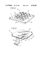
- FIG. 5 is a perspective view partially in section of the electrical switch of the invention.
- FIGS. 5A-5D are plan views of each layer of the switch of FIG. 5.
- a keypad shielded switch assembly 10 has a rectangular metal plate 21, typically of stainless steel, that lies generally in and defines a plane.
- An annular centering rim 22 projects back from the plane at the outer periphery of the plate 21 and a central and rectangular raised portion 28 projects oppositely forward from the plane, offset toward what is normally the upper edge of the plate 21 to leave space for a phone-number legend.
- This raised portion 28 in turn is formed with a regular array of twelve generally square apertures 25 of the size and shape standard in a telephone, and with rounded corners.
- a flexible silicone-rubber membrane 16 has a front face 17 lying against a back inner face 15 of the shield plate 21 and normally adhered thereto by a heavy-duty adhesive.
- the thickness of this membrane 16 plus that of any adhesive on it is about equal to the rearward projection of the rim 22 for completely enclosing the membrane when the assembly is mounted, as will be described below.
- Membrane 16 is formed with a plurality of upwardly projecting or protruding button-like portions 20. These portions 20 directly overlie the contacts 29 of the underlying switch plate 19 when the assembly is mounted.
- each portion 20 preferably has a convex portion 41 which controls the force on the contacts 29, thus reducing the possibility of excessive wear of the silicone rubber portions 20.
- the membrane 16 also has a pliable lip portion 35 formed therein about its periphery to support switch 19 snugly therein.
- each cap 24 is of prismatic cup shape and has an annular side wall or skirt 26 terminating at an outwardly turned flange or rim 18. These side walls 26 flare slightly backward, that is they are inclined at an angle of several degrees to the vertical axis of cap 24, and can fit snugly and complementarily within the respective apertures 25 with the flanges 18 lying flat against the inner face 15 of the plate 21 at the raised portion 28.
- the projections 20 fit snugly within the backs of the square caps 24 and the membrane 16 is molded such that the caps 24 are urged into their outer positions shown in FIGS. 2-3 for all but the "6" key.
- each cap 24 is axially internally slightly shorter than the height of the respective projection 20 above the membrane 16, leaving a space "s". This maintains the flange of the covers in good contact with the shield plate to provide a relatively good seal.
- the shield plate apertures are formed by being punched through from the underside of the plate, i.e. from the side which lies adjacent the membrane. This produces a shoulder or burr 43 about the outwardly facing periphery of the apertures, making it extremely difficult for a vandal to insert a pointed object into the space between the caps and the plate.
- the height of the capped projections above the shield plate is designed to be less than the total available travel of the underlying telephone push button, which is moved by pressure on the capped projection. Accordingly, even when the distal end of the capped projection is flush with the outward face of the shield plate, the telephone push-button has not quite bottomed. This assures that a vandal will not damage the switching mechanism even by impacting the capped projections with a flat, hard object--notably the telephone receiver.
- the face of each cap 24 is downwardly dished to provide a kinesthetic feel which enables the user to discern when the finger is centered on the button and to center each cap on the respective projection 20, whose front end face is complementarily concave.
- Each cap 24 bears appropriate indicia, here that of a push-type telephone pad, although of course the instant invention could equally well be used for any other type of heavy-duty keypad, such as provided on a self-service gasoline pump.
- the indicia can be stamped in and filled with a phosphorous-base ink that glows in the dark.
- FIGS. 2-3 The bolt-on embodiment of the invention is shown in FIGS. 2-3 where bolts 27 (spot-welded to the plate) are seen projecting from plate 21. These serve to secure the assembly. These bolts also go through membrane 16.
- membrane 16 has a lip 35 formed about its periphery. This lip creates a rim on the surface of the membrane opposite that which contacts plate 21.
- the surface and the walls of the lip seal and support switch assembly 19 therein.
- the elements 20 which support the push-buttons and which are the switch contacts are mounted on conical support portions 1 of the membrane. These are frustro-conical portions, and as shown in FIGS. 2 and 3, are kinesthetic break points which require an initial force to overcome the resistance of the walls of the cone and, subsequently, less force as the resistance is overcome so that both good contact is made by the interior convex surfaces 41 of elements 20 with contacts 29 on the switch assembly 19 and, the switch gives the proper "feel" to the user.
- Air passages 39 are provided between each and every conical support 1 so that air cannot be trapped in any of the cones and inhibit operation of the device.
- FIGS. 5-5D show the pressure-sensitive switch of the invention.
- the switch is seen to comprise a base layer 3 formed of solid material such as metal.
- the base layer 3 serves to support three layers of flexible material which form the switching mechanism.
- Base layer 3 has an aperture 42 formed therein which, as will be seen, acts as a support for an electrical ribbon cable 9 and an electrical connector 7.
- the switch mechanism consists of three layers of flexible material such as MYLAR.
- a base layer 23 is shown in FIG. 5A and has twelve switch contacts 29 formed thereon of electrically conductive material.
- electrical conductors 46, 48, 50 and 52 from each of the four groups of three switch contacts are laid out along the base layer 23 connecting each group to corresponding conductors on top layer 33 and then to connector 7.
- a notch 11 is cut in base layer 23 so as to interfit with aperture 42 in the support 3 again to channel and control ribbon cable 9.
- FIG. 5B shows intermediate layer 31.
- the intermediate layer is formed of MYLAR and has four series of three apertures 38 formed therein. Each of the series of apertures overlies respective ones of the switch contacts 29 in base layer 23.
- the apertures are connected to each other via spacing channels 60 in each of the groups of three to again prevent air pressure from building up in any one of the switch points or the channels so as to inhibit operation.
- a notch 5 is formed in intermediate layer 31 which interfits over aperture 42 then beneath notch 11 to guide ribbon cable 9.
- Top layer 33 has twelve switch contacts 44 formed thereon. Electrical leads are connected to these contacts so as to connect the contacts to the conductors generally shown as 13 on ribbon cable 9. These conductors are in turn electrically coupled to electrical connector 7 to connect the switch to the remaining circuitry of the telephone. Cable 9 is formed integrally with and of the same material as the top layer 33 of the pressure-actuated switch. In practice, the electrical conductors are laid out on both the top and bottom layer, 33 and 23, as a unit and these two layers are then folded over the intermediate layer 31.
- FIGS. 5A and 5C This is illustrated in FIGS. 5A and 5C.
- electrical conductors 46, 48, 50 and 52 are formed on the MYLAR layer 23. Each conductor connects a group of three electrical contacts 29 to the ribbon cable 9 and to the electrical connector 7.
- Conductor 54-55 is also shown formed on layer 23. This conductor is simply laid out on the layer for convenience as will be explained in connection with FIG. 5C.
- FIG. 5C the corresponding portions of conductors 46, 48, 50, 52, 54 and 55 are designed by numerals 46', 48', 50', 52', 54' and 55'.
- the conductor designated by numeral 54 and 54' is a single conductor joined at a fold in the MYLAR layers 23 and 33.
- numerals 46, 48, 50, 52 and 55 on layer 23 are connected to conductors 46', 48', 50', 52' and 55' on layer 33 (FIG. 5C).
- the conductors are formed on top layer 23 (FIG. 5A) connecting four groups each consisting of three contacts, while on bottom layer 33, three groups of contacts each consisting of four contacts are connected together. This configuration comports to the connections required in a telephone set. It should be clear, however, that any other configuration of contacts and connections can be used on the switch assembly of FIGS. 5A-5C.
- the conductor 54, 55 on top layer 23 connects the center group of four contacts on bottom layer 33 to the cable via conductor 54', 55'.
- the left-hand group of four contacts 33 is directly connected to the cable 9 and to the connector 7 via conductor 56, while the right-hand group is so connected via conductor 58.
- seven conductors 46', 48', 50', 52', 54', 56 and 58 appear on cable 9.
- the three layers of the pressure-sensitive switch are adhered together via suitable adhesive.
- the entire switch arrangement is then adhesively placed on the metal backing plate 3 (FIG. 5D).
- Electrical connector 7 is added as a final step.
- the electrical conductors are formed on the soft MYLAR plastic surface via the silk screening printing process.
- the material forming the electrical conductors is a silver solution.
- the arrangement of this invention therefore, presents nothing but metallic surfaces to the exterior, making it extremely rugged and virtually impossible to permanently mark or scratch.
- the numerals stamped directly in the key caps can be expected to last a long time, even in heavy service. At the same time, the assembly is wholly watertight so that it will remain dry and otherwise protected from the elements.
Abstract
Description
Claims (15)
Priority Applications (7)
| Application Number | Priority Date | Filing Date | Title |
|---|---|---|---|
| US06/801,136 US4716262A (en) | 1983-10-21 | 1985-11-22 | Vandal-resistant telephone keypad switch |
| DE19863637808 DE3637808A1 (en) | 1985-11-22 | 1986-11-06 | DESTRUCTION-SAFE TELEPHONE KEYBOARD |
| CA000522511A CA1280795C (en) | 1985-11-22 | 1986-11-07 | Vandal resistant telephone keypad switch |
| IT48671/86A IT1199297B (en) | 1985-11-22 | 1986-11-19 | VANDALISM-RESISTANT TELEPHONE KEYBOARD |
| FR8616254A FR2590754A1 (en) | 1985-11-22 | 1986-11-21 | TELEPHONE SWITCH WITH KEYBOARD WITH TOUCHES RESISTANT TO VANDALISM |
| GB8627936A GB2183401B (en) | 1985-11-22 | 1986-11-21 | Switch assemblies |
| ES8603130A ES2004495A6 (en) | 1985-11-22 | 1986-11-21 | Vandal-resistant telephone keypad switch |
Applications Claiming Priority (2)
| Application Number | Priority Date | Filing Date | Title |
|---|---|---|---|
| US06/544,391 US4555600A (en) | 1981-02-23 | 1983-10-21 | Vandal-resistant shield for telephone keypad |
| US06/801,136 US4716262A (en) | 1983-10-21 | 1985-11-22 | Vandal-resistant telephone keypad switch |
Related Parent Applications (6)
| Application Number | Title | Priority Date | Filing Date |
|---|---|---|---|
| US06/236,757 Continuation-In-Part US4438300A (en) | 1981-02-23 | 1981-02-23 | Protective cover for telephone push button array |
| US26164781A Continuation-In-Part | 1981-02-23 | 1981-05-07 | |
| US28606381A Continuation-In-Part | 1981-05-07 | 1981-07-23 | |
| US06/299,509 Continuation-In-Part US4436965A (en) | 1981-02-23 | 1981-09-04 | Sealing means for telephone cover device |
| US06/381,905 Continuation-In-Part US4501936A (en) | 1981-02-23 | 1982-05-25 | Protective cover for telephone |
| US06/544,391 Continuation-In-Part US4555600A (en) | 1981-02-23 | 1983-10-21 | Vandal-resistant shield for telephone keypad |
Publications (1)
| Publication Number | Publication Date |
|---|---|
| US4716262A true US4716262A (en) | 1987-12-29 |
Family
ID=25180291
Family Applications (1)
| Application Number | Title | Priority Date | Filing Date |
|---|---|---|---|
| US06/801,136 Expired - Fee Related US4716262A (en) | 1983-10-21 | 1985-11-22 | Vandal-resistant telephone keypad switch |
Country Status (7)
| Country | Link |
|---|---|
| US (1) | US4716262A (en) |
| CA (1) | CA1280795C (en) |
| DE (1) | DE3637808A1 (en) |
| ES (1) | ES2004495A6 (en) |
| FR (1) | FR2590754A1 (en) |
| GB (1) | GB2183401B (en) |
| IT (1) | IT1199297B (en) |
Cited By (33)
| Publication number | Priority date | Publication date | Assignee | Title |
|---|---|---|---|---|
| US4862499A (en) * | 1987-09-04 | 1989-08-29 | Phillips & Brooks, Inc. | Deformable membrane keypad assembly for public telephones |
| US4931601A (en) * | 1989-02-23 | 1990-06-05 | Eastman Kodak Company | Pressure switch having internal vent chamber |
| US4952760A (en) * | 1989-01-18 | 1990-08-28 | Spectra-Physics, Inc. | Switch cover arrangement |
| DE4212562A1 (en) * | 1992-04-15 | 1993-10-21 | Buch Elektronik Gmbh | Foil keyboard with snap-action plates under pushbuttons - has holes in front plate through which pushbuttons protrude in rest position under pressure from snap-action plates |
| US5335141A (en) * | 1989-06-23 | 1994-08-02 | Kabushiki Kaisha Toshiba | Portable electronic apparatus having a removable keyboard secured to a housing by screws protruding through the bottom wall of the housing |
| US5483418A (en) * | 1989-06-23 | 1996-01-09 | Kabushiki Kaisha Toshiba | Portable electronic apparatus having a keyboard with a shielding plate attached to a cover thereof |
| DE19522773A1 (en) * | 1995-06-27 | 1997-01-02 | Fernsprech Und Signalbau Gmbh | Environment protected keyboard e.g. for pocket calculator or phone |
| US5681122A (en) * | 1996-02-20 | 1997-10-28 | Ncr Corporation | Fluid isolation and dispersion system for tactile input devices |
| US5717429A (en) * | 1996-04-03 | 1998-02-10 | Texas Instruments Incorporated | Low profile, light weight keyboard |
| EP0685954A3 (en) * | 1994-06-03 | 1998-02-11 | Kokusai Electric Co., Ltd. | Waterproofed portable telephone |
| US5967297A (en) * | 1998-07-17 | 1999-10-19 | Methode Electronics, Inc. | Wiping elastomeric switch |
| US6103979A (en) * | 1993-08-26 | 2000-08-15 | Fujitsu Limited | Keyboard having plurality of keys therein, each key establishing different electric contacts |
| USD434425S (en) * | 1999-04-12 | 2000-11-28 | Clark Equipment Company | Display panel for power machine |
| US6202014B1 (en) | 1999-04-23 | 2001-03-13 | Clark Equipment Company | Features of main control computer for a power machine |
| EP1126481A1 (en) * | 1999-08-27 | 2001-08-22 | Mitsubishi Denki Kabushiki Kaisha | Push-button switch and switch device |
| US6343237B1 (en) | 1999-06-04 | 2002-01-29 | Clark Equipment Company | User interface functionality for power machine control system |
| FR2825187A1 (en) * | 2001-05-23 | 2002-11-29 | Sagem | Electronic payment keyboard with intrusion detection, in which movement of keyboard cover from its mounted position triggers an intrusion alarm |
| US6600120B1 (en) * | 2002-07-01 | 2003-07-29 | Koninklijke Philips Electronics N.V. | Membrane switch arrangement with chamber venting |
| US20040074756A1 (en) * | 2002-07-04 | 2004-04-22 | Canon Kabushiki Kaisha | Switch button and recording apparatus |
| US7119296B1 (en) * | 2005-06-29 | 2006-10-10 | Speed Tech Corp. | Keypad |
| US20060279095A1 (en) * | 2005-06-07 | 2006-12-14 | Mitsui Mining & Smelting Co., Ltd. | Latch release operating apparatus |
| US20070057821A1 (en) * | 2005-09-13 | 2007-03-15 | Research In Motion Limited | Keyboard for hand-held devices |
| US20070221487A1 (en) * | 2006-03-22 | 2007-09-27 | Trw Automotive Electronics & Components Gmbh & Co. Kg | Switch module |
| US20080203712A1 (en) * | 2007-02-23 | 2008-08-28 | Hawes Kevin J | Switch-based seat sensor for occupant presence detection |
| US20090135031A1 (en) * | 2007-11-26 | 2009-05-28 | Key Systems, Inc. | Armored Capacitive Keypad |
| US7665300B2 (en) | 2005-03-11 | 2010-02-23 | Massachusetts Institute Of Technology | Thin, flexible actuator array to produce complex shapes and force distributions |
| US20100275589A1 (en) * | 2007-06-08 | 2010-11-04 | Rian Scot Meyers | Electro-Hydraulic Auxiliary Mode Control |
| US20100300859A1 (en) * | 2009-05-26 | 2010-12-02 | Apple Inc. | Dome array for use with a switch |
| US20110141028A1 (en) * | 2009-12-15 | 2011-06-16 | Jimmy Bedolla | Seamless button array panels for handheld communication devices |
| US20110266128A1 (en) * | 2010-04-30 | 2011-11-03 | Silicon Laboratories, Inc. | Keypad System and Keypad with Enhanced Secutiry |
| US8283582B2 (en) | 2010-06-30 | 2012-10-09 | Research In Motion Limited | Deflection web for a keypad assembly |
| US20130140163A1 (en) * | 2011-12-05 | 2013-06-06 | Li Huang | Assembling a Keypad to a Mobile Device |
| US20140367975A1 (en) * | 2013-06-12 | 2014-12-18 | James Sanborn | Door Handle Arrangement For Vehicles |
Families Citing this family (14)
| Publication number | Priority date | Publication date | Assignee | Title |
|---|---|---|---|---|
| EP0305931A3 (en) * | 1987-08-31 | 1990-08-29 | Siemens Nixdorf Informationssysteme Aktiengesellschaft | Keyboard device |
| EP0322515A3 (en) * | 1987-12-30 | 1990-09-12 | Hewlett-Packard Company | Keyboard venting |
| GB2250380B (en) * | 1990-11-27 | 1995-01-04 | Ist Lab Ltd | Switch apparatus |
| US5199556A (en) * | 1991-10-08 | 1993-04-06 | Silitek Corporation | Structure of key switch |
| FR2688093B1 (en) * | 1992-03-02 | 1997-05-23 | Monetel | ANTI-SHOCK SURCLAVIER. |
| AT399406B (en) * | 1992-06-03 | 1995-05-26 | Frequentis Nachrichtentechnik Gmbh | TOUCH-SENSITIVE INPUT UNIT |
| GB9516621D0 (en) * | 1995-08-14 | 1995-10-18 | Wheeler Martin T | Telecommunications equipment |
| DE59605881D1 (en) * | 1996-05-28 | 2000-10-19 | Haschkamp Joachim | Push button switch for household appliances |
| DE19627213C1 (en) * | 1996-07-05 | 1997-11-20 | Hella Kg Hueck & Co | Actuation unit for electrical equipment, esp. for vehicle equipment such as air-conditioning system, entertainment and domestic equipment |
| DE10142029C1 (en) * | 2001-08-28 | 2003-01-30 | Bosch Gmbh Robert | Foil keyboard input device has flexible seal around outside of flexible foil conductor coupled to foil keyboard and fitted with electrical connector |
| ITTO20020140U1 (en) * | 2002-07-26 | 2004-01-26 | Apem Italia S R L | VANDAL-PROOF HERMETIC SEAL KEYBOARD. |
| WO2009012945A1 (en) * | 2007-07-20 | 2009-01-29 | Preh Gmbh | Flat control element for a motor vehicle |
| JP5310325B2 (en) * | 2009-07-07 | 2013-10-09 | 沖電気工業株式会社 | Keyboard structure |
| JP6975663B2 (en) * | 2018-03-01 | 2021-12-01 | アルプスアルパイン株式会社 | Switch module |
Citations (19)
| Publication number | Priority date | Publication date | Assignee | Title |
|---|---|---|---|---|
| US3699294A (en) * | 1971-05-18 | 1972-10-17 | Flex Key Corp | Keyboard, digital coding, switch for digital logic, and low power detector switches |
| GB1375333A (en) * | 1972-03-04 | 1974-11-27 | ||
| US3932722A (en) * | 1974-04-16 | 1976-01-13 | Nippo Communication Industrial Co., Ltd. | Push button body for a push-button switch providing snap-action of the switch |
| US3995126A (en) * | 1975-04-03 | 1976-11-30 | Magic Dot, Inc. | Membrane keyboard apparatus |
| US4046975A (en) * | 1975-09-22 | 1977-09-06 | Chomerics, Inc. | Keyboard switch assembly having internal gas passages preformed in spacer member |
| US4066851A (en) * | 1975-10-30 | 1978-01-03 | Chomerics, Inc. | Keyboard switch assembly having foldable printed circuit board, integral spacer and preformed depression-type alignment fold |
| US4217473A (en) * | 1978-06-26 | 1980-08-12 | W. H. Brady Co. | Connecting flexible switch |
| US4291201A (en) * | 1979-04-09 | 1981-09-22 | American Telecommunications Corporation | Push-button dial assembly for telephones |
| US4386245A (en) * | 1981-06-11 | 1983-05-31 | Hosiden Electronics Co., Ltd. | Normally-closed switching means with over-stroke compensation |
| US4440990A (en) * | 1982-05-19 | 1984-04-03 | Smk Electronics Corporation, Usa | Membrane keyboard assembly |
| US4490587A (en) * | 1983-04-07 | 1984-12-25 | Microdot Inc. | Switch assembly |
| US4499343A (en) * | 1982-03-11 | 1985-02-12 | Rogers Corporation | Monolithic flat tactile keyboard |
| US4500758A (en) * | 1983-07-05 | 1985-02-19 | Hewlett-Packard Company | Keyboard switch assembly having sensory feedback |
| US4531033A (en) * | 1983-02-01 | 1985-07-23 | Hand Widmaier Fabrik Fur Apparate Der Fernmelde-und Feinwerktechnik | Keyboard for initiating switching operations or switching signals associated with respective symbols on the surfaces of the keys |
| US4532575A (en) * | 1981-12-29 | 1985-07-30 | Canon Kabushiki Kaisha | Electronic equipment having key input function |
| US4540865A (en) * | 1983-03-01 | 1985-09-10 | Plessey Overseas Limited | Push buttons |
| US4555600A (en) * | 1981-02-23 | 1985-11-26 | Apm Corporation | Vandal-resistant shield for telephone keypad |
| US4570039A (en) * | 1983-07-30 | 1986-02-11 | Casio Computer Co., Ltd. | Keyswitch structure |
| US4580018A (en) * | 1983-09-30 | 1986-04-01 | Alps Electric Co., Ltd. | Switch device |
Family Cites Families (4)
| Publication number | Priority date | Publication date | Assignee | Title |
|---|---|---|---|---|
| US3591749A (en) * | 1969-05-12 | 1971-07-06 | Singer Co | Printed circuit keyboard |
| GB1412298A (en) * | 1972-09-05 | 1975-11-05 | Post Office | Electrical signal initiating keyboards |
| US4328399A (en) * | 1979-02-05 | 1982-05-04 | Northern Telecom Limited | Pushbutton switch assembly for telecommunications and other input |
| DE3211479A1 (en) * | 1982-03-29 | 1983-09-29 | Siemens AG, 1000 Berlin und 8000 München | Keypad for telephone sets |
-
1985
- 1985-11-22 US US06/801,136 patent/US4716262A/en not_active Expired - Fee Related
-
1986
- 1986-11-06 DE DE19863637808 patent/DE3637808A1/en not_active Withdrawn
- 1986-11-07 CA CA000522511A patent/CA1280795C/en not_active Expired - Lifetime
- 1986-11-19 IT IT48671/86A patent/IT1199297B/en active
- 1986-11-21 GB GB8627936A patent/GB2183401B/en not_active Expired
- 1986-11-21 ES ES8603130A patent/ES2004495A6/en not_active Expired
- 1986-11-21 FR FR8616254A patent/FR2590754A1/en not_active Withdrawn
Patent Citations (19)
| Publication number | Priority date | Publication date | Assignee | Title |
|---|---|---|---|---|
| US3699294A (en) * | 1971-05-18 | 1972-10-17 | Flex Key Corp | Keyboard, digital coding, switch for digital logic, and low power detector switches |
| GB1375333A (en) * | 1972-03-04 | 1974-11-27 | ||
| US3932722A (en) * | 1974-04-16 | 1976-01-13 | Nippo Communication Industrial Co., Ltd. | Push button body for a push-button switch providing snap-action of the switch |
| US3995126A (en) * | 1975-04-03 | 1976-11-30 | Magic Dot, Inc. | Membrane keyboard apparatus |
| US4046975A (en) * | 1975-09-22 | 1977-09-06 | Chomerics, Inc. | Keyboard switch assembly having internal gas passages preformed in spacer member |
| US4066851A (en) * | 1975-10-30 | 1978-01-03 | Chomerics, Inc. | Keyboard switch assembly having foldable printed circuit board, integral spacer and preformed depression-type alignment fold |
| US4217473A (en) * | 1978-06-26 | 1980-08-12 | W. H. Brady Co. | Connecting flexible switch |
| US4291201A (en) * | 1979-04-09 | 1981-09-22 | American Telecommunications Corporation | Push-button dial assembly for telephones |
| US4555600A (en) * | 1981-02-23 | 1985-11-26 | Apm Corporation | Vandal-resistant shield for telephone keypad |
| US4386245A (en) * | 1981-06-11 | 1983-05-31 | Hosiden Electronics Co., Ltd. | Normally-closed switching means with over-stroke compensation |
| US4532575A (en) * | 1981-12-29 | 1985-07-30 | Canon Kabushiki Kaisha | Electronic equipment having key input function |
| US4499343A (en) * | 1982-03-11 | 1985-02-12 | Rogers Corporation | Monolithic flat tactile keyboard |
| US4440990A (en) * | 1982-05-19 | 1984-04-03 | Smk Electronics Corporation, Usa | Membrane keyboard assembly |
| US4531033A (en) * | 1983-02-01 | 1985-07-23 | Hand Widmaier Fabrik Fur Apparate Der Fernmelde-und Feinwerktechnik | Keyboard for initiating switching operations or switching signals associated with respective symbols on the surfaces of the keys |
| US4540865A (en) * | 1983-03-01 | 1985-09-10 | Plessey Overseas Limited | Push buttons |
| US4490587A (en) * | 1983-04-07 | 1984-12-25 | Microdot Inc. | Switch assembly |
| US4500758A (en) * | 1983-07-05 | 1985-02-19 | Hewlett-Packard Company | Keyboard switch assembly having sensory feedback |
| US4570039A (en) * | 1983-07-30 | 1986-02-11 | Casio Computer Co., Ltd. | Keyswitch structure |
| US4580018A (en) * | 1983-09-30 | 1986-04-01 | Alps Electric Co., Ltd. | Switch device |
Cited By (57)
| Publication number | Priority date | Publication date | Assignee | Title |
|---|---|---|---|---|
| US4862499A (en) * | 1987-09-04 | 1989-08-29 | Phillips & Brooks, Inc. | Deformable membrane keypad assembly for public telephones |
| US4952760A (en) * | 1989-01-18 | 1990-08-28 | Spectra-Physics, Inc. | Switch cover arrangement |
| US4931601A (en) * | 1989-02-23 | 1990-06-05 | Eastman Kodak Company | Pressure switch having internal vent chamber |
| US5335141A (en) * | 1989-06-23 | 1994-08-02 | Kabushiki Kaisha Toshiba | Portable electronic apparatus having a removable keyboard secured to a housing by screws protruding through the bottom wall of the housing |
| US5483418A (en) * | 1989-06-23 | 1996-01-09 | Kabushiki Kaisha Toshiba | Portable electronic apparatus having a keyboard with a shielding plate attached to a cover thereof |
| DE4212562A1 (en) * | 1992-04-15 | 1993-10-21 | Buch Elektronik Gmbh | Foil keyboard with snap-action plates under pushbuttons - has holes in front plate through which pushbuttons protrude in rest position under pressure from snap-action plates |
| US6103979A (en) * | 1993-08-26 | 2000-08-15 | Fujitsu Limited | Keyboard having plurality of keys therein, each key establishing different electric contacts |
| EP0685954A3 (en) * | 1994-06-03 | 1998-02-11 | Kokusai Electric Co., Ltd. | Waterproofed portable telephone |
| DE19522773C2 (en) * | 1995-06-27 | 1998-01-29 | Fernsprech Und Signalbau Gmbh | keyboard |
| DE19522773A1 (en) * | 1995-06-27 | 1997-01-02 | Fernsprech Und Signalbau Gmbh | Environment protected keyboard e.g. for pocket calculator or phone |
| US5681122A (en) * | 1996-02-20 | 1997-10-28 | Ncr Corporation | Fluid isolation and dispersion system for tactile input devices |
| US5717429A (en) * | 1996-04-03 | 1998-02-10 | Texas Instruments Incorporated | Low profile, light weight keyboard |
| GB2357187A (en) * | 1998-07-17 | 2001-06-13 | Methode Electronics Inc | Wiping elastomeric switch |
| US5967297A (en) * | 1998-07-17 | 1999-10-19 | Methode Electronics, Inc. | Wiping elastomeric switch |
| WO2000004561A1 (en) * | 1998-07-17 | 2000-01-27 | Methode Electronics, Inc. | Wiping elastomeric switch |
| GB2357187B (en) * | 1998-07-17 | 2002-06-12 | Methode Electronics Inc | Wiping elastomeric switch |
| USD434425S (en) * | 1999-04-12 | 2000-11-28 | Clark Equipment Company | Display panel for power machine |
| US7142967B2 (en) | 1999-04-23 | 2006-11-28 | Clark Equipment Company | Features of main control computer for a power machine |
| US6202014B1 (en) | 1999-04-23 | 2001-03-13 | Clark Equipment Company | Features of main control computer for a power machine |
| US20030149518A1 (en) * | 1999-04-23 | 2003-08-07 | Brandt Kenneth A. | Features of main control computer for a power machine |
| US6785596B2 (en) | 1999-04-23 | 2004-08-31 | Clark Equipment Company | Features of main control computer for a power machine |
| US7496441B2 (en) | 1999-04-23 | 2009-02-24 | Clark Equipment Company | Features of main control for a power machine |
| US6343237B1 (en) | 1999-06-04 | 2002-01-29 | Clark Equipment Company | User interface functionality for power machine control system |
| EP1126481A1 (en) * | 1999-08-27 | 2001-08-22 | Mitsubishi Denki Kabushiki Kaisha | Push-button switch and switch device |
| EP1126481A4 (en) * | 1999-08-27 | 2004-12-01 | Mitsubishi Electric Corp | Push-button switch and switch device |
| FR2825187A1 (en) * | 2001-05-23 | 2002-11-29 | Sagem | Electronic payment keyboard with intrusion detection, in which movement of keyboard cover from its mounted position triggers an intrusion alarm |
| US6600120B1 (en) * | 2002-07-01 | 2003-07-29 | Koninklijke Philips Electronics N.V. | Membrane switch arrangement with chamber venting |
| US20040074756A1 (en) * | 2002-07-04 | 2004-04-22 | Canon Kabushiki Kaisha | Switch button and recording apparatus |
| US6846999B2 (en) * | 2002-07-04 | 2005-01-25 | Canon Kabushiki Kaisha | Switch button and recording apparatus |
| US7665300B2 (en) | 2005-03-11 | 2010-02-23 | Massachusetts Institute Of Technology | Thin, flexible actuator array to produce complex shapes and force distributions |
| US20060279095A1 (en) * | 2005-06-07 | 2006-12-14 | Mitsui Mining & Smelting Co., Ltd. | Latch release operating apparatus |
| US7938460B2 (en) * | 2005-06-07 | 2011-05-10 | Mitsui Mining & Smelting Co., Ltd. | Latch release operating apparatus |
| US7119296B1 (en) * | 2005-06-29 | 2006-10-10 | Speed Tech Corp. | Keypad |
| US7417565B2 (en) * | 2005-09-13 | 2008-08-26 | Research In Motion Limited | Keyboard for hand-held devices |
| US20110234500A1 (en) * | 2005-09-13 | 2011-09-29 | Research In Motion Limited | Keyboard for Hand-Held Devices |
| US20080284622A1 (en) * | 2005-09-13 | 2008-11-20 | Griffin Jason T | Keyboard for hand-held devices |
| US20070057821A1 (en) * | 2005-09-13 | 2007-03-15 | Research In Motion Limited | Keyboard for hand-held devices |
| US8330628B2 (en) | 2005-09-13 | 2012-12-11 | Research In Motion Limited | Keyboard for hand-held devices |
| US8941511B2 (en) | 2005-09-13 | 2015-01-27 | Blackberry Limited | Keyboard for hand-held devices |
| US20070221487A1 (en) * | 2006-03-22 | 2007-09-27 | Trw Automotive Electronics & Components Gmbh & Co. Kg | Switch module |
| US7638724B2 (en) * | 2006-03-22 | 2009-12-29 | Trw Automotive Electronics & Components Gmbh & Co. Kg | Switch module |
| US7523679B2 (en) * | 2007-02-23 | 2009-04-28 | Delphi Technologies, Inc. | Switch-based seat sensor for occupant presence detection |
| US20080203712A1 (en) * | 2007-02-23 | 2008-08-28 | Hawes Kevin J | Switch-based seat sensor for occupant presence detection |
| US20100275589A1 (en) * | 2007-06-08 | 2010-11-04 | Rian Scot Meyers | Electro-Hydraulic Auxiliary Mode Control |
| US8621855B2 (en) | 2007-06-08 | 2014-01-07 | Deere & Company | Electro-hydraulic auxiliary mode control |
| US20090135031A1 (en) * | 2007-11-26 | 2009-05-28 | Key Systems, Inc. | Armored Capacitive Keypad |
| US8242390B2 (en) * | 2009-05-26 | 2012-08-14 | Apple Inc. | Dome switch array |
| US20100300859A1 (en) * | 2009-05-26 | 2010-12-02 | Apple Inc. | Dome array for use with a switch |
| US20110141028A1 (en) * | 2009-12-15 | 2011-06-16 | Jimmy Bedolla | Seamless button array panels for handheld communication devices |
| US8643604B2 (en) | 2009-12-15 | 2014-02-04 | Blackberry Limited | Seamless button array panels for handheld communication devices |
| US8288672B2 (en) * | 2010-04-30 | 2012-10-16 | Silicon Laboratories Inc. | Keypad system and keypad with enhanced security |
| US20110266128A1 (en) * | 2010-04-30 | 2011-11-03 | Silicon Laboratories, Inc. | Keypad System and Keypad with Enhanced Secutiry |
| US8283582B2 (en) | 2010-06-30 | 2012-10-09 | Research In Motion Limited | Deflection web for a keypad assembly |
| US20130140163A1 (en) * | 2011-12-05 | 2013-06-06 | Li Huang | Assembling a Keypad to a Mobile Device |
| US9040850B2 (en) * | 2011-12-05 | 2015-05-26 | Blackberry Limited | Assembling a keypad to a mobile device |
| US20140367975A1 (en) * | 2013-06-12 | 2014-12-18 | James Sanborn | Door Handle Arrangement For Vehicles |
| US9353557B2 (en) * | 2013-06-12 | 2016-05-31 | Huf North America Automotive Parts Manufacturing Corp. | Door handle arrangement for vehicles |
Also Published As
| Publication number | Publication date |
|---|---|
| CA1280795C (en) | 1991-02-26 |
| IT1199297B (en) | 1988-12-30 |
| GB8627936D0 (en) | 1986-12-31 |
| FR2590754A1 (en) | 1987-05-29 |
| GB2183401A (en) | 1987-06-03 |
| IT8648671A0 (en) | 1986-11-19 |
| GB2183401B (en) | 1989-10-25 |
| ES2004495A6 (en) | 1989-01-16 |
| DE3637808A1 (en) | 1987-05-27 |
Similar Documents
| Publication | Publication Date | Title |
|---|---|---|
| US4716262A (en) | Vandal-resistant telephone keypad switch | |
| US4555600A (en) | Vandal-resistant shield for telephone keypad | |
| US4366355A (en) | Keyboard | |
| US4598181A (en) | Laminate switch assembly having improved tactile feel and improved reliability of operation | |
| US4862499A (en) | Deformable membrane keypad assembly for public telephones | |
| EP1782169B1 (en) | Thin keypad assemblies and components for electronics devices and methods | |
| US4463234A (en) | Tactile feel membrane switch assembly | |
| US4349712A (en) | Push-button switch | |
| US4127752A (en) | Tactile touch switch panel | |
| US4086451A (en) | Keyboard apparatus | |
| EP0203068B1 (en) | Improvements in switches and keyboards | |
| US4068369A (en) | Method of making pushbutton keyboard system | |
| US4421966A (en) | Keyboard elastomeric cover with buttons having changeable legends | |
| US4508942A (en) | Keyboard switch | |
| US8089014B2 (en) | Waterproof push button switch | |
| JPH04349316A (en) | Waterproof switch for electronic equipment | |
| US4734679A (en) | Pushbutton keyboard assembly | |
| JPH0216526B2 (en) | ||
| US4501936A (en) | Protective cover for telephone | |
| GB2321134A (en) | An assembly for a keypad | |
| GB1599094A (en) | Flexible sheet switches and keyboard assembly | |
| US4436965A (en) | Sealing means for telephone cover device | |
| US4438300A (en) | Protective cover for telephone push button array | |
| US4365408A (en) | Method of making membrane contact switch | |
| EP0181130A2 (en) | Push-button switch structure for telephone or the like |
Legal Events
| Date | Code | Title | Description |
|---|---|---|---|
| AS | Assignment |
Owner name: MORSE, NENA, 1 HORIZON ROAD, FORT LEE, NJ., 07024 Free format text: ASSIGNMENT OF ASSIGNORS INTEREST.;ASSIGNOR:MORSE, MILTON;REEL/FRAME:004521/0394 Effective date: 19860306 |
|
| FEPP | Fee payment procedure |
Free format text: PAYOR NUMBER ASSIGNED (ORIGINAL EVENT CODE: ASPN); ENTITY STATUS OF PATENT OWNER: SMALL ENTITY |
|
| FPAY | Fee payment |
Year of fee payment: 4 |
|
| AS | Assignment |
Owner name: MORSE, MILTON, NEW JERSEY Free format text: ASSIGNMENT OF ASSIGNORS INTEREST;ASSIGNOR:MORSE, NENA;REEL/FRAME:006556/0747 Effective date: 19930505 |
|
| REMI | Maintenance fee reminder mailed | ||
| LAPS | Lapse for failure to pay maintenance fees | ||
| FP | Lapsed due to failure to pay maintenance fee |
Effective date: 19960103 |
|
| STCH | Information on status: patent discontinuation |
Free format text: PATENT EXPIRED DUE TO NONPAYMENT OF MAINTENANCE FEES UNDER 37 CFR 1.362 |