US4716499A - Enclosed circuit board assembly - Google Patents
Enclosed circuit board assembly Download PDFInfo
- Publication number
- US4716499A US4716499A US06/889,739 US88973986A US4716499A US 4716499 A US4716499 A US 4716499A US 88973986 A US88973986 A US 88973986A US 4716499 A US4716499 A US 4716499A
- Authority
- US
- United States
- Prior art keywords
- circuit board
- cover
- computer
- assembly
- protective enclosure
- Prior art date
- Legal status (The legal status is an assumption and is not a legal conclusion. Google has not performed a legal analysis and makes no representation as to the accuracy of the status listed.)
- Expired - Fee Related
Links
Images


Classifications
-
- H—ELECTRICITY
- H05—ELECTRIC TECHNIQUES NOT OTHERWISE PROVIDED FOR
- H05K—PRINTED CIRCUITS; CASINGS OR CONSTRUCTIONAL DETAILS OF ELECTRIC APPARATUS; MANUFACTURE OF ASSEMBLAGES OF ELECTRICAL COMPONENTS
- H05K7/00—Constructional details common to different types of electric apparatus
- H05K7/14—Mounting supporting structure in casing or on frame or rack
- H05K7/1417—Mounting supporting structure in casing or on frame or rack having securing means for mounting boards, plates or wiring boards
Definitions
- the present invention generally relates to enclosures for electronic circuit boards, and particularly to a protective covering for such boards which effectively isolates the circuit board within a computer, is sufficiently ventilated to allow effective cooling of the circuit board by natural convection and/or forced convection, and provides an effective means of removing the circuit board and covering when mounted between similar assemblies.
- modems which allow a computer to send and receive data across conventional telephone lines.
- modems a contraction for modulator/demodulator
- modulator/demodulator are devices which convert digital signals from a computer or terminal into a modulated signal appropriate for transmission across conventional telephone lines.
- Most modems for personal computer use a modulation technique which is appropriate for transmission over the relatively narrow usable bandwidth of conventional phone lines.
- peripheral devices are connected to expansion slots on the mother board of the computer, as opposed to serial or parallel ports with plug connections which are external to the computer cover.
- a number of peripherals or expansion devices may be inserted into the expansion slots and the normal cover for the computer can be replaced. This arrangement allows the user to expand the capabilities of the computer without a corresponding expansion of the number of boxes and cables lying about at the computer installation site.
- modems provide an interface between the computers a telephone network.
- telephone networks typically operate on a relatively low voltage (48 volts) compared to the operating voltage supplied to the computers (120-240 volts). Therefore it is imperative that the computer supply voltage be sufficiently isolated from the telephone network, in order to avoid damage to the telephone network. Consequently, various regulation schemes have been propagated to control the design and manufacture of modems.
- the BABT regulations require the above-referenced type of housing to enclose the telephone line interface portion of the circuit in question.
- the inventors of the present invention have found it is preferable, although not necessary, to provide an enclosure for the complete circuit board. This allows the modem designer to subsequently alter the layout of components on the computer side and telco side of the telephone line interface without requiring redesign of the bureauocratically required enclosure.
- the first is the fact that most plastics exhibit a rather low coefficient of friction with human fingers, and thus it is difficult to grip the plastic housing with sufficient force to pull the circuit board/enclosure assembly out of the slot.
- use of a plastic enclosure over the board will normally (as it does in the case of the preferred embodiment of the present invention) cause the board/enclosure assembly to occupy almost the entire available inter-slot spacing. Therefore, even if the above-noted problem with friction could be overcome by the user, it is difficult to lower one's fingers on the surface of the enclosure sufficiently to get a good grip on the board to extract it in situations where adjacent expansion slots are also occupied.
- the present invention solves problems in the prior art in that it provides a compact modem circuit board enclosure which satisfies regulations such as those promulgated by the BABT in the United Kingdom, is configured to be readily inserted and removed from a standard expansion slot within a computer, and provides adequate ventilation for the circuit board.
- the device in general includes an improved protective enclosure for enclosing an electrical circuit board, comprising, a first cover including a first engagement means for engaging an edge of the circuit board, a second cover including a second engagement means for engaging an edge of the circuit board, such that when the first and second circuit board engagement means each engage the circuit board, the first and second cover means combine to enclose the circuit board.
- first and second engagement means of the device each include at least one selectively detachable locking finger.
- the present invention overcomes the above-noted problems which arise from the somewhat irrational application of the BABT enclosure regulations for devices which interface to the telephone line.
- BABT enclosure regulations for devices which interface to the telephone line.
- Such regulations make perfect sense when applied to stand-alone external devices.
- the application of the regulations to the environment of a modem for plugging into an expansion slot, which is completely enclosed within the normal case or housing of a computer during normal use has led to the design problems described in the background of the invention.
- the user has an available portion of the enclosure to grip when the modem must be removed from the computer, and yet the lateral extent of the structure is limited to the space available for a board occupying a single expansion slot.
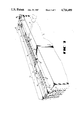
- FIG. 1 is a pictorial illustration of the enclosed circuit board assembly of the present invention.
- FIG. 2 is an exploded view of the enclosed circuit board assembly of FIG. 1.
- FIG. 3 is a partial pictorial illustration of the enclosed circuit board assembly in an installed position between two typical enclosures.
- FIG. 1 shows an assembled enclosed circuit board assembly 10 including a component side enclosure member 12, a foil side enclosure member 14, a circuit board (not shown in FIG. 1) a mounting bracket 16, and an external connecting cord 18.
- the component side enclosure member 12 encloses the side of the circuit board 20 which supports various electronic components, such as transformers, resistors, microprocessors, diodes, capacitors, etc.
- the foil side enclosure member 14 encloses the side of the circuit board 20 which supports a plurality of traces of conductive metal (not shown), which connect pins and component leads extending through the circuit board from the electronic components to electronically interconnect the circuit components. Therefore it may be seen that the component side and foil side enclosure members 12, 14, combine to substantially enclose the circuit board 20.
- the enclosed circuit board assembly 10 is typically mounted within personal computers such as those manufactured by International Business Machines. When so mounted, the enclosed circuit board assembly 10 is typically mounted as shown in FIG. 3, with the primary planar surfaces of the circuit board being vertical.
- the component side enclosure member 12 includes a cover plate 30, a lower wall 32, an upper wall 34, and end walls 36, 37.
- the cover plate 30 defines a transformer hole 38, a speaker hole 40, and pry slots 42.
- the lower wall 32 extends away at a right angle from the lower edge of the the the cover plate 30 and defines a plurality of ventilation slots 44.
- the upper wall 34 extends away from the upper edge of the cover plate 30 at a right angle and is substantially parallel to the lower wall 32.
- the upper wall 34 defines a plurality of ventilation slots (not shown), and includes two locking fingers 50 extending at right angles to the upper wall and parallel to the cover plate 30.
- the locking fingers 50 are configured to lock to the circuit board 20 and maintain a relatively rigid but detachable connection between the component side enclosure member 12 and the circuit board.
- the end walls 36, 37, of the component side enclosure member 12 extend away at right angles from the end edges of the cover plate 30, and also intersect the upper and lower walls 32, 34, to form four corner edges 54 of the component side enclosure member 12.
- the end walls 36, 37 also define a plurality of ventilation slots 44.
- reinforcement ribs 58 are provided on the circuit board side of the cover plate 30, and provide increased rigidity to the component side enclosure member 12.
- the foil side enclosure member 14 includes a lower plate 60, and an upper wall 62 extending at a right angle from the upper edge of the lower plate.
- Three locking fingers 66 extend at right angles from the upper edge of the lower plate 60, and are configured to lock to the circuit board 20 and maintain a relatively rigid but detachable connection between the foil side enclosure member 14 and the circuit board.
- Ribs 68 are provided in the lower plate 60 to provide increased rigidity to the foil side enclosure member 14.
- the circuit board 20 is substantially planar, has an upper edge 21, a bracketed edge 22, and supports the previously-discussed electronic components, denoted generally as 70, and particularly including a speaker 72, and a transformer 74.
- the circuit board 20 also includes a mounting tab 76 including a plurality of contact pads 78, which are electrically linked to the electronic components 70. As discussed later in this description, when the enclosed circuit board enclosure 10 is installed into a computer (not shown), the contact pads 78 contact cooperating contact brushes (not shown) in the computer, thus providing an operable connection between the computer and the electronic components 70 on the circuit board 20.
- the mounting bracket 16 is platelike, and includes a guide tab 80, a cord hole 82, and a slotted flange 84, which extends at a right angle from the mounting bracket.
- the connecting cord 18 extends through the cord hole 82 in the mounting bracket 16, and allows for connection of the electronic device within the circuit board enclosure to a device external to the personal computer, such as a phone line, hard disk drive, or printer.
- the connecting cord is connected to a telephone subscriber line.
- the mounting bracket 16 is fastened to the circuit board 20 by riveting or other fastening means known in the art, such that the mounting bracket extends along the bracketed edge 22 of the circuit board, and such that the primary planar surfaces of the mounting bracket are substantially perpendicular to the primary planar surfaces of the circuit board.
- the component side enclosure member 12 is placed on the circuit board 20 such that the component side of the circuit board is substantially concealed, the speaker 72 and the transformer 74 extend through the speaker hole and transformer hole 40, 38, respectively, and the locking fingers 50 engage the upper edge 21 of the circuit board.
- the foil side enclosure member 14 is placed on the circuit board such that the foil side of the circuit board 20 is concealed, and the locking fingers 66 engage the upper edge 21 if the circuit board.
- the screw holes in the component side enclosure 12, the circuit board 20, and the foil side enclosure 14 are then placed in alignment such that screws 86 may be installed.
- FIG. 3 shows the particular interlocking relationship of the locking fingers 50, 66, of the assembled enclosed circuit board assembly 10.
- the locking fingers 50 extend from the upper wall 34 of the component side enclosure member 12, and grasp the upper edge 21 of the circuit board.
- the locking fingers 66 extend from the upper wall 62 of the foil side enclosure member 14, and similarly grasp the upper edge 21 of the circuit board 20, but from the opposite side than the locking fingers 50. Therefore it may be seen that the locking fingers 50, 66, of the component side enclosure member and the foil side enclosure member 12, 14, respectively, combine to grasp the upper edge 21 of the circuit board 20, and maintain the upper edge 21 in a spaced-apart relationship between the enclosure members 12, 14.
- the enclosed circuit board assembly 10 is installed in a computer (not shown) such that the mounting tab 76 fits within a corresponding slot (not shown) in the computer and the contact pads 78 on the mounting tab are in contact with contact brushes (not shown) in the computer to allow cooperation between the computer and the circuit board as previously discussed.
- the guide tab 80 of the mounting bracket fits within a corresponding anchoring slot (not shown) defined by the frame of the computer for additional stability.
- the slotted flange 84 of the mounting bracket 16 is rigidly secured to the a frame member 87 (shown in phantom) of the computer by means of screws 88.
- FIG. 3 shows a typical sandwiched mounting configuration of the enclosed circuit board assembly 10 between two typical devices 90, 92.
- Devices 90 and 92 are shown in block form in FIG. 3 to generally represent the lateral space occupied by adjacent circuit boards in a typical environment of the preferred embodiment. It should be understood that normally devices 90 and 92 will be physically embodied by circuit boards populated with electronic components as very few computer systems will have more than one modem or other telco connected device embodying the present invention installed.
- the pry slots 42 provided in the component side enclosure provide an effective means of prying the enclosed circuit board assembly from within the other circuit board enclosures.
- a screwdriver 95 shown in phantom, or other similar prying tool may be used to engage the pry holes 42, to force the enclosed circuit board assembly 10 from its mounted position.
- the ventilation slots 44 in the enclosed circuit board assembly 10 are positioned such that air may flow through the enclosed circuit board assembly through natural convection and/or forced convection, so that there is minimal risk of overheating of the circuit board during operation.
- these slots are small enough to prevent stray wires human fingers, etc, from contacting components within the enclosure.
- the size of the ventilation slots 44 is often dictated by applicable safety codes or regulations. In the preferred embodiment of the present invention, which is particularly suited for applications in the United Kingdom, the width of the slots is 0.125", and the length is 0.325". However, it should be understood that other slot configurations or dimensions may be utilized while remaining within the spirit and scope of the present invention.
- the present invention provides an effective circuit board enclosure which effectively isolates the circuit board within a computer, is sufficiently ventilated to allow effective cooling of the circuit board by natural convection and/or forced convection, and may be easily removed when mounted between similar enclosures.
Abstract
Description
Claims (9)
Priority Applications (2)
| Application Number | Priority Date | Filing Date | Title |
|---|---|---|---|
| US06/889,739 US4716499A (en) | 1986-07-28 | 1986-07-28 | Enclosed circuit board assembly |
| GB8717436A GB2197131B (en) | 1986-07-28 | 1987-07-23 | Enclosed circuit board assembly |
Applications Claiming Priority (1)
| Application Number | Priority Date | Filing Date | Title |
|---|---|---|---|
| US06/889,739 US4716499A (en) | 1986-07-28 | 1986-07-28 | Enclosed circuit board assembly |
Publications (1)
| Publication Number | Publication Date |
|---|---|
| US4716499A true US4716499A (en) | 1987-12-29 |
Family
ID=25395705
Family Applications (1)
| Application Number | Title | Priority Date | Filing Date |
|---|---|---|---|
| US06/889,739 Expired - Fee Related US4716499A (en) | 1986-07-28 | 1986-07-28 | Enclosed circuit board assembly |
Country Status (2)
| Country | Link |
|---|---|
| US (1) | US4716499A (en) |
| GB (1) | GB2197131B (en) |
Cited By (16)
| Publication number | Priority date | Publication date | Assignee | Title |
|---|---|---|---|---|
| WO1988010061A1 (en) * | 1987-04-24 | 1988-12-15 | Western Digital Corporation | Mounting of printed circuit boards in computers |
| US4924355A (en) * | 1989-04-25 | 1990-05-08 | Dell Corporate Services Corporation | Personal computer having expansion card adapter bracket |
| US4987517A (en) * | 1989-07-03 | 1991-01-22 | Kurz Arthur A | Affixation of mounting brackets to computer circuit boards |
| US5087794A (en) * | 1990-07-19 | 1992-02-11 | Honeywell Inc. | Thermostat guard |
| US5101320A (en) * | 1991-01-22 | 1992-03-31 | Hayes Microcomputer Products, Inc. | Apparatus for rack mounting multiple circuit boards |
| WO1992019031A1 (en) * | 1991-04-19 | 1992-10-29 | Square D Company | A programmable logic controller mounting bracket |
| US5365410A (en) * | 1991-10-22 | 1994-11-15 | Nokia Mobile Phones Ltd. | Electromagnetic compatibility enclosure |
| US5396401A (en) * | 1992-07-08 | 1995-03-07 | Sextant Avionique | Modular printed circuit board holder structure, capable of engaging, in drawer-like fashion, in a rack of an electronic installation |
| US5684674A (en) * | 1996-01-16 | 1997-11-04 | Micronics Computers Inc. | Circuit board mounting brackets with convective air flow apertures |
| US6081421A (en) * | 1996-03-01 | 2000-06-27 | Compaq Computer Corporation | Portable computer having loudspeakers in enclosures formed by gaskets located between a keyboard, a printed circuit board, and a frame |
| US6137689A (en) * | 1998-05-28 | 2000-10-24 | 3Com Corporation | Protective enclosure apparatus and method |
| US20070058103A1 (en) * | 2005-09-12 | 2007-03-15 | Denso Corporation | Liquid crystal display apparatus |
| US20080205006A1 (en) * | 2003-08-08 | 2008-08-28 | Walter Fursich | Housing for Receiving Printed Circuit Boards Whose Components form at Least Parts of a Communication System |
| US20090279253A1 (en) * | 2008-05-09 | 2009-11-12 | Michael Joseph Musciano | Cooling configuration for communication boards |
| US20090279252A1 (en) * | 2008-05-09 | 2009-11-12 | Michael Joseph Musciano | Cooling air distribution scheme for communication boards |
| US20110235259A1 (en) * | 2010-03-25 | 2011-09-29 | Hon Hai Precision Industry Co., Ltd. | Expansion card assembly and heat shielding cover for expansion card thereof |
Families Citing this family (1)
| Publication number | Priority date | Publication date | Assignee | Title |
|---|---|---|---|---|
| GB2313959B (en) * | 1996-06-04 | 2001-10-10 | Pyronix Ltd | Electronic circuit device and enclosure |
Citations (6)
| Publication number | Priority date | Publication date | Assignee | Title |
|---|---|---|---|---|
| US3668476A (en) * | 1970-09-11 | 1972-06-06 | Seeburg Corp | Self-locking enclosure for electronic circuitry and method of assembling the same |
| US3693410A (en) * | 1970-02-02 | 1972-09-26 | Bendix Corp | Disposable air sampling filter cassette |
| US4149027A (en) * | 1977-05-27 | 1979-04-10 | Atari, Inc. | TV game cartridge and method |
| US4295179A (en) * | 1979-12-18 | 1981-10-13 | Northern Telecom Limited | Electric test equipment housing |
| US4409641A (en) * | 1980-06-02 | 1983-10-11 | Robert Bosch Gmbh | Environmentally protected electronic network structure and housing combination |
| US4447856A (en) * | 1980-10-24 | 1984-05-08 | Fujitsu Limited | Shelf unit for electronic communication devices |
Family Cites Families (5)
| Publication number | Priority date | Publication date | Assignee | Title |
|---|---|---|---|---|
| GB1159682A (en) * | 1965-11-15 | 1969-07-30 | Newmatic Electrical Ltd | Combined Radio Chassis and Cabinet Structure. |
| GB2029645B (en) * | 1978-08-07 | 1982-07-14 | Mitsumi Electric Co Ltd | High-frequency circuit device |
| DE3019645A1 (en) * | 1980-05-22 | 1981-12-03 | Siemens AG, 1000 Berlin und 8000 München | INSULATED INSERT WITH HIGH STRENGTH RESISTANCE |
| JPS60118269U (en) * | 1984-01-20 | 1985-08-09 | アルプス電気株式会社 | case for electronic equipment |
| EP0181286A1 (en) * | 1984-10-29 | 1986-05-14 | Ascom Autophon Ag | Shielded device for protecting telecommunication lines against disturbances |
-
1986
- 1986-07-28 US US06/889,739 patent/US4716499A/en not_active Expired - Fee Related
-
1987
- 1987-07-23 GB GB8717436A patent/GB2197131B/en not_active Expired - Fee Related
Patent Citations (6)
| Publication number | Priority date | Publication date | Assignee | Title |
|---|---|---|---|---|
| US3693410A (en) * | 1970-02-02 | 1972-09-26 | Bendix Corp | Disposable air sampling filter cassette |
| US3668476A (en) * | 1970-09-11 | 1972-06-06 | Seeburg Corp | Self-locking enclosure for electronic circuitry and method of assembling the same |
| US4149027A (en) * | 1977-05-27 | 1979-04-10 | Atari, Inc. | TV game cartridge and method |
| US4295179A (en) * | 1979-12-18 | 1981-10-13 | Northern Telecom Limited | Electric test equipment housing |
| US4409641A (en) * | 1980-06-02 | 1983-10-11 | Robert Bosch Gmbh | Environmentally protected electronic network structure and housing combination |
| US4447856A (en) * | 1980-10-24 | 1984-05-08 | Fujitsu Limited | Shelf unit for electronic communication devices |
Non-Patent Citations (1)
| Title |
|---|
| IBM Tech. Discl. Bull., vol. 21, No. 11, Apr. 1979, pp. 4487, Power Feeder Housing, Arnold. * |
Cited By (21)
| Publication number | Priority date | Publication date | Assignee | Title |
|---|---|---|---|---|
| WO1988010061A1 (en) * | 1987-04-24 | 1988-12-15 | Western Digital Corporation | Mounting of printed circuit boards in computers |
| US4924355A (en) * | 1989-04-25 | 1990-05-08 | Dell Corporate Services Corporation | Personal computer having expansion card adapter bracket |
| US4987517A (en) * | 1989-07-03 | 1991-01-22 | Kurz Arthur A | Affixation of mounting brackets to computer circuit boards |
| US5087794A (en) * | 1990-07-19 | 1992-02-11 | Honeywell Inc. | Thermostat guard |
| US5101320A (en) * | 1991-01-22 | 1992-03-31 | Hayes Microcomputer Products, Inc. | Apparatus for rack mounting multiple circuit boards |
| WO1992019031A1 (en) * | 1991-04-19 | 1992-10-29 | Square D Company | A programmable logic controller mounting bracket |
| US5365410A (en) * | 1991-10-22 | 1994-11-15 | Nokia Mobile Phones Ltd. | Electromagnetic compatibility enclosure |
| US5396401A (en) * | 1992-07-08 | 1995-03-07 | Sextant Avionique | Modular printed circuit board holder structure, capable of engaging, in drawer-like fashion, in a rack of an electronic installation |
| US5684674A (en) * | 1996-01-16 | 1997-11-04 | Micronics Computers Inc. | Circuit board mounting brackets with convective air flow apertures |
| US6081421A (en) * | 1996-03-01 | 2000-06-27 | Compaq Computer Corporation | Portable computer having loudspeakers in enclosures formed by gaskets located between a keyboard, a printed circuit board, and a frame |
| US6137689A (en) * | 1998-05-28 | 2000-10-24 | 3Com Corporation | Protective enclosure apparatus and method |
| US20080205006A1 (en) * | 2003-08-08 | 2008-08-28 | Walter Fursich | Housing for Receiving Printed Circuit Boards Whose Components form at Least Parts of a Communication System |
| US7903429B2 (en) * | 2003-08-08 | 2011-03-08 | Siemens Aktiengesellschaft | Housing for receiving printed circuit boards whose components form at least parts of a communication system |
| US20070058103A1 (en) * | 2005-09-12 | 2007-03-15 | Denso Corporation | Liquid crystal display apparatus |
| US7965340B2 (en) * | 2005-09-12 | 2011-06-21 | Denso Corporation | Liquid crystal display apparatus |
| US20090279253A1 (en) * | 2008-05-09 | 2009-11-12 | Michael Joseph Musciano | Cooling configuration for communication boards |
| US20090279252A1 (en) * | 2008-05-09 | 2009-11-12 | Michael Joseph Musciano | Cooling air distribution scheme for communication boards |
| US7679920B2 (en) | 2008-05-09 | 2010-03-16 | Solarflare Communications, Inc. | Cooling air distribution scheme for communication boards |
| US20110110038A1 (en) * | 2008-05-09 | 2011-05-12 | Michael Joseph Musciano | Cooling configuration for communication boards |
| US8345418B2 (en) | 2008-05-09 | 2013-01-01 | Marvell International Ltd. | Cooling configuration for communication boards |
| US20110235259A1 (en) * | 2010-03-25 | 2011-09-29 | Hon Hai Precision Industry Co., Ltd. | Expansion card assembly and heat shielding cover for expansion card thereof |
Also Published As
| Publication number | Publication date |
|---|---|
| GB8717436D0 (en) | 1987-08-26 |
| GB2197131A (en) | 1988-05-11 |
| GB2197131B (en) | 1990-08-22 |
Similar Documents
| Publication | Publication Date | Title |
|---|---|---|
| US4716499A (en) | Enclosed circuit board assembly | |
| US5207586A (en) | Integral connector system for credit card size I/O card external connector | |
| US6411522B1 (en) | Integrated computer module with EMI shielding plate | |
| US6088222A (en) | Computer peripheral chassis frame structure having a split lance for location, electrical grounding, and load bearing of chassis carriers | |
| KR100261382B1 (en) | Multigigabit adaptable transceiver module | |
| US6229709B1 (en) | Printed circuit board card guide | |
| JPH07109948B2 (en) | Circuit card accommodation device | |
| US5863211A (en) | Inter-book-package mechanical and electrical connection system | |
| US7025635B2 (en) | Structure of connector for reducing electro-magnetic wave interference | |
| US5040993A (en) | Interchangeable adapter module for electronic devices | |
| WO1988000790A1 (en) | Apparatus for expanding the input/output capabilities of a personal computer | |
| US5214567A (en) | Modular peripheral platform having two disk drives and one electrical connector | |
| US5808869A (en) | Method and apparatus for transferring heat from a PCMCIA card | |
| JPH05226019A (en) | Electric connector | |
| US5174762A (en) | Circuit board adapter for computer system | |
| US8285906B2 (en) | Alternate use of computer storage device bays | |
| JPH09180836A (en) | Communication outlet | |
| JP3779326B2 (en) | Transient voltage surge protection assembly for communication lines | |
| US6896553B2 (en) | Electrical connector with an integrated modem | |
| EP0754401B1 (en) | A cable connection and shielding device | |
| US5605463A (en) | Performance of add in printed circuit cards for computer systems | |
| HUT68301A (en) | Data communications outlet kit | |
| US5779499A (en) | Computer interface multiple input connecting device | |
| EP0079805A2 (en) | Communication equipment housing | |
| US6250932B1 (en) | Insulating divider and connector for hot plug adapter card slots |
Legal Events
| Date | Code | Title | Description |
|---|---|---|---|
| AS | Assignment |
Owner name: HAYES MICROCOMPUTER PRODUCTS, INC., 705 WESTECH DR Free format text: ASSIGNMENT OF ASSIGNORS INTEREST.;ASSIGNOR:BHARGAVA, VIKRAM;REEL/FRAME:004584/0608 Effective date: 19860722 Owner name: HAYES MICROCOMPUTER PRODUCTS, INC.,GEORGIA Free format text: ASSIGNMENT OF ASSIGNORS INTEREST;ASSIGNOR:BHARGAVA, VIKRAM;REEL/FRAME:004584/0608 Effective date: 19860722 |
|
| FEPP | Fee payment procedure |
Free format text: PAYOR NUMBER ASSIGNED (ORIGINAL EVENT CODE: ASPN); ENTITY STATUS OF PATENT OWNER: LARGE ENTITY |
|
| FPAY | Fee payment |
Year of fee payment: 4 |
|
| AS | Assignment |
Owner name: GENERAL ELECTRIC CAPITAL CORPORATION, GEORGIA Free format text: SECURITY AGREEMENT;ASSIGNOR:HAYES MICROCOMPUTER PRODUCTS, INC.;REEL/FRAME:007732/0954 Effective date: 19950714 |
|
| REMI | Maintenance fee reminder mailed | ||
| LAPS | Lapse for failure to pay maintenance fees | ||
| FP | Lapsed due to failure to pay maintenance fee |
Effective date: 19960103 |
|
| AS | Assignment |
Owner name: GENERAL ELECTRIC CAPITAL CORPORATION, GEORGIA Free format text: RELEASE OF SECURITY INTEREST;ASSIGNOR:HAYES MICROCOMPUTER PRODUCTS, INC.;REEL/FRAME:007991/0175 Effective date: 19960326 |
|
| STCH | Information on status: patent discontinuation |
Free format text: PATENT EXPIRED DUE TO NONPAYMENT OF MAINTENANCE FEES UNDER 37 CFR 1.362 |